EP1540326B1 - Controlling the cleanliness of surfaces - Google Patents
Controlling the cleanliness of surfaces Download PDFInfo
- Publication number
- EP1540326B1 EP1540326B1 EP03722982A EP03722982A EP1540326B1 EP 1540326 B1 EP1540326 B1 EP 1540326B1 EP 03722982 A EP03722982 A EP 03722982A EP 03722982 A EP03722982 A EP 03722982A EP 1540326 B1 EP1540326 B1 EP 1540326B1
- Authority
- EP
- European Patent Office
- Prior art keywords
- coating
- cleanliness
- value
- degree
- values
- Prior art date
- Legal status (The legal status is an assumption and is not a legal conclusion. Google has not performed a legal analysis and makes no representation as to the accuracy of the status listed.)
- Expired - Lifetime
Links
- 230000003749 cleanliness Effects 0.000 title claims description 30
- 238000000576 coating method Methods 0.000 claims abstract description 38
- 239000011248 coating agent Substances 0.000 claims abstract description 37
- 238000000034 method Methods 0.000 claims abstract description 35
- 239000000463 material Substances 0.000 claims abstract description 5
- 239000004020 conductor Substances 0.000 claims abstract description 4
- 238000000151 deposition Methods 0.000 claims description 17
- 238000004140 cleaning Methods 0.000 claims description 4
- 230000003746 surface roughness Effects 0.000 abstract 2
- 230000008021 deposition Effects 0.000 description 13
- 238000005259 measurement Methods 0.000 description 10
- 238000005238 degreasing Methods 0.000 description 6
- 238000011282 treatment Methods 0.000 description 6
- 239000000758 substrate Substances 0.000 description 5
- 238000011109 contamination Methods 0.000 description 4
- 230000001066 destructive effect Effects 0.000 description 4
- 238000004519 manufacturing process Methods 0.000 description 4
- 238000002604 ultrasonography Methods 0.000 description 4
- 238000010276 construction Methods 0.000 description 3
- 239000010410 layer Substances 0.000 description 3
- RYGMFSIKBFXOCR-UHFFFAOYSA-N Copper Chemical compound [Cu] RYGMFSIKBFXOCR-UHFFFAOYSA-N 0.000 description 2
- PXHVJJICTQNCMI-UHFFFAOYSA-N Nickel Chemical compound [Ni] PXHVJJICTQNCMI-UHFFFAOYSA-N 0.000 description 2
- 229910000831 Steel Inorganic materials 0.000 description 2
- 230000003247 decreasing effect Effects 0.000 description 2
- 239000003599 detergent Substances 0.000 description 2
- 229910003460 diamond Inorganic materials 0.000 description 2
- 239000010432 diamond Substances 0.000 description 2
- 239000003292 glue Substances 0.000 description 2
- 239000012212 insulator Substances 0.000 description 2
- 239000002184 metal Substances 0.000 description 2
- 229910052751 metal Inorganic materials 0.000 description 2
- 239000011241 protective layer Substances 0.000 description 2
- 239000000523 sample Substances 0.000 description 2
- 239000010959 steel Substances 0.000 description 2
- XLYOFNOQVPJJNP-UHFFFAOYSA-N water Substances O XLYOFNOQVPJJNP-UHFFFAOYSA-N 0.000 description 2
- XSTXAVWGXDQKEL-UHFFFAOYSA-N Trichloroethylene Chemical group ClC=C(Cl)Cl XSTXAVWGXDQKEL-UHFFFAOYSA-N 0.000 description 1
- 239000002390 adhesive tape Substances 0.000 description 1
- 238000002144 chemical decomposition reaction Methods 0.000 description 1
- 229910052802 copper Inorganic materials 0.000 description 1
- 239000010949 copper Substances 0.000 description 1
- 238000005336 cracking Methods 0.000 description 1
- 230000007423 decrease Effects 0.000 description 1
- 230000001419 dependent effect Effects 0.000 description 1
- 230000000694 effects Effects 0.000 description 1
- 238000010291 electrical method Methods 0.000 description 1
- 239000003344 environmental pollutant Substances 0.000 description 1
- 239000003925 fat Substances 0.000 description 1
- PCHJSUWPFVWCPO-UHFFFAOYSA-N gold Chemical compound [Au] PCHJSUWPFVWCPO-UHFFFAOYSA-N 0.000 description 1
- 239000010931 gold Substances 0.000 description 1
- 229910052737 gold Inorganic materials 0.000 description 1
- 238000002513 implantation Methods 0.000 description 1
- 238000000691 measurement method Methods 0.000 description 1
- 238000012986 modification Methods 0.000 description 1
- 230000004048 modification Effects 0.000 description 1
- 229910052759 nickel Inorganic materials 0.000 description 1
- 239000006223 plastic coating Substances 0.000 description 1
- 231100000719 pollutant Toxicity 0.000 description 1
- 238000003825 pressing Methods 0.000 description 1
- 238000004544 sputter deposition Methods 0.000 description 1
- 238000001771 vacuum deposition Methods 0.000 description 1
Images

Classifications
-
- G—PHYSICS
- G01—MEASURING; TESTING
- G01N—INVESTIGATING OR ANALYSING MATERIALS BY DETERMINING THEIR CHEMICAL OR PHYSICAL PROPERTIES
- G01N27/00—Investigating or analysing materials by the use of electric, electrochemical, or magnetic means
- G01N27/60—Investigating or analysing materials by the use of electric, electrochemical, or magnetic means by investigating electrostatic variables, e.g. electrographic flaw testing
Definitions
- the surfaces of the electrically conductive parts, and in particular metal, are very often contaminated by pollutants such as oxides or fats even after being cleaned.
- a coating for example a protective layer or glue
- the present invention aims to overcome the aforementioned drawbacks.
- a method of constructing a correspondence table for the cleanliness control of first surfaces made in the same electrically conductive material and having substantially identical mechanical surface states in which process, for each surface of a plurality of second surfaces made of the same material as the first surfaces and having mechanical surface conditions substantially identical to those of the first surfaces and degrees of cleanliness different from each other, a first electrical value representative of the degree of cleanliness of the surface, depositing a coating on the surface, which coating is of the same type for all second surfaces, is measured a second value representative of the degree of adhesion of the coating on the surface and the first and second values are included in the correspondence table.
- mechanical surface condition is meant the more or less polished or rough character of the surface.
- the degree of adhesion of a coating to a surface of a substrate is proportional to the degree of cleanliness of said surface.
- the present invention thus reliably verifies, in a manufacturing process and before proceeding with the deposition of the coating, whether the corresponding surface of the substrate is clean enough to guarantee the success of the subsequent coating deposition operation. If it is determined that the part is not sufficiently clean, the electrical value obtained being less than a determined threshold corresponding to a desired minimum adhesion threshold, this part can be discarded or be subjected to additional cleaning.
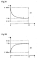
- the figure 3A shows the curve of the surface potential as a function of time, V (t), which is obtained in the case of a part 2 whose surface 20 is contaminated.
- V (t) the curve of the surface potential as a function of time
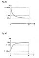
- the figure 3B shows the curve of the surface potential as a function of time, V (t), which is obtained in the case of a part 2 whose surface 20 is very clean. This curve is increasing and starts from a potential of beginning of measurement V start negative, raised immediately after the deposition of charges, to tend towards the initial potential Vinit.
- FIGS. Figures 3A and 3B show two cases, respectively for a contaminated room and a very clean room, in which the potential decreases / grows beyond the initial potential Vinit. These cases occur when the amount of deposited charges is too great and has resulted in a chemical degradation of the contamination layer present on the surface 20. To obtain exploitable curves, of the type illustrated in FIGS. Figures 3A and 3B this amount of charge should be reduced, for example by decreasing the exposure time of the surface 20.
- This table can be used in the production of parts identical to those used in the construction of the table and intended to receive a coating of the same type as that used for the construction of the table. It will allow its user to know the degree of adhesion of the coating on a given piece, or at least to have a relatively accurate idea, before the deposition of this coating, by a non-destructive electrical measurement similar to step E1 described above, and therefore without resorting to a destructive method of direct measurement of adhesion.
Abstract
Description
La présente invention concerne le contrôle de propreté de surfaces électriquement conductrices et destinées à recevoir un revêtement.The present invention relates to the control of cleanliness of electrically conductive surfaces and intended to receive a coating.
Les surfaces des pièces électriquement conductrices, et notamment métalliques, sont très souvent contaminées par des polluants tels que des oxydes ou des corps gras et ce même après avoir été nettoyées.The surfaces of the electrically conductive parts, and in particular metal, are very often contaminated by pollutants such as oxides or fats even after being cleaned.
Lorsque l'on souhaite déposer un revêtement, par exemple une couche de protection ou de colle, sur une surface d'un substrat, il est important de pouvoir contrôler au préalable l'état de propreté ou niveau de contamination de ladite surface. De cet état de propreté dépendra en effet la qualité de la liaison entre le substrat et le revêtement.When it is desired to deposit a coating, for example a protective layer or glue, on a surface of a substrate, it is important to be able to check in advance the state of cleanliness or level of contamination of said surface. This state of cleanliness will indeed depend on the quality of the bond between the substrate and the coating.
Plusieurs techniques existent à ce jour pour contrôler l'état de propreté d'une surface électriquement conductrice. La plus conventionnelle d'entre elles est la technique dite de « mouillabilité », consistant à vérifier si la surface, lorsqu'elle est mise en présence d'eau, laisse se former un film d'eau continu. Cette technique essentiellement qualitative ne permet pas de quantifier le degré de propreté de la surface. Une autre technique est décrite dans le brevet américain
D'autres méthodes ont été proposées qui sont capables de délivrer des valeurs électriques dépendant du degré de propreté. La plus fiable de ces méthodes semble être celle décrite dans la demande de brevet français
La présente invention vise à remédier aux inconvénients précités.The present invention aims to overcome the aforementioned drawbacks.
A cette fin, il est prévu selon l'invention un procédé de construction d'une table de correspondance pour le contrôle de propreté de premières surfaces faites dans une même matière électriquement conductrice et ayant des états de surface mécaniques sensiblement identiques, procédé dans lequel, pour chaque surface d'une pluralité de secondes surfaces faites dans la même matière que les premières surfaces et ayant des états de surface mécaniques sensiblement identiques à ceux des premières surfaces et des degrés de propreté différents les uns des autres, l'on détermine une première valeur électrique représentative du degré de propreté de la surface, l'on dépose un revêtement sur la surface, revêtement qui est du même type pour toutes les secondes surfaces, l'on mesure une seconde valeur représentative du degré d'adhérence du revêtement sur la surface et l'on inclut dans la table de correspondance les première et seconde valeurs. Par « état de surface mécanique » on entend le caractère plus ou moins poli ou rugueux de la surface.To this end, there is provided according to the invention a method of constructing a correspondence table for the cleanliness control of first surfaces made in the same electrically conductive material and having substantially identical mechanical surface states, in which process, for each surface of a plurality of second surfaces made of the same material as the first surfaces and having mechanical surface conditions substantially identical to those of the first surfaces and degrees of cleanliness different from each other, a first electrical value representative of the degree of cleanliness of the surface, depositing a coating on the surface, which coating is of the same type for all second surfaces, is measured a second value representative of the degree of adhesion of the coating on the surface and the first and second values are included in the correspondence table. By "mechanical surface condition" is meant the more or less polished or rough character of the surface.
La présente invention prévoit également l'utilisation d'une table de correspondance selon la revendication 7.The present invention also provides the use of a look-up table according to claim 7.
La présente invention repose sur la constatation que, si aucun procédé de contrôle de propreté existant à ce jour ne peut réellement quantifier l'état de propreté d'une surface, les procédés de mesure d'adhérence sont eux capables de fournir des valeurs caractéristiques du degré d'adhérence d'un revêtement sur un substrat et immédiatement interprétables par un homme du métier.The present invention is based on the observation that, if no cleanliness control method existing to date can really quantify the state of cleanliness of a surface, the adhesion measurement methods are capable of providing characteristic values of the surface. degree of adhesion of a coating to a substrate and immediately interpretable by a person skilled in the art.
Or le degré d'adhérence d'un revêtement sur une surface d'un substrat est proportionnel au degré de propreté de ladite surface. Par la table de correspondance selon l'invention, il est donc possible, après une mesure électrique de l'état de propreté d'une surface électriquement conductrice destinée à recevoir un revêtement donné, de connaître par avance le degré d'adhérence, valeur directement interprétable, qui sera obtenu après le dépôt du revêtement sur la surface.However, the degree of adhesion of a coating to a surface of a substrate is proportional to the degree of cleanliness of said surface. By the correspondence table according to the invention, it is therefore possible, after an electrical measurement of the state of cleanliness of an electrically conductive surface intended to receive a given coating, to know in advance the degree of adhesion, value directly. interpretable, which will be obtained after the deposition of the coating on the surface.
Il est important de noter que les procédés actuels de mesure d'adhérence sont relativement compliqués à mettre en oeuvre et, surtout, sont destructifs, c'est-à-dire qu'ils endommagent de manière irréversible les pièces qu'ils analysent. L'emploi de tels procédés dans des chaînes de production apparaît donc exclu. En revanche, les procédés électriques de contrôle de propreté sont généralement simples d'utilisation et n'ont aucun caractère destructif. La présente invention permet donc de vérifier de manière fiable, dans un processus de fabrication et avant de procéder au dépôt du revêtement, si la surface correspondante du substrat est suffisamment propre pour garantir le succès de l'opération ultérieure de dépôt du revêtement. S'il est déterminé que la pièce n'est pas suffisamment propre, la valeur électrique obtenue étant inférieure à un seuil déterminé correspondant à un seuil minimal d'adhérence souhaité, cette pièce pourra être écartée ou être soumise à un nettoyage supplémentaire.It is important to note that the current methods of adhesion measurement are relatively complicated to implement and, above all, are destructive, that is to say they irreversibly damage the parts they analyze. The use of such processes in production lines therefore appears to be excluded. On the other hand, electrical methods of cleanliness control are generally easy to use and have no destructive character. The present invention thus reliably verifies, in a manufacturing process and before proceeding with the deposition of the coating, whether the corresponding surface of the substrate is clean enough to guarantee the success of the subsequent coating deposition operation. If it is determined that the part is not sufficiently clean, the electrical value obtained being less than a determined threshold corresponding to a desired minimum adhesion threshold, this part can be discarded or be subjected to additional cleaning.
D'autres caractéristiques et avantages de la présente invention apparaîtront à la lecture de la description détaillée suivante faite en référence aux dessins annexés dans lesquels :
- la
figure 1 montre une succession d'étapes mises en oeuvre par le procédé selon l'invention ; - les
figures 2A et 2B montrent schématiquement un dispositif de contrôle de propreté de surface utilisé dans l'invention ; et - les
figures 3A à 3D représentent des courbes de potentiel en fonction du temps obtenues avec le dispositif desfigures 2A et 2B .
- the
figure 1 shows a succession of steps implemented by the method according to the invention; - the
Figures 2A and 2B schematically show a surface cleanliness control device used in the invention; and - the
Figures 3A to 3D represent potential curves as a function of time obtained with the device of theFigures 2A and 2B .
En référence à la
- une première étape E1 au cours de laquelle une valeur électrique caractéristique de l'état de propreté d'une surface de la pièce est déterminée,
- une seconde étape E2 au cours de laquelle un revêtement est déposé sur ladite surface,
- une troisième étape E3 au cours de laquelle le degré d'adhérence du revêtement sur ladite surface est mesuré, et
- une quatrième étape E4 au cours de laquelle les valeurs de propreté et d'adhérence obtenues aux étapes E1 et E3 sont incluses dans la table de correspondance.
- a first step E1 during which an electrical value characteristic of the state of cleanliness of a surface of the part is determined,
- a second step E2 during which a coating is deposited on said surface,
- a third step E3 during which the degree of adhesion of the coating to said surface is measured, and
- a fourth step E4 during which the cleanliness and adhesion values obtained in steps E1 and E3 are included in the correspondence table.
L'étape E1 est mise en oeuvre, de préférence, à l'aide d'un dispositif de contrôle de propreté de surface du type de celui décrit dans le document
Ce dispositif comporte, comme illustré à la
Après cette opération de dépôt de charges positives, la sonde d'un voltmètre électrostatique 3 est placée sur la zone de la surface 20 précédemment en regard de la grille 13, de telle manière que l'axe de la sonde soit perpendiculaire à la surface 20 en passant par le centre de la zone précitée (
La
La
Les
A partir de ces courbes de potentiel, l'unité de traitement 4 calcule une valeur électrique représentative de la variation du potentiel en fonction du temps. Cette valeur électrique est par exemple une valeur dérivée dV/dt prise à un ou plusieurs instants prédéterminés après le dépôt de charges, comme le propose le document
Il va de soi que les conditions de mise en oeuvre de l'étape E1 décrite ci-dessus, en particulier la quantité de charges déposées et le temps d'acquisition t0, sont identiques pour toutes les pièces de l'ensemble.It goes without saying that the conditions of implementation of step E1 described above, in particular the quantity of charges deposited and the acquisition time t0, are identical for all the parts of the assembly.
L'étape E2 est une étape classique de dépôt sous vide. Le type de revêtement déposé est le même pour toutes les pièces de l'ensemble. On entend par là que la matière constituant le revêtement est la même pour toutes ces pièces, l'épaisseur du revêtement pouvant en revanche varier. Le revêtement déposé à l'étape. E2 est par exemple une couche de protection ou de colle.Step E2 is a conventional vacuum deposition step. The type of coating deposited is the same for all parts of the set. By this is meant that the material constituting the coating is the same for all these parts, the thickness of the coating may however vary. The coating deposited in step. E2 is for example a protective layer or glue.
L'étape E3 est mise en oeuvre, de préférence, à l'aide d'un dispositif commercialisé par la société suisse CSEM Instruments sous le nom de « NANO-SCRATCH TESTER » (marque déposée). Ce dispositif mesure l'adhérence d'un revêtement en effectuant une rayure sur celui-ci au moyen d'une pointe diamantée sur laquelle est appliquée une force normale croissante. La valeur d'adhérence du revêtement correspond à l'intensité de la force appliquée à la pointe diamantée à l'instant de rupture de ce revêtement, dans le cas de revêtements métalliques, ou à l'instant de fissure du revêtement, dans le cas de revêtements plastiques. Cette valeur d'adhérence est généralement exprimée en mN.Step E3 is preferably implemented using a device marketed by the Swiss company CSEM Instruments under the name "NANO-SCRATCH TESTER" (registered trademark). This device measures the adhesion of a coating by making a scratch on it by means of a diamond point on which is applied an increasing normal force. The adhesion value of the coating corresponds to the intensity of the force applied to the diamond point at the time of rupture of this coating, in the case of metal coatings, or at the time of cracking of the coating, in the case of plastic coatings. This adhesion value is generally expressed in mN.
L'étape E4 consiste à inclure dans une base de données la valeur électrique dV/dt ou ΔV représentative du degré de propreté de la surface 20 et la valeur correspondante d'adhérence du revêtement sur cette surface.Step E4 consists in including in a database the electrical value dV / dt or ΔV representative of the degree of cleanliness of the
Ainsi, après la mise en oeuvre des étapes E1 à E4 pour chaque pièce de l'ensemble, une table de correspondance est construite comprenant des valeurs électriques représentatives de différents degrés de propreté de surfaces identiques électriquement conductrices et des valeurs correspondantes d'adhérence associées à un type de revêtement donné susceptible d'être déposé sur ces surfaces.Thus, after the implementation of steps E1 to E4 for each part of the assembly, a correspondence table is constructed comprising electrical values representative of different degrees of cleanliness of identical electrically conductive surfaces and corresponding values of adhesion associated with a type of coating that can be deposited on these surfaces.
Cette table pourra être utilisée lors de la production de pièces identiques à celles ayant servi à la construction de la table et destinées à recevoir un revêtement du même type que celui ayant servi à la construction de la table. Elle permettra en effet à son utilisateur de connaître le degré d'adhérence du revêtement sur une pièce donnée, ou à tout le moins d'en avoir une idée relativement précise, avant le dépôt de ce revêtement, par une mesure électrique non destructive semblable à l'étape E1 décrite ci-dessus, et donc sans recourir à un procédé destructif de mesure directe d'adhérence.This table can be used in the production of parts identical to those used in the construction of the table and intended to receive a coating of the same type as that used for the construction of the table. It will allow its user to know the degree of adhesion of the coating on a given piece, or at least to have a relatively accurate idea, before the deposition of this coating, by a non-destructive electrical measurement similar to step E1 described above, and therefore without resorting to a destructive method of direct measurement of adhesion.
On va maintenant décrire, à titre indicatif, quelques exemples numériques de mise en oeuvre du procédé selon l'invention.We will now describe, as an indication, some numerical examples of implementation of the method according to the invention.
Quatre pièces en cuivre identiques A, B, C, D sont préparées.Four identical copper pieces A, B, C, D are prepared.
La pièce A n'est pas nettoyée.Room A is not cleaned.
La pièce B subit un traitement de dégraissage au trichloéthylène sous ultra-sons.Room B undergoes a trichloethylene degreasing treatment under ultrasound.
La pièce C subit un traitement de dégraissage sous ultra-sons, utilisant une lessive commercialisée par la demanderesse sous la référence « NGL 17.40P ».Part C undergoes a degreasing treatment under ultrasound, using a laundry marketed by the applicant under the reference "NGL 17.40P".
La pièce D est avivée.Room D is brightened.
Ensuite, pour chacune de ces pièces, l'on dépose sur une zone de 1 cm2 de la surface de la pièce des charges électriques positives de 1 µC en 5 secondes. Immédiatement après ce dépôt, l'on relève le potentiel au centre de la zone précitée et l'on détermine la différence ΔV entre le potentiel Vfin pris 30 secondes après le début de la mesure et le potentiel Vdébut de début de mesure. Puis l'on dépose une couche de nickel et l'on mesure le degré d'adhérence de ce revêtement à l'aide du « NANO-SCRATCH TESTER ».Then, for each of these parts, is deposited on a 1 cm 2 area of the surface of the room positive electrical charges of 1 μC in 5 seconds. Immediately after this deposition, the potential in the center of the above-mentioned zone is recorded and the difference ΔV is determined between the potential Vfin taken 30 seconds after the beginning of the measurement and the potential V start of measurement start. Then a layer of nickel is deposited and the degree of adhesion of this coating is measured using the "NANO-SCRATCH TESTER".
Les résultats sont consignés dans le tableau ci-dessous, qui constitue une table de correspondance entre les valeurs électriques de propreté ΔV et les valeurs d'adhérence.
Quatre pièces en acier identiques A, B, C, D sont préparées.Four identical steel pieces A, B, C, D are prepared.
La pièce A n'est pas nettoyée.Room A is not cleaned.
La pièce B subit un traitement de dégraissage sous ultra-sons, utilisant une lessive commercialisée par la demanderesse sous le nom de « Rodaclean Supra ».Room B undergoes a degreasing treatment under ultrasound, using a laundry marketed by the applicant under the name "Rodaclean Supra".
La pièce C subit deux traitements de dégraissage sous ultra-sons successifs, utilisant respectivement les lessives commercialisées par la demanderesse sous les noms de « Rodaclean Supra » et « NGL 17.40P ».Part C undergoes two degreasing treatments under successive ultrasounds, using respectively the detergents marketed by the applicant under the names of "Rodaclean Supra" and "NGL 17.40P".
La pièce D est avivée.Room D is brightened.
Ensuite, pour chacune de ces pièces, l'on dépose sur une zone de 1 cm2 de la surface de la pièce des charges électriques positives de 1 µC en 5 secondes. Immédiatement après ce dépôt, l'on relève le potentiel au centre de la zone précitée et l'on détermine la différence ΔV entre le potentiel Vfin pris 30 secondes après le début de la mesure et le potentiel Vdébut de début de mesure. Puis l'on dépose une couche d'or et l'on mesure le degré d'adhérence de ce revêtement à l'aide du « NANO-SCRATCH TESTER ».Then, for each of these parts, is deposited on a 1 cm 2 area of the surface of the room positive electrical charges of 1 μC in 5 seconds. Immediately after this deposition, the potential in the center of the above-mentioned zone is recorded and the difference ΔV is determined between the potential Vfin taken 30 seconds after the beginning of the measurement and the potential V start of measurement start. Then a layer of gold is deposited and the degree of adhesion of this coating is measured using the "NANO-SCRATCH TESTER".
Les résultats sont consignés dans le tableau ci-dessous, qui constitue une table de correspondance entre les valeurs électriques de propreté ΔV et les valeurs d'adhérence.
L'on peut constater, à la lumière des exemples ci-dessus, que la présente invention offre la possibilité de déterminer pour un type de pièce donné quel est, parmi plusieurs procédés de nettoyage présélectionnés, le procédé le plus efficace. Ainsi, il ressort de l'exemple 1 que, dans le cas de pièces en cuivre, la lessive « NGL 17.40P » donne de meilleurs résultats que le trichloéthylène. De l'exemple 2, l'on peut déduire que, dans le cas de pièces en acier, il est préférable de faire subir aux pièces, en plus du traitement de dégraissage avec la lessive « Rodaclean Supra », un traitement de dégraissage supplémentaire utilisant la lessive « NGL 17.40P ».It can be seen from the above examples that the present invention offers the possibility of determining for a given type of part which of the several preselected cleaning processes is the most efficient method. Thus, it is apparent from Example 1 that, in the case of copper parts, the laundry "NGL 17.40P" gives better results than trichlorethylene. From example 2, it can be deduced that, in the case of steel parts, it is preferable to subject the parts, in addition to the degreasing treatment with the laundry "Rodaclean Supra", an additional degreasing treatment using the detergent "NGL 17.40P".
Il apparaît donc qu'une application supplémentaire de la table de correspondance selon l'invention, lorsque les pièces ayant servi à la construction de la table ont été préalablement nettoyées par des procédés différents, réside dans le fait de choisir en fonction des valeurs stockées dans la table le procédé de nettoyage à appliquer lors de la production des pièces.It therefore appears that an additional application of the correspondence table according to the invention, when the parts used in the construction of the table have been previously cleaned by different methods, lies in the fact of choosing according to the values stored in the table the cleaning process to be applied during the production of the parts.
L'invention a été décrite ci-dessus à titre d'exemple uniquement. L'homme du métier se rendra aisément compte que des modifications peuvent être faites sans sortir du cadre de l'invention revendiquée. Il est clair, en particulier, que les pièces servant à construire la table de correspondance n'ont pas nécessairement besoin d'être identiques. Ces pièces peuvent en effet avoir des géométries différentes, l'important étant que ces pièces soient faites dans une même matière et qu'elles aient le même état de surface mécanique, c'est-à-dire le même degré de rugosité, de sorte que le degré d'adhérence soit essentiellement dépendant du degré de propreté de la surface recevant le revêtement.The invention has been described above by way of example only. Those skilled in the art will readily appreciate that modifications can be made without departing from the scope of the claimed invention. It is clear, in particular, that the pieces used to construct the correspondence table do not necessarily need to be identical. These parts may indeed have different geometries, the important thing being that these parts are made of the same material and that they have the same state of mechanical surface, that is to say the same degree of roughness, so that the degree of adhesion is essentially dependent on the degree of cleanliness of the surface receiving the coating.
Claims (7)
- Method of constructing a correspondence table for the control of cleanliness of first surfaces made from a same, electrically conductive material and having essentially identical mechanical surface conditions, in which method for each surface among a plurality of second surfaces made from the same material as the first surfaces and having mechanical surface conditions essentially identical with those of the first surfaces but degrees of cleanliness which differ from each other, one determines a first electrical value representative of the degree of surface cleanliness, one deposits on the surface a coating that is of the same type for all second surfaces, one measures a second value representative of the degree of adhesion of the coating to the surface, and one includes the first and second values into the correspondence table.
- Method according to claim 1, characterised in that the first value is obtained by depositing in a determined zone of the surface a defined amount of positive electrical charges, by measuring the electric potential of the surface in the centre of the determined zone, and by determining a value that is representative of the variation of this electric potential as a function of time, this value constituting said first value.
- Method according to claim 1 or 2, characterized in that the second surfaces are metallic surfaces.
- Method according to one of claims 1 to 3, characterized in that the second surfaces are surfaces of electrically conductive pieces which are essentially identical to one another.
- Method according to one of claims 1 to 4, characterized in that at least two surfaces among the second surfaces have been cleaned in advance by different methods.
- Method according to claim 5, characterized in that one selects among said different methods a cleaning method to be applied to the first surfaces, as a function of the first and second values.
- Use of a correspondence table comprising electrical values representative of different degrees of cleanliness of surfaces made of a same electrically conducting material and having essentially identical mechanical surface conditions, and corresponding values of adhesion associated with a given type of coating to be deposited on these surfaces, in order to control the state of cleanliness of these surfaces prior to depositing the coating.
Applications Claiming Priority (3)
| Application Number | Priority Date | Filing Date | Title |
|---|---|---|---|
| CH158602 | 2002-09-19 | ||
| CH01586/02A CH696982A5 (en) | 2002-09-19 | 2002-09-19 | Method for checking the cleanliness of a surface. |
| PCT/IB2003/002064 WO2004027409A1 (en) | 2002-09-19 | 2003-05-20 | Surface roughness control |
Publications (2)
| Publication Number | Publication Date |
|---|---|
| EP1540326A1 EP1540326A1 (en) | 2005-06-15 |
| EP1540326B1 true EP1540326B1 (en) | 2008-11-19 |
Family
ID=32000110
Family Applications (1)
| Application Number | Title | Priority Date | Filing Date |
|---|---|---|---|
| EP03722982A Expired - Lifetime EP1540326B1 (en) | 2002-09-19 | 2003-05-20 | Controlling the cleanliness of surfaces |
Country Status (8)
| Country | Link |
|---|---|
| EP (1) | EP1540326B1 (en) |
| AT (1) | ATE414903T1 (en) |
| AU (1) | AU2003230139A1 (en) |
| CH (1) | CH696982A5 (en) |
| DE (1) | DE60324812D1 (en) |
| ES (1) | ES2318127T3 (en) |
| PT (1) | PT1540326E (en) |
| WO (1) | WO2004027409A1 (en) |
Family Cites Families (3)
| Publication number | Priority date | Publication date | Assignee | Title |
|---|---|---|---|---|
| US4188824A (en) * | 1978-06-02 | 1980-02-19 | Youngstown Sheet And Tube Company | Coating adherence prospensity testing of metal substrates |
| FR2606512B1 (en) * | 1986-11-07 | 1989-07-07 | Stephanois Rech Mec | METHOD FOR ELECTRICAL CONTROL OF SURFACE CONTAMINATION, AND IMPLEMENTATION DEVICE |
| GB0012184D0 (en) * | 2000-05-22 | 2000-07-12 | Ibm | Suface analysis |
-
2002
- 2002-09-19 CH CH01586/02A patent/CH696982A5/en not_active IP Right Cessation
-
2003
- 2003-05-20 ES ES03722982T patent/ES2318127T3/en not_active Expired - Lifetime
- 2003-05-20 DE DE60324812T patent/DE60324812D1/en not_active Expired - Lifetime
- 2003-05-20 WO PCT/IB2003/002064 patent/WO2004027409A1/en not_active Application Discontinuation
- 2003-05-20 EP EP03722982A patent/EP1540326B1/en not_active Expired - Lifetime
- 2003-05-20 AT AT03722982T patent/ATE414903T1/en not_active IP Right Cessation
- 2003-05-20 PT PT03722982T patent/PT1540326E/en unknown
- 2003-05-20 AU AU2003230139A patent/AU2003230139A1/en not_active Abandoned
Also Published As
| Publication number | Publication date |
|---|---|
| ATE414903T1 (en) | 2008-12-15 |
| CH696982A5 (en) | 2008-02-29 |
| AU2003230139A1 (en) | 2004-04-08 |
| EP1540326A1 (en) | 2005-06-15 |
| WO2004027409A1 (en) | 2004-04-01 |
| PT1540326E (en) | 2009-02-16 |
| ES2318127T3 (en) | 2009-05-01 |
| DE60324812D1 (en) | 2009-01-02 |
Similar Documents
| Publication | Publication Date | Title |
|---|---|---|
| EP0792571B1 (en) | Method and device for measuring ion flow in a plasma | |
| FR2860341A1 (en) | METHOD FOR MANUFACTURING LOWERED LOWER MULTILAYER STRUCTURE | |
| EP0043775A1 (en) | Capacitive sensor and method of making it | |
| FR2977328A1 (en) | IONIZING RADIATION DETECTION DEVICE HAVING AN IMPROVED SPECTROMETRIC RESPONSE RESPONSE SEMICONDUCTOR SENSOR | |
| FR2858462A1 (en) | PROCESS FOR OBTAINING THIN LAYER OF IMPROVED QUALITY BY CO-IMPLANTATION AND THERMAL RECEIVER | |
| WO1998045716A1 (en) | Method for making cards with multiple contact tips for testing semiconductor chips | |
| WO2005013318A2 (en) | Method for obtaining a thin high-quality layer by co-implantation and thermal annealing | |
| EP1540326B1 (en) | Controlling the cleanliness of surfaces | |
| EP3579151A1 (en) | Method for manufacturing a computer with recurrent neural networks | |
| EP0710848A1 (en) | Procedure for measuring the voltage decay and the electron mobility of a material | |
| EP1812205A1 (en) | Method and device for measuring semiconductor plates | |
| FR2987682A1 (en) | METHOD FOR TESTING A SEMICONDUCTOR STRUCTURE ON INSULATION AND APPLICATION OF SAID TEST FOR THE PRODUCTION OF SUCH A STRUCTURE | |
| EP0908944B1 (en) | Electrical characterisation of an insulating layer on a conductive or semiconductive substrate | |
| FR2923652A1 (en) | METHOD FOR MANUFACTURING PARALLEL NANOWILS WITH THEIR SUPPORT SUBSTRATE | |
| US6087242A (en) | Method to improve commercial bonded SOI material | |
| EP2701185B1 (en) | METHOD OF TRANSFERRING AN InP FILM | |
| EP3688674B1 (en) | Method of producing a recurrent neural network computer | |
| EP1687603B1 (en) | Method for non-destructive measurement or comparison of a laser radiation content in optical components | |
| WO2023151852A1 (en) | Method for transferring a thin film onto a support substrate | |
| FR2979015A1 (en) | Method for determination of adhesion of layer of ceramic thermal barrier i.e. zirconia layer, formed on substrate, involves searching for image representative of area of possible separation between ceramic layer and substrate | |
| FR2964742A1 (en) | Method for evaluating gluing energy between plates in machine, involves calculating gluing energy based on contact surface between glued plates, actual separation distance between gluing surfaces and parameters of surface state | |
| EP1839332A2 (en) | Formation and treatment of a sige structure | |
| EP4060719A1 (en) | Method for determining a cet mapping, method for determining the activation energy for a fault type, and associated device | |
| FR2606512A1 (en) | Method for electrical monitoring of surface contamination, and device for implementation thereof | |
| FR3018389A1 (en) | METHOD FOR MANUFACTURING BISTABLE BLADES OF DIFFERENT CURVES |
Legal Events
| Date | Code | Title | Description |
|---|---|---|---|
| PUAI | Public reference made under article 153(3) epc to a published international application that has entered the european phase |
Free format text: ORIGINAL CODE: 0009012 |
|
| 17P | Request for examination filed |
Effective date: 20050224 |
|
| AK | Designated contracting states |
Kind code of ref document: A1 Designated state(s): AT BE BG CH CY CZ DE DK EE ES FI FR GB GR HU IE IT LI LU MC NL PT RO SE SI SK TR |
|
| AX | Request for extension of the european patent |
Extension state: AL LT LV MK |
|
| DAX | Request for extension of the european patent (deleted) | ||
| RIN1 | Information on inventor provided before grant (corrected) |
Inventor name: LETELLIER, GEORGES |
|
| RIN1 | Information on inventor provided before grant (corrected) |
Inventor name: LETELLIER, GEORGES |
|
| 17Q | First examination report despatched |
Effective date: 20080225 |
|
| GRAP | Despatch of communication of intention to grant a patent |
Free format text: ORIGINAL CODE: EPIDOSNIGR1 |
|
| RTI1 | Title (correction) |
Free format text: CONTROLLING THE CLEANLINESS OF SURFACES |
|
| GRAS | Grant fee paid |
Free format text: ORIGINAL CODE: EPIDOSNIGR3 |
|
| GRAA | (expected) grant |
Free format text: ORIGINAL CODE: 0009210 |
|
| AK | Designated contracting states |
Kind code of ref document: B1 Designated state(s): AT BE BG CH CY CZ DE DK EE ES FI FR GB GR HU IE IT LI LU MC NL PT RO SE SI SK TR |
|
| REG | Reference to a national code |
Ref country code: GB Ref legal event code: FG4D Free format text: NOT ENGLISH |
|
| REG | Reference to a national code |
Ref country code: CH Ref legal event code: EP |
|
| REG | Reference to a national code |
Ref country code: IE Ref legal event code: FG4D Free format text: LANGUAGE OF EP DOCUMENT: FRENCH |
|
| REF | Corresponds to: |
Ref document number: 60324812 Country of ref document: DE Date of ref document: 20090102 Kind code of ref document: P |
|
| REG | Reference to a national code |
Ref country code: PT Ref legal event code: SC4A Free format text: AVAILABILITY OF NATIONAL TRANSLATION Effective date: 20090209 |
|
| REG | Reference to a national code |
Ref country code: SE Ref legal event code: TRGR |
|
| REG | Reference to a national code |
Ref country code: ES Ref legal event code: FG2A Ref document number: 2318127 Country of ref document: ES Kind code of ref document: T3 |
|
| PG25 | Lapsed in a contracting state [announced via postgrant information from national office to epo] |
Ref country code: SI Free format text: LAPSE BECAUSE OF FAILURE TO SUBMIT A TRANSLATION OF THE DESCRIPTION OR TO PAY THE FEE WITHIN THE PRESCRIBED TIME-LIMIT Effective date: 20081119 Ref country code: FI Free format text: LAPSE BECAUSE OF FAILURE TO SUBMIT A TRANSLATION OF THE DESCRIPTION OR TO PAY THE FEE WITHIN THE PRESCRIBED TIME-LIMIT Effective date: 20081119 |
|
| PG25 | Lapsed in a contracting state [announced via postgrant information from national office to epo] |
Ref country code: DK Free format text: LAPSE BECAUSE OF FAILURE TO SUBMIT A TRANSLATION OF THE DESCRIPTION OR TO PAY THE FEE WITHIN THE PRESCRIBED TIME-LIMIT Effective date: 20081119 Ref country code: BG Free format text: LAPSE BECAUSE OF FAILURE TO SUBMIT A TRANSLATION OF THE DESCRIPTION OR TO PAY THE FEE WITHIN THE PRESCRIBED TIME-LIMIT Effective date: 20090219 Ref country code: EE Free format text: LAPSE BECAUSE OF FAILURE TO SUBMIT A TRANSLATION OF THE DESCRIPTION OR TO PAY THE FEE WITHIN THE PRESCRIBED TIME-LIMIT Effective date: 20081119 Ref country code: RO Free format text: LAPSE BECAUSE OF FAILURE TO SUBMIT A TRANSLATION OF THE DESCRIPTION OR TO PAY THE FEE WITHIN THE PRESCRIBED TIME-LIMIT Effective date: 20081119 |
|
| PLBE | No opposition filed within time limit |
Free format text: ORIGINAL CODE: 0009261 |
|
| STAA | Information on the status of an ep patent application or granted ep patent |
Free format text: STATUS: NO OPPOSITION FILED WITHIN TIME LIMIT |
|
| 26N | No opposition filed |
Effective date: 20090820 |
|
| PG25 | Lapsed in a contracting state [announced via postgrant information from national office to epo] |
Ref country code: MC Free format text: LAPSE BECAUSE OF NON-PAYMENT OF DUE FEES Effective date: 20090531 |
|
| PGFP | Annual fee paid to national office [announced via postgrant information from national office to epo] |
Ref country code: ES Payment date: 20100525 Year of fee payment: 8 Ref country code: FR Payment date: 20100611 Year of fee payment: 8 Ref country code: IE Payment date: 20100527 Year of fee payment: 8 Ref country code: LU Payment date: 20100518 Year of fee payment: 8 Ref country code: PT Payment date: 20100517 Year of fee payment: 8 |
|
| PGFP | Annual fee paid to national office [announced via postgrant information from national office to epo] |
Ref country code: AT Payment date: 20100513 Year of fee payment: 8 Ref country code: CZ Payment date: 20100518 Year of fee payment: 8 Ref country code: DE Payment date: 20100521 Year of fee payment: 8 Ref country code: IT Payment date: 20100521 Year of fee payment: 8 Ref country code: NL Payment date: 20100514 Year of fee payment: 8 Ref country code: SK Payment date: 20100517 Year of fee payment: 8 |
|
| PG25 | Lapsed in a contracting state [announced via postgrant information from national office to epo] |
Ref country code: GR Free format text: LAPSE BECAUSE OF FAILURE TO SUBMIT A TRANSLATION OF THE DESCRIPTION OR TO PAY THE FEE WITHIN THE PRESCRIBED TIME-LIMIT Effective date: 20090220 |
|
| PGFP | Annual fee paid to national office [announced via postgrant information from national office to epo] |
Ref country code: BE Payment date: 20100517 Year of fee payment: 8 |
|
| PGFP | Annual fee paid to national office [announced via postgrant information from national office to epo] |
Ref country code: GB Payment date: 20100519 Year of fee payment: 8 Ref country code: SE Payment date: 20100517 Year of fee payment: 8 Ref country code: TR Payment date: 20100426 Year of fee payment: 8 |
|
| PG25 | Lapsed in a contracting state [announced via postgrant information from national office to epo] |
Ref country code: HU Free format text: LAPSE BECAUSE OF FAILURE TO SUBMIT A TRANSLATION OF THE DESCRIPTION OR TO PAY THE FEE WITHIN THE PRESCRIBED TIME-LIMIT Effective date: 20090520 |
|
| PG25 | Lapsed in a contracting state [announced via postgrant information from national office to epo] |
Ref country code: CY Free format text: LAPSE BECAUSE OF FAILURE TO SUBMIT A TRANSLATION OF THE DESCRIPTION OR TO PAY THE FEE WITHIN THE PRESCRIBED TIME-LIMIT Effective date: 20081119 |
|
| REG | Reference to a national code |
Ref country code: PT Ref legal event code: MM4A Free format text: LAPSE DUE TO NON-PAYMENT OF FEES Effective date: 20111121 |
|
| BERE | Be: lapsed |
Owner name: NGL CLEANING TECHNOLOGY SA Effective date: 20110531 |
|
| REG | Reference to a national code |
Ref country code: NL Ref legal event code: V1 Effective date: 20111201 |
|
| REG | Reference to a national code |
Ref country code: SE Ref legal event code: EUG |
|
| GBPC | Gb: european patent ceased through non-payment of renewal fee |
Effective date: 20110520 |
|
| PG25 | Lapsed in a contracting state [announced via postgrant information from national office to epo] |
Ref country code: PT Free format text: LAPSE BECAUSE OF NON-PAYMENT OF DUE FEES Effective date: 20111121 Ref country code: CZ Free format text: LAPSE BECAUSE OF NON-PAYMENT OF DUE FEES Effective date: 20110520 Ref country code: NL Free format text: LAPSE BECAUSE OF NON-PAYMENT OF DUE FEES Effective date: 20111201 |
|
| REG | Reference to a national code |
Ref country code: SK Ref legal event code: MM4A Ref document number: E 5079 Country of ref document: SK Effective date: 20110520 |
|
| REG | Reference to a national code |
Ref country code: AT Ref legal event code: MM01 Ref document number: 414903 Country of ref document: AT Kind code of ref document: T Effective date: 20110520 |
|
| REG | Reference to a national code |
Ref country code: FR Ref legal event code: ST Effective date: 20120131 |
|
| PG25 | Lapsed in a contracting state [announced via postgrant information from national office to epo] |
Ref country code: AT Free format text: LAPSE BECAUSE OF NON-PAYMENT OF DUE FEES Effective date: 20110520 Ref country code: IT Free format text: LAPSE BECAUSE OF NON-PAYMENT OF DUE FEES Effective date: 20110520 Ref country code: SK Free format text: LAPSE BECAUSE OF NON-PAYMENT OF DUE FEES Effective date: 20110520 |
|
| REG | Reference to a national code |
Ref country code: IE Ref legal event code: MM4A |
|
| REG | Reference to a national code |
Ref country code: DE Ref legal event code: R119 Ref document number: 60324812 Country of ref document: DE Effective date: 20111201 |
|
| PG25 | Lapsed in a contracting state [announced via postgrant information from national office to epo] |
Ref country code: BE Free format text: LAPSE BECAUSE OF NON-PAYMENT OF DUE FEES Effective date: 20110531 |
|
| PG25 | Lapsed in a contracting state [announced via postgrant information from national office to epo] |
Ref country code: FR Free format text: LAPSE BECAUSE OF NON-PAYMENT OF DUE FEES Effective date: 20110531 Ref country code: IE Free format text: LAPSE BECAUSE OF NON-PAYMENT OF DUE FEES Effective date: 20110520 |
|
| PG25 | Lapsed in a contracting state [announced via postgrant information from national office to epo] |
Ref country code: GB Free format text: LAPSE BECAUSE OF NON-PAYMENT OF DUE FEES Effective date: 20110520 |
|
| REG | Reference to a national code |
Ref country code: ES Ref legal event code: FD2A Effective date: 20121116 |
|
| PG25 | Lapsed in a contracting state [announced via postgrant information from national office to epo] |
Ref country code: ES Free format text: LAPSE BECAUSE OF NON-PAYMENT OF DUE FEES Effective date: 20110521 |
|
| PG25 | Lapsed in a contracting state [announced via postgrant information from national office to epo] |
Ref country code: SE Free format text: LAPSE BECAUSE OF NON-PAYMENT OF DUE FEES Effective date: 20110521 |
|
| PG25 | Lapsed in a contracting state [announced via postgrant information from national office to epo] |
Ref country code: LU Free format text: LAPSE BECAUSE OF NON-PAYMENT OF DUE FEES Effective date: 20110520 |
|
| PG25 | Lapsed in a contracting state [announced via postgrant information from national office to epo] |
Ref country code: DE Free format text: LAPSE BECAUSE OF NON-PAYMENT OF DUE FEES Effective date: 20111201 |
|
| PG25 | Lapsed in a contracting state [announced via postgrant information from national office to epo] |
Ref country code: TR Free format text: LAPSE BECAUSE OF NON-PAYMENT OF DUE FEES Effective date: 20110520 |
|
| PGFP | Annual fee paid to national office [announced via postgrant information from national office to epo] |
Ref country code: CH Payment date: 20130920 Year of fee payment: 11 |
|
| REG | Reference to a national code |
Ref country code: CH Ref legal event code: PL |
|
| PG25 | Lapsed in a contracting state [announced via postgrant information from national office to epo] |
Ref country code: LI Free format text: LAPSE BECAUSE OF NON-PAYMENT OF DUE FEES Effective date: 20140531 Ref country code: CH Free format text: LAPSE BECAUSE OF NON-PAYMENT OF DUE FEES Effective date: 20140531 |