EP1539573B1 - Torsionally de-coupled engine mount system - Google Patents
Torsionally de-coupled engine mount system Download PDFInfo
- Publication number
- EP1539573B1 EP1539573B1 EP02761698A EP02761698A EP1539573B1 EP 1539573 B1 EP1539573 B1 EP 1539573B1 EP 02761698 A EP02761698 A EP 02761698A EP 02761698 A EP02761698 A EP 02761698A EP 1539573 B1 EP1539573 B1 EP 1539573B1
- Authority
- EP
- European Patent Office
- Prior art keywords
- engine
- mount
- tilt rotor
- rotor aircraft
- pylon
- Prior art date
- Legal status (The legal status is an assumption and is not a legal conclusion. Google has not performed a legal analysis and makes no representation as to the accuracy of the status listed.)
- Expired - Lifetime
Links
- 238000010168 coupling process Methods 0.000 claims description 27
- 238000005859 coupling reaction Methods 0.000 claims description 27
- 230000008878 coupling Effects 0.000 claims description 25
- 230000005540 biological transmission Effects 0.000 claims description 19
- 230000004044 response Effects 0.000 claims description 11
- 230000007704 transition Effects 0.000 claims description 5
- 230000000712 assembly Effects 0.000 description 18
- 238000000429 assembly Methods 0.000 description 18
- 230000009471 action Effects 0.000 description 6
- 238000005452 bending Methods 0.000 description 6
- 239000000463 material Substances 0.000 description 5
- XAGFODPZIPBFFR-UHFFFAOYSA-N aluminium Chemical compound [Al] XAGFODPZIPBFFR-UHFFFAOYSA-N 0.000 description 3
- 229910052782 aluminium Inorganic materials 0.000 description 3
- 229910001220 stainless steel Inorganic materials 0.000 description 3
- 239000010935 stainless steel Substances 0.000 description 3
- 229910000831 Steel Inorganic materials 0.000 description 2
- 230000000694 effects Effects 0.000 description 2
- 238000004519 manufacturing process Methods 0.000 description 2
- 230000000704 physical effect Effects 0.000 description 2
- 239000010959 steel Substances 0.000 description 2
- RTAQQCXQSZGOHL-UHFFFAOYSA-N Titanium Chemical compound [Ti] RTAQQCXQSZGOHL-UHFFFAOYSA-N 0.000 description 1
- 238000004458 analytical method Methods 0.000 description 1
- 238000010420 art technique Methods 0.000 description 1
- 230000006835 compression Effects 0.000 description 1
- 238000007906 compression Methods 0.000 description 1
- 230000003292 diminished effect Effects 0.000 description 1
- 230000009977 dual effect Effects 0.000 description 1
- 238000005516 engineering process Methods 0.000 description 1
- 238000009434 installation Methods 0.000 description 1
- 238000000034 method Methods 0.000 description 1
- 238000012986 modification Methods 0.000 description 1
- 230000004048 modification Effects 0.000 description 1
- 230000009467 reduction Effects 0.000 description 1
- 230000000717 retained effect Effects 0.000 description 1
- 230000003068 static effect Effects 0.000 description 1
- 229910052719 titanium Inorganic materials 0.000 description 1
- 239000010936 titanium Substances 0.000 description 1
Images


Classifications
-
- B64D27/40—
-
- B—PERFORMING OPERATIONS; TRANSPORTING
- B64—AIRCRAFT; AVIATION; COSMONAUTICS
- B64C—AEROPLANES; HELICOPTERS
- B64C27/00—Rotorcraft; Rotors peculiar thereto
- B64C27/04—Helicopters
- B64C27/12—Rotor drives
- B64C27/14—Direct drive between power plant and rotor hub
-
- B—PERFORMING OPERATIONS; TRANSPORTING
- B64—AIRCRAFT; AVIATION; COSMONAUTICS
- B64C—AEROPLANES; HELICOPTERS
- B64C27/00—Rotorcraft; Rotors peculiar thereto
- B64C27/22—Compound rotorcraft, i.e. aircraft using in flight the features of both aeroplane and rotorcraft
- B64C27/28—Compound rotorcraft, i.e. aircraft using in flight the features of both aeroplane and rotorcraft with forward-propulsion propellers pivotable to act as lifting rotors
-
- B—PERFORMING OPERATIONS; TRANSPORTING
- B64—AIRCRAFT; AVIATION; COSMONAUTICS
- B64C—AEROPLANES; HELICOPTERS
- B64C29/00—Aircraft capable of landing or taking-off vertically, e.g. vertical take-off and landing [VTOL] aircraft
- B64C29/0008—Aircraft capable of landing or taking-off vertically, e.g. vertical take-off and landing [VTOL] aircraft having its flight directional axis horizontal when grounded
- B64C29/0016—Aircraft capable of landing or taking-off vertically, e.g. vertical take-off and landing [VTOL] aircraft having its flight directional axis horizontal when grounded the lift during taking-off being created by free or ducted propellers or by blowers
- B64C29/0033—Aircraft capable of landing or taking-off vertically, e.g. vertical take-off and landing [VTOL] aircraft having its flight directional axis horizontal when grounded the lift during taking-off being created by free or ducted propellers or by blowers the propellers being tiltable relative to the fuselage
-
- B—PERFORMING OPERATIONS; TRANSPORTING
- B64—AIRCRAFT; AVIATION; COSMONAUTICS
- B64D—EQUIPMENT FOR FITTING IN OR TO AIRCRAFT; FLIGHT SUITS; PARACHUTES; ARRANGEMENTS OR MOUNTING OF POWER PLANTS OR PROPULSION TRANSMISSIONS IN AIRCRAFT
- B64D27/00—Arrangement or mounting of power plant in aircraft; Aircraft characterised thereby
- B64D27/02—Aircraft characterised by the type or position of power plant
- B64D27/10—Aircraft characterised by the type or position of power plant of gas-turbine type
- B64D27/12—Aircraft characterised by the type or position of power plant of gas-turbine type within or attached to wing
-
- B64D27/404—
-
- B—PERFORMING OPERATIONS; TRANSPORTING
- B64—AIRCRAFT; AVIATION; COSMONAUTICS
- B64F—GROUND OR AIRCRAFT-CARRIER-DECK INSTALLATIONS SPECIALLY ADAPTED FOR USE IN CONNECTION WITH AIRCRAFT; DESIGNING, MANUFACTURING, ASSEMBLING, CLEANING, MAINTAINING OR REPAIRING AIRCRAFT, NOT OTHERWISE PROVIDED FOR; HANDLING, TRANSPORTING, TESTING OR INSPECTING AIRCRAFT COMPONENTS, NOT OTHERWISE PROVIDED FOR
- B64F5/00—Designing, manufacturing, assembling, cleaning, maintaining or repairing aircraft, not otherwise provided for; Handling, transporting, testing or inspecting aircraft components, not otherwise provided for
- B64F5/60—Testing or inspecting aircraft components or systems
-
- F—MECHANICAL ENGINEERING; LIGHTING; HEATING; WEAPONS; BLASTING
- F02—COMBUSTION ENGINES; HOT-GAS OR COMBUSTION-PRODUCT ENGINE PLANTS
- F02C—GAS-TURBINE PLANTS; AIR INTAKES FOR JET-PROPULSION PLANTS; CONTROLLING FUEL SUPPLY IN AIR-BREATHING JET-PROPULSION PLANTS
- F02C7/00—Features, components parts, details or accessories, not provided for in, or of interest apart form groups F02C1/00 - F02C6/00; Air intakes for jet-propulsion plants
- F02C7/20—Mounting or supporting of plant; Accommodating heat expansion or creep
-
- F—MECHANICAL ENGINEERING; LIGHTING; HEATING; WEAPONS; BLASTING
- F02—COMBUSTION ENGINES; HOT-GAS OR COMBUSTION-PRODUCT ENGINE PLANTS
- F02C—GAS-TURBINE PLANTS; AIR INTAKES FOR JET-PROPULSION PLANTS; CONTROLLING FUEL SUPPLY IN AIR-BREATHING JET-PROPULSION PLANTS
- F02C7/00—Features, components parts, details or accessories, not provided for in, or of interest apart form groups F02C1/00 - F02C6/00; Air intakes for jet-propulsion plants
- F02C7/36—Power transmission arrangements between the different shafts of the gas turbine plant, or between the gas-turbine plant and the power user
-
- Y—GENERAL TAGGING OF NEW TECHNOLOGICAL DEVELOPMENTS; GENERAL TAGGING OF CROSS-SECTIONAL TECHNOLOGIES SPANNING OVER SEVERAL SECTIONS OF THE IPC; TECHNICAL SUBJECTS COVERED BY FORMER USPC CROSS-REFERENCE ART COLLECTIONS [XRACs] AND DIGESTS
- Y02—TECHNOLOGIES OR APPLICATIONS FOR MITIGATION OR ADAPTATION AGAINST CLIMATE CHANGE
- Y02T—CLIMATE CHANGE MITIGATION TECHNOLOGIES RELATED TO TRANSPORTATION
- Y02T50/00—Aeronautics or air transport
- Y02T50/40—Weight reduction
-
- Y—GENERAL TAGGING OF NEW TECHNOLOGICAL DEVELOPMENTS; GENERAL TAGGING OF CROSS-SECTIONAL TECHNOLOGIES SPANNING OVER SEVERAL SECTIONS OF THE IPC; TECHNICAL SUBJECTS COVERED BY FORMER USPC CROSS-REFERENCE ART COLLECTIONS [XRACs] AND DIGESTS
- Y02—TECHNOLOGIES OR APPLICATIONS FOR MITIGATION OR ADAPTATION AGAINST CLIMATE CHANGE
- Y02T—CLIMATE CHANGE MITIGATION TECHNOLOGIES RELATED TO TRANSPORTATION
- Y02T50/00—Aeronautics or air transport
- Y02T50/60—Efficient propulsion technologies, e.g. for aircraft
Definitions
- the present invention relates to systems for mounting engines in aircraft.
- the present invention relates to systems for mounting engines in tilt rotor aircraft.
- Tilt rotor aircraft are unique in that they have tilt rotor assemblies that operate between a helicopter mode in which the tilt rotor assemblies are rotated upward allowing the tilt rotor aircraft to take off, hover, fly, and land like a conventional helicopter; and an airplane mode, in which the tilt rotor assemblies are tilted forward allowing the tilt rotor aircraft to fly like a conventional fixed-wing propeller driven aircraft.
- the first tilt rotor aircraft were designed strictly for military or research purposes, but now plans are being made to manufacture civilian-type tilt rotor aircraft.
- tilt rotor aircraft provide many unique advantages, they also present many unique challenges.
- One such challenge involves the mounting of the engines to the transmissions and other components in the aircraft. Because the engines in tilt rotor aircraft are mounted to pylons and transmissions located at the ends of the wings in a manner that allows rotation relative to the wings, engine mounting techniques used in conventional helicopters and propeller driven aircraft are not adequate.
- the engines and transmissions are mounted in nacelles that rotate relative to the wings of the aircraft.
- the rotors, transmissions, and engines are carried by pylon assemblies within the nacelles that rotate about spindles that are installed into the outboard ends of the wing members.
- the transmissions also referred to as prop rotor gear boxes, are coupled to the forward ends of the pylon assemblies, and the engines are disposed beneath the pylon assemblies.
- the engines are coupled to the transmissions and pylons by engine mounting systems.
- the engine mounting systems perform several functions: they hold and support the engine in the aircraft; they counteract the torque applied to the transmission by the engine input shaft; and they play a critical role in determining the contribution of the engine to the overall dynamic response of the aircraft.
- the engine was attached by an engine mount directly to the prop rotor gear box so that the engine extended back from the prop rotor gear box in a cantilevered fashion and hung generally parallel to and below the pylon assembly.
- the engine was attached to the prop rotor gear box by a gimbal assembly and supported at the aft end by multiple rigid links.
- One of the links was later modified to include a tuning means which could be used to counteract primarily lateral loads and to tune the dynamic response of the engine.
- a tilt rotor aircraft as defined in the precharacterizing portion of independent claim 1 is known from the article " BA 609 Tiltrotor drive system", by Charles Duello, presented at the American Helicopter Society 58th Annual Forum, Montreal, Canada, June 11-13, 2002, pages 1581-1597, XP 008054334 , which discloses the Bell Helicopter Textron, Inc.
- the BA609 mount system of the PT6C-67A engine has an annular front or forward mount which is retained in all degrees of freedom and an aft or rear mount which reacts to lateral and vertical loads.
- the front mount is sufficiently stiff for the bearings to clear the power turbine rotor rigid body modes, and flexible enough to tolerate installation misalignments.
- a tilt rotor aircraft comprising:
- the engines are mounted at their forward ends to prop rotor gear boxes by means of simple adapter fittings and are preferably mounted at their aft ends to pylon assemblies by means of simple focused bi-pods, or delta, fittings.
- the forward mounts counteract forces and moments in six degrees of freedom, but the aft mounts counteract only lateral and vertical forces from the pylon assemblies.
- the contribution from the engines to the overall dynamic response of the aircraft is tuned by selectively tailoring the size, shape, weight, and material of the forward mounts, which are preferably chalice-shaped. In this manner, the engines are torsionally de-coupled so that no portion of the rotor torque can be induced into the engine-pylon loop, while providing stiff engine mounts that are tunable.
- the torsionally de-coupled engine mount system of the present invention provides significant advantages. Loads in the engine mounts are significantly reduced. This allows the use of fewer parts that are less complicated and that weight less. This leads to commensurate cost and weight savings. For example, weight and cost of the system in the military-type tilt rotor aircraft application can be reduced by over 65%.
- the engine and pylon assembly can also be lighter, because with the present invention these components do have to be designed for high induced torque from the rotors.
- Dynamic analysis and tuning of the system is facilitated by simple structure and load paths. Dynamic and static problems are diminished by the significant reduction in system complexity. The system eliminates the need for highly loaded gimbal mounts and multiple link attachments.
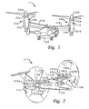
- Tilt rotor assemblies 15a and 15b are carried by wing members 17a and 17b, and are disposed at end portions 19a and 19b of wing members 17a and 17b, respectively. Wing members 17a and 17b are coupled to a fuselage 20.
- Tilt rotor assemblies 15a and 15b include nacelles 21 a and 21 b, which house the engines, transmissions, and prop rotor gear boxes that drive rotors 23a and 23b disposed on forward ends 25a and 25b of nacelles 21 a and 21 b.
- Tilt rotor assemblies 15a and 15b move or rotate relative to wing members 17a and 17b between a helicopter mode in which tilt rotor assemblies 15a and 15b are tilted upward, such that tilt rotor aircraft 11 can take off, hover, fly, and land like a conventional helicopter; and an airplane mode in which tilt rotor assemblies 15a and 15b are tilted forward, such that tilt rotor aircraft 11 flies like a conventional fixed-wing propeller driven aircraft.
- tilt rotor aircraft 1 is shown in the helicopter mode.
- Tilt rotor assemblies 115a and 115b are carried by wing members 117a and 117b, and are disposed at end portions 119a and 119b of wing members 117a and 117b, respectively. Wing members 117a and 117b are coupled to a fuselage 120.
- Tilt rotor assemblies 115a and 115b include nacelles 121 a and 121 b, which house the engines, transmissions, and prop rotor gear boxes that drive rotors 123a and 123b disposed on forward ends 125a and 125b of nacelles 121 a and 121 b.
- Tilt rotor assemblies 115a and 115b move or rotate relative to wing members 117a and 117b between a helicopter mode in which tilt rotor assemblies 115a and 115b are tilted upward, such that tilt rotor aircraft 111 can take off, hover, fly, and land like a conventional helicopter; and an airplane mode in which tilt rotor assemblies 115a and 115b are tilted forward, such that tilt rotor aircraft 111 flies like a conventional fixed-wing propeller driven aircraft.
- tilt rotor aircraft 111 is shown in the airplane mode.
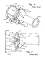
- Prior-art engine mount system 201 includes a forward mount 203 and an aft mount 205.
- Forward mount 203 is coupled between an engine 207 and a prop rotor gear box 209.
- Aft mount 205 is coupled between engine 207 and a pylon assembly (not shown, but similar to pylon assembly 410 in Figure 10 ) disposed within a nacelle (not shown, but similar to nacelle 21 b).
- a mechanical loop is formed by coupling the forward end of engine 207 to prop rotor gear box 209, by coupling prop rotor gear box 209 to the pylon assembly, and by coupling the pylon assembly to the aft end of engine 207.
- This mechanical loop is the means by which torque from the rotor (not shown, but similar to rotor 23b), also referred to as wind-up torque, is induced back into engine 207.
- Aft mount 205 is typically made of stainless steel and includes a mounting bracket 211 coupled to engine 207, and three links 213a, 213b, and 213c, each pivotally coupled between mounting bracket 211 and the pylon assembly.
- Link 213a includes a tuning means 214 to reduce the excessive torsional stiffness of aft mount 205 and to add some lateral tuning capabilities.
- Links 213a and 213b have longitudinal axes 216a and 216b, respectively, that intersect at a focal point C which is on the longitudinal center line 218 of engine 207. This arrangement makes aft mount 205 statically determinate.
- Link 213c is necessary for torque sharing, because forward mount 203 is not sufficiently tunable or strong. Because link 213c is necessary for torque sharing, it also counteracts the induced torque from the rotor that is transferred back through the engine 207 and into the pylon assembly.
- forward mount 203 includes an engine torquemeter housing 215, a gimbal ring 217, and an input quill housing 219.
- Engine torquemeter housing 215 is typically made of titanium, and includes an attachment flange 221 for coupling to the forward end of engine 207, and a forked end 223 having clevis arms 223a and 223b for coupling to the upper and lower sides of gimbal ring 217.
- Input quill housing 219 is typically made of stainless steel, and includes an attachment flange 225 for coupling to prop rotor gear box 209 (see Figure 3 ), and a forked end 227 having clevis arms 227a and 227b for coupling to the right and left sides of gimbal ring 217.
- Gimbal ring 217 is typically made of stainless steel, is coupled to clevis arms 223a and 223b of engine torquemeter housing 215 with expandable bolts 229, and Is coupled to clevis arms 227a and 227b of input quill housing 219 with expandable bolts 231.
- Forward mount 203 acts as a universal pin joint, i.e., forward mount 203 counteracts the torque generated by coupling engine 207 to prop rotor gear box 209, but forward mount 203 does not counteract any bending moments.
- Each aft mount 205, along with associated attachment hardware typically weighs about 5.4 kg (11.9 pounds).
- the total weight of aft mounts 205 can be as high as 10.8 kg (23.8 pounds) per tilt rotor aircraft 11.
- the total weight of this prior-art engine mounting system is about 51.2 kg (113 pounds) per tilt rotor aircraft 11.
- System 13 as shown in Figure 6 is for the left-hand tilt rotor assembly 15b.
- System 13 includes a forward mount 303 and a dual link aft mount 305.
- System 13 is a means of mounting a conventional engine 307 to a conventional prop rotor gear box 309 and a conventional pylon assembly (not shown, but similar to pylon assembly 410 in Figure 10 ).
- a mechanical engine-pylon loop is formed by coupling the forward end of engine 307 to prop rotor gear box 309, by coupling prop rotor gear box 309 to the forward end pylon assembly, and by coupling the aft end of the pylon assembly to the aft end of engine 307. If not for the torsional de-coupling of the present invention, rotor torque from main rotor 23b would be induced into engine 307 via the engine-pylon loop.
- Forward mount 303 is preferably chalice-shaped and made of aluminum.
- Forward mount 303 includes an elongated annular base portion 315a, an annular flexure region 315b having a reduced diameter, and an annular top portion 315c.
- Base portion 315a terminates with an attachment flange 321 a for coupling forward mount 303 to the forward end of an engine 307.
- Attachment flange 321 a includes a plurality of spaced mounting apertures 327 which receive bolts 329 for securing base portion 315a to engine 307.
- base portion 315a is elongated to house a conventional engine torquemeter. As will be explained in detail below, the length of base portion 315a may vary depending upon the application in which forward mount 303 is used.
- Top portion 315c of forward mount 303 terminates with an attachment flange 321 b for attachment to an input quill housing 319 of prop rotor gear box 309.
- Attachment flange 321 b includes a plurality of spaced mounting apertures 343 which receive bolts 341 for securing top portion 315c to input quill housing 319.
- Input quill housing 319 serves as an adapter coupling with which forward mount 303 can be coupled to prop rotor gear box 309 or any other prop rotor gear box or transmission.
- Input quill housing 319 is preferably made of aluminum, and includes a generally frusto-conical base portion 319a and an end portion 319b.
- Base portion 319a of input quill housing 319 terminates with an attachment flange 325a for coupling to prop rotor gear box 309.
- Attachment flange 325a includes a plurality of spaced mounting apertures 331 which receive bolts (not shown) for securing base portion 319a to prop rotor gear box 309.
- End portion 319b terminates with an attachment flange 325b for coupling to end portion 315c of forward mount 303.
- Attachment flange 325b includes a plurality of spaced mounting apertures 345 which receive bolts 341 for securing end portion 319b to top portion 315c of forward mount 303.
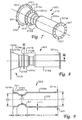
- forward mount 303 is illustrated in a cross-sectional view taken at IX-IX in Figure 8 .
- forward mount 303 is preferably hollow and chalice-shaped, having a wall thickness T1.
- Base portion 315a has a longitudinal length L1
- flexure region 315b has a longitudinal length L2
- end portion 315c has a longitudinal length L3.
- base portion 315a has an outside diameter of D1
- end portion 315c has an outside diameter of D3.
- flexure region 315b tapers radially inwardly along a longitudinal axis 320
- flexure region 315b has an outside diameter D2 and a slope S1 that vary over the length L2 of flexure region 315b.
- T1, L1, L2, L3, D1, D2, D3, and S1 may be either constant or may be varied over certain ranges or lengths. By altering the values of T1, L1, L2, L3, D1, D2, D3, and S1, or by altering the material of forward mount 303, the dynamic properties of forward mount 303 can be changed.
- aft mount 305 includes a mounting bracket 351 and links 353a and 353b.
- Mounting bracket 351 and links 353a and 353b are preferably made of steel.
- aft mount 305 may be mounted to engine 307 at any number of locations, it is preferred that mounting bracket 351 is coupled to the upper side of aft portion of engine 307.
- Links 353a and 353b are each pivotally coupled between mounting bracket 351 and a pylon assembly (not shown, but similar to pylon assembly 410 in Figure 10 ).
- Links 353a and 353b have longitudinal axes 355a and 355b, respectively, that intersect at a focal point P1 which is preferably located on a longitudinal axis 357 of engine 307.
- Aft mount 305 counteracts only vertical and lateral forces acting at longitudinal axis 357.
- Aft mount 305 does not counteract any torque about longitudinal axis 357 or any bending forces about any lateral axes or any longitudinal forces acting on engine 307, such as forces generated by engine thermal growth.
- the portion of the torque from rotor 123b which would be induced into the engine-pylon loop is de-coupled from engine 307, without the need for complicated and heavy components, such as complicated tuning links.
- forward mount 303 still functions to counteract torque applied to the transmission by the engine input shaft.
- forward mount 303 counteracts forces in all six degrees of freedom, i.e., all vertical, longitudinal, and lateral forces, and all bending moments about the vertical, longitudinal, and lateral axes.
- the size, shape, weight, and other physical properties of forward mount 303 are selectively tailored to tune the contribution of engine 307 to the dynamic response of the entire aircraft 11.
- the size, shape, and material of flexure region 315b is selectively tailored by altering T1, D2, and S1 to produce a desired dynamic response. In this manner, the contribution of engine 307 to the dynamic response of the entire aircraft 11 can be dynamically tuned without the need for heavy, complicated gimbal systems, such as those shown in Figures 3-5 .
- each forward mount 303 weighs about 7.2 kg (16.0 pounds). With one forward mount 303 on each engine 307, the total weight of forward mounts 303 is only about 14.5 kg (32.0 pounds) per aircraft 11.
- aft mount 305 along with its associated attachment hardware, weighs about 2.7 kg (6.0 pounds). With one aft mount 305 on each engine 307, the total weight of aft mounts 305 is only about 5.4 kg (12.0 pounds) per aircraft 11. Thus, the total weight of torsionally de-coupled engine mount system 13 is only about 19.9 kg (44.0 pounds) per aircraft 11. This represents a weight saving of about 31.3 kg (69.0 pounds) per aircraft, or about 61%, over the prior-art engine mounting system of Figures 3-5 described above.
- System 113 as shown in Figure 10 is for the left hand tilt rotor assembly 115b.
- System 113 includes a chalice-shaped forward mount 403 and a bi-pod triangular-shaped aft mount 405.
- System 113 is a means of mounting a conventional engine 407 to a conventional prop rotor gear box 409 and a conventional pylon assembly 410.
- Engine torque from engine 407 is transferred through prop rotor gear box 409 to a drive shaft 416 which drives rotor 123b.
- Forward mount 403 is preferably made of aluminum, and includes a base portion 415, an integral flexure region 423, and an input quill housing 419.
- Base portion 415 transitions into input quill housing 419 at flexure region 423.
- Base portion 415 terminates with an attachment flange 421 for coupling to the forward end of engine 407.
- Attachment flange 421 includes a plurality of spaced mounting apertures 427 which receive bolts 429 for securing forward mount 403 to engine 407.
- Input quill housing 419 terminates with an attachment flange 425 for coupling to prop rotor gear box 409.
- Attachment flange 425 includes a plurality of spaced mounting apertures 431 which receive bolts 433 for securing forward mount 403 to prop rotor gear box 409.
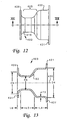
- forward mount 403 is illustrated in a cross-sectional view taken at XIII-XIII of Figure 12 .
- forward mount 403 is preferably hollow and chalice-shaped, having a wall thickness T2.
- Base portion 415 has a longitudinal length L4, flexure region 423 has a longitudinal length L5, and input quill housing 419 has a longitudinal length L6.
- base portion 415 has an outside diameter of D4 and input quill housing 423 has an outside diameter of D6. Because flexure region 423 tapers radially inwardly along a longitudinal axis 420, flexure region 423 has an outside diameter D5 and a slope S2 that vary over the length L5 of flexure region 423.
- T2, L4, L5, L6, D4, D5, D6, and S2 may be either constant or may be varied over certain ranges or lengths. By altering the values of T2, L4, L5, L6, D4, D5, D6, and S2, or by altering the material of forward mount 403, the dynamic properties of forward mount 403 can be changed.
- forward mount 403 is shown in a wire frame perspective view.
- forward mount 403 is shown in a deflected mode in which attachment flange 421 of base portion 415 is bent relative to attachment flange 425 of input quill housing 419.
- flexure region 423 deforms by straightening out on the tension side and pinching in on the compression side to accommodate this bending.
- forward mount 403 counteracts forces in all six degrees of freedom, i.e., all vertical, longitudinal, and lateral forces, and all bending moments about the vertical, longitudinal, and lateral axes.
- the size, shape, weight, and other physical properties of forward mount 403 are selectively tailored to tune the contribution of engine 407 to the dynamic response of the entire aircraft 111.
- the size, shape, and material of flexure region 423 is selectively tailored by altering T2, D5, and S2 to produce a desired dynamic response. In this manner, the contribution of engine 407 to the dynamic response of the entire aircraft 111 can be dynamically tuned without the need for heavy, complicated gimbal systems, such as those shown in Figures 3-5 .
- aft mount 405 includes a mounting bracket 451 and two triangular-shaped parallel fittings 453a and 453b.
- Mounting bracket 451 and fittings 453a and 453b are preferably made of steel.
- aft mount 405 may be mounted to engine 407 at any number of locations, it is preferred that mounting bracket 451 is coupled to the upper side of the aft portion of engine 407.
- Fittings 453a and 453b are both pivotally coupled to mounting bracket 451 by a pivot pin 461.
- Fittings 453a and 453b are both pivotally coupled to pylon assembly 410 with bolts 463a and 463b.
- bolts 461 and 463a form a line of action 455a; and bolts 461 and 463b form a line of action 455b.
- Lines of action 455a and 455b intersect at a focal point P2 which is located above the longitudinal center line 475 of engine 407.
- bolts 461 and 463a form a line of action 455c; and bolts 461 and 463b form a line of action 455d.
- Lines of action 455c and 455d intersect at a focal point P3 which is located above the longitudinal center line 475 of engine 407.
- Mounting bracket 451 and fittings 453a and 453b form a simple truss that functions like a bi-pod.
- Aft mount 405 counteracts only vertical and lateral forces acting at longitudinal axis 475.
- Aft mount 405 does not counteract any torque acting about longitudinal axis 475 or any bending forces about any lateral axes or any longitudinal forces acting on engine 407, such as forces generated by engine thermal growth.
- the portion of the torque from rotor 123b which would be induced into the engine-pylon loop is de-coupled from engine 407, without the need for complicated and heavy components, such as complicated tuning links.
- forward mount 403 still functions to counteract torque applied to the transmission by the engine input shaft.
- Figures 16A and 16B illustrate how the torsionally de-coupled engine mount system of the present invention prevents rotor torque from being induced back into the engine from the engine-pylon loop.
- FIG 16A is a wire frame schematic of a prior-art erigine-pylon combination 501 in which an engine 503 is mounted at its forward end to a prop rotor gear box (not shown) by a forward mount (not shown) and at its aft end to a pylon 505 by a torsionally redundant aft mount 507.
- Pylon 505 includes a spindle 509 that is rigidly installed in the wing of the aircraft (not shown), and a body portion 511 that carries the prop rotor gearbox and engine 503.
- the wind-up torque from the prop rotor gear box is represented by arrow T. Wind-up torque T causes spindle 509 to bend upwardly and body portion 511 to rotate upwardly.
- Figure 16B is a wire frame schematic of an engine-pylon combination 601 for the torsionally de-coupled engine mount system of the present invention in which an engine 603 is mounted at its forward end to a prop rotor gear box (not shown) by a forward mount (not shown) and at its aft end to a pylon 605 by a bi-pod mount 607.
- Pylon 605 includes a spindle 609 that is rigidly installed in the wing of the aircraft (not shown), and a body portion 611 that carries the prop rotor gearbox and engine 603.
- the wind-up torque from the prop rotor gear box is represented by arrow T.
- Wind-up torque T causes spindle 609 of bend upwardly and body portion 611 to rotate upwardly. This rotation causes the forward end of engine 603 to rotate upwardly with the prop rotor gear box.
- aft engine mount 607 is a bi-pod, the aft end of engine 603 does not undergo any torsional twisting. Thus, the lines along the longitudinal direction of engine 603 are straight.
- all of the wind-up torque T is passed back into pylon 605, and none of the wind-up torque T is induced into engine 603. This results In considerable cost and weight savings.
- engine 603 does not have to be unnecessarily over-designed to accommodate induced torque from the rotor.
Description
- The present invention relates to systems for mounting engines in aircraft. In particular, the present invention relates to systems for mounting engines in tilt rotor aircraft.
- Tilt rotor aircraft are unique in that they have tilt rotor assemblies that operate between a helicopter mode in which the tilt rotor assemblies are rotated upward allowing the tilt rotor aircraft to take off, hover, fly, and land like a conventional helicopter; and an airplane mode, in which the tilt rotor assemblies are tilted forward allowing the tilt rotor aircraft to fly like a conventional fixed-wing propeller driven aircraft. The first tilt rotor aircraft were designed strictly for military or research purposes, but now plans are being made to manufacture civilian-type tilt rotor aircraft.
- Aside from the vast differences between tilt rotor aircraft and conventional helicopters and propeller driven aircraft, there are significant differences between military-type tilt rotor aircraft and civilian-type tilt rotor aircraft. Often a design that is necessary in a military-type application is not commercially feasible in a civilian-type application. For example, certain factors, such as weight, passenger comfort, safety, and cost, must be carefully considered if a civilian-type tilt rotor aircraft program is to be successful. In addition, civilian-type tilt rotor aircraft will have to comply with a considerable amount of governmental regulation. Certain additional design considerations must be made to accommodate the civilian tilt rotor aircraft market.
- Although tilt rotor aircraft provide many unique advantages, they also present many unique challenges. One such challenge involves the mounting of the engines to the transmissions and other components in the aircraft. Because the engines in tilt rotor aircraft are mounted to pylons and transmissions located at the ends of the wings in a manner that allows rotation relative to the wings, engine mounting techniques used in conventional helicopters and propeller driven aircraft are not adequate.
- In tilt rotor aircraft, the engines and transmissions are mounted in nacelles that rotate relative to the wings of the aircraft. The rotors, transmissions, and engines are carried by pylon assemblies within the nacelles that rotate about spindles that are installed into the outboard ends of the wing members. The transmissions, also referred to as prop rotor gear boxes, are coupled to the forward ends of the pylon assemblies, and the engines are disposed beneath the pylon assemblies. The engines are coupled to the transmissions and pylons by engine mounting systems. The engine mounting systems perform several functions: they hold and support the engine in the aircraft; they counteract the torque applied to the transmission by the engine input shaft; and they play a critical role in determining the contribution of the engine to the overall dynamic response of the aircraft.
- In early designs, the engine was attached by an engine mount directly to the prop rotor gear box so that the engine extended back from the prop rotor gear box in a cantilevered fashion and hung generally parallel to and below the pylon assembly. However, it was quickly determined that support of the aft end of the engine was necessary. This was done initially with a single rigid link connected to the pylon. In later designs, the engine was attached to the prop rotor gear box by a gimbal assembly and supported at the aft end by multiple rigid links. One of the links was later modified to include a tuning means which could be used to counteract primarily lateral loads and to tune the dynamic response of the engine. An engine mount of this type is shown in
figure 3 and disclosed in "V-22 Propulsion System Design" Paper No. 91-25 presented by W.G. Sonneborn, E.O. Kaiser, C.E. Covington, and K. Wilson of Bell Helicopter Textron, Inc. at the Seventeenth European Rotorcraft Forum, Berlin, Germany, September 24-27, 1991. - Although these changes in the engine mounting system solved the problems associated with the engines being cantilevered from the prop rotor gear boxes, they introduced other problems. Most significantly, coupling the engine to both the prop rotor gear box and the pylon assembly created a mechanical loop through which torque from the main rotor could be induced into the engine at the prop rotor gear box and reacted near the aft end of the engine into the pylon. Thus, the introduction of multiple rigid links coupled near the aft end of the engine created torsional redundancy in the engine. In other words, these prior-art techniques unnecessarily allowed a portion of the rotor torque to be induced into the engine-pylon loop.
- A tilt rotor aircraft as defined in the precharacterizing portion of
independent claim 1 is known from the article "BA 609 Tiltrotor drive system", by Charles Duello, presented at the American Helicopter Society 58th Annual Forum, Montreal, Canada, June 11-13, 2002, pages 1581-1597, XP 008054334, which discloses the Bell Helicopter Textron, Inc. BA 609 tilt rotor aircraft powered by Pratt and Whitney PT6C-67A engines as disclosed in the article "Advanced Technologies Applied to PT6C-67A Tilt Rotor Engine Design" by H. Smailys et al., presented at the American Helicopter Society, 57th Annual Forum, Washington D.C., USA, May 9-11, 2001, pages 900-911, XP008054333. The BA609 mount system of the PT6C-67A engine has an annular front or forward mount which is retained in all degrees of freedom and an aft or rear mount which reacts to lateral and vertical loads. The front mount is sufficiently stiff for the bearings to clear the power turbine rotor rigid body modes, and flexible enough to tolerate installation misalignments. - The foregoing represents great strides in the design and manufacture of tilt rotor aircraft; however, many challenges remain, particularly in the area of engine mounting systems.
- In accordance with the invention there is provided a tilt rotor aircraft comprising:
- a fuselage;
- a wing member coupled to the fuselage;
- a pylon assembly pivotally coupled to the wing member;
- a transmission coupled to the pylon assembly;
- a prop rotor coupled to the transmission;
- an engine; and
- an engine mount system for supporting the engine comprising:
- an annular forward mount for coupling the engine to the transmission, and
- an aft mount for coupling the engine to the pylon assembly, wherein said annular forward mount comprises:
- an annular base portion configured for coupling to the engine, the annular base portion having a first outside diameter, and an annular region including a first part having a second outside diameter that is less than the first outside diameter and a second part forming a transition in outside diameter between the second outside diameter of the first part and the first outside diameter of the annular base portion;
- The engines are mounted at their forward ends to prop rotor gear boxes by means of simple adapter fittings and are preferably mounted at their aft ends to pylon assemblies by means of simple focused bi-pods, or delta, fittings. The forward mounts counteract forces and moments in six degrees of freedom, but the aft mounts counteract only lateral and vertical forces from the pylon assemblies. The contribution from the engines to the overall dynamic response of the aircraft is tuned by selectively tailoring the size, shape, weight, and material of the forward mounts, which are preferably chalice-shaped. In this manner, the engines are torsionally de-coupled so that no portion of the rotor torque can be induced into the engine-pylon loop, while providing stiff engine mounts that are tunable.
- The torsionally de-coupled engine mount system of the present invention provides significant advantages. Loads in the engine mounts are significantly reduced. This allows the use of fewer parts that are less complicated and that weight less. This leads to commensurate cost and weight savings. For example, weight and cost of the system in the military-type tilt rotor aircraft application can be reduced by over 65%. The engine and pylon assembly can also be lighter, because with the present invention these components do have to be designed for high induced torque from the rotors. Dynamic analysis and tuning of the system is facilitated by simple structure and load paths. Dynamic and static problems are diminished by the significant reduction in system complexity. The system eliminates the need for highly loaded gimbal mounts and multiple link attachments.
- The novel features believed characteristic of the invention are set forth in the appended claims. However, the invention itself, as well as, a preferred mode of use, and further objectives and advantages thereof, will best be understood by reference to the following detailed description when read in conjunction with the accompanying drawings, wherein:
-
Figure 1 is a perspective view of a military-type tilt rotor aircraft having a torsionally de-coupled engine mount system according to the present invention; -
Figure 2 is a perspective view of a civilian-type tilt rotor aircraft having a torsionally de-coupled engine mount system according to the present invention; -
Figure 3 is a partially exploded perspective view of a prior-art engine mount system for use on military-type tilt rotor aircraft similar to the aircraft ofFigure 1 ; -
Figure 4 is a perspective view of the forward mount of the prior-art engine mount system ofFigure 3 ; -
Figure 5 is a side view of the forward mount ofFigure 4 ; -
Figure 6 is a perspective view of the torsionally de-coupled engine mount system of the military-type tilt rotor aircraft ofFigure 1 ; -
Figure 7 is a perspective view of the forward mount of the engine mount system ofFigure 6 ; -
Figure 8 is a side view of the forward mount ofFigure 7 ; -
Figure 9 is a cross-sectional view of the forward mount ofFigure 6 taken at IX-IX inFigure 8 ; -
Figure 10 is a perspective view of the torsionally de-coupled engine mount system of the civilian-type tilt rotor aircraft ofFigure 2 ; -
Figure 11 is a perspective view of the forward mount of the engine mount system ofFigure 10 ; -
Figure 12 is a side view of the forward mount ofFigure 11 ; -
Figure 13 is a cross-sectional view of the forward mount ofFigure 10 taken at XIII-XIII inFigure 12 ; -
Figure 14 is an enlarged wire frame perspective view of the forward mount ofFigure 11 in a deflected mode; -
Figure 15 is an enlarged perspective view of the aft mount of the engine mount system ofFigure 10 ; and -
Figures 16A and 16B are wire frame schematics comparing the torsionally de-coupled engine mount system according to the present invention with a torsionally redundant engine mount system. - Referring to
Figure 1 in the drawings, a military-typetilt rotor aircraft 11 having a torsionally de-coupledengine mount system 13 according to the present invention is illustrated.Tilt rotor assemblies 15a and 15b are carried by wing members 17a and 17b, and are disposed atend portions 19a and 19b of wing members 17a and 17b, respectively. Wing members 17a and 17b are coupled to afuselage 20.Tilt rotor assemblies 15a and 15b includenacelles 21 a and 21 b, which house the engines, transmissions, and prop rotor gear boxes that driverotors nacelles 21 a and 21 b. -
Tilt rotor assemblies 15a and 15b move or rotate relative to wing members 17a and 17b between a helicopter mode in which tiltrotor assemblies 15a and 15b are tilted upward, such thattilt rotor aircraft 11 can take off, hover, fly, and land like a conventional helicopter; and an airplane mode in which tiltrotor assemblies 15a and 15b are tilted forward, such thattilt rotor aircraft 11 flies like a conventional fixed-wing propeller driven aircraft. InFigure 1 ,tilt rotor aircraft 1 is shown in the helicopter mode. - Referring now to
Figure 2 in the drawings, a civilian-typetilt rotor aircraft 111 having a torsionally de-coupledengine mount system 113 according to the present invention is illustrated.Tilt rotor assemblies 115a and 115b are carried by wing members 117a and 117b, and are disposed at end portions 119a and 119b of wing members 117a and 117b, respectively. Wing members 117a and 117b are coupled to afuselage 120.Tilt rotor assemblies 115a and 115b includenacelles rotors 123a and 123b disposed on forward ends 125a and 125b ofnacelles -
Tilt rotor assemblies 115a and 115b move or rotate relative to wing members 117a and 117b between a helicopter mode in which tiltrotor assemblies 115a and 115b are tilted upward, such thattilt rotor aircraft 111 can take off, hover, fly, and land like a conventional helicopter; and an airplane mode in which tiltrotor assemblies 115a and 115b are tilted forward, such thattilt rotor aircraft 111 flies like a conventional fixed-wing propeller driven aircraft. InFigure 2 ,tilt rotor aircraft 111 is shown in the airplane mode. - Referring now to
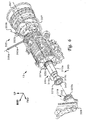
Figure 3 in the drawings, a prior-artengine mount system 201, as would be used on the left side of a military-type tilt rotor aircraft similar to the military-type aircraft ofFigure 1 , is illustrated. Prior-artengine mount system 201 includes aforward mount 203 and anaft mount 205.Forward mount 203 is coupled between anengine 207 and a proprotor gear box 209.Aft mount 205 is coupled betweenengine 207 and a pylon assembly (not shown, but similar topylon assembly 410 inFigure 10 ) disposed within a nacelle (not shown, but similar tonacelle 21 b). A mechanical loop is formed by coupling the forward end ofengine 207 to proprotor gear box 209, by coupling proprotor gear box 209 to the pylon assembly, and by coupling the pylon assembly to the aft end ofengine 207. This mechanical loop is the means by which torque from the rotor (not shown, but similar torotor 23b), also referred to as wind-up torque, is induced back intoengine 207. -
Aft mount 205 is typically made of stainless steel and includes a mountingbracket 211 coupled toengine 207, and threelinks bracket 211 and the pylon assembly. Link 213a includes a tuning means 214 to reduce the excessive torsional stiffness ofaft mount 205 and to add some lateral tuning capabilities.Links 213a and 213b have longitudinal axes 216a and 216b, respectively, that intersect at a focal point C which is on thelongitudinal center line 218 ofengine 207. This arrangement makesaft mount 205 statically determinate.Link 213c is necessary for torque sharing, becauseforward mount 203 is not sufficiently tunable or strong. Becauselink 213c is necessary for torque sharing, it also counteracts the induced torque from the rotor that is transferred back through theengine 207 and into the pylon assembly. - Referring now also to
Figures 4 and 5 in the drawings,forward mount 203 includes anengine torquemeter housing 215, agimbal ring 217, and aninput quill housing 219.Engine torquemeter housing 215 is typically made of titanium, and includes anattachment flange 221 for coupling to the forward end ofengine 207, and a forkedend 223 having clevisarms gimbal ring 217.Input quill housing 219 is typically made of stainless steel, and includes anattachment flange 225 for coupling to prop rotor gear box 209 (seeFigure 3 ), and a forkedend 227 having clevisarms 227a and 227b for coupling to the right and left sides ofgimbal ring 217.Gimbal ring 217 is typically made of stainless steel, is coupled to clevisarms engine torquemeter housing 215 withexpandable bolts 229, and Is coupled to clevisarms 227a and 227b ofinput quill housing 219 withexpandable bolts 231. Forward mount 203 acts as a universal pin joint, i.e.,forward mount 203 counteracts the torque generated bycoupling engine 207 to proprotor gear box 209, but forward mount 203 does not counteract any bending moments. Eachforward mount 203, along with associated attachment hardware, typically weighs about 20.2 kg (44.6 pounds). With oneforward mount 203 on eachengine 207, the total weight of forward mounts 203 can be as high as 40.4 kg (89.2 pounds) pertilt rotor aircraft 11. Eachaft mount 205, along with associated attachment hardware, typically weighs about 5.4 kg (11.9 pounds). With oneaft mount 205 on eachengine 207, the total weight of aft mounts 205 can be as high as 10.8 kg (23.8 pounds) pertilt rotor aircraft 11. Thus, the total weight of this prior-art engine mounting system is about 51.2 kg (113 pounds) pertilt rotor aircraft 11. - Referring now to
Figures 6-9 in the drawings, the preferred embodiment of the torsionally de-coupledengine mount system 13 for military-typetilt rotor aircraft 11 ofFigure 1 , is illustrated.System 13 as shown inFigure 6 is for the left-handtilt rotor assembly 15b.System 13 includes aforward mount 303 and a dual link aftmount 305.System 13 is a means of mounting aconventional engine 307 to a conventional proprotor gear box 309 and a conventional pylon assembly (not shown, but similar topylon assembly 410 inFigure 10 ). A mechanical engine-pylon loop is formed by coupling the forward end ofengine 307 to proprotor gear box 309, by coupling proprotor gear box 309 to the forward end pylon assembly, and by coupling the aft end of the pylon assembly to the aft end ofengine 307. If not for the torsional de-coupling of the present invention, rotor torque frommain rotor 23b would be induced intoengine 307 via the engine-pylon loop. -
Forward mount 303 is preferably chalice-shaped and made of aluminum.Forward mount 303 includes an elongated annular base portion 315a, anannular flexure region 315b having a reduced diameter, and an annulartop portion 315c. Base portion 315a terminates with anattachment flange 321 a for coupling forward mount 303 to the forward end of anengine 307.Attachment flange 321 a includes a plurality of spaced mountingapertures 327 which receivebolts 329 for securing base portion 315a toengine 307. In the preferred embodiment, base portion 315a is elongated to house a conventional engine torquemeter. As will be explained in detail below, the length of base portion 315a may vary depending upon the application in which forward mount 303 is used. -
Top portion 315c offorward mount 303 terminates with anattachment flange 321 b for attachment to aninput quill housing 319 of proprotor gear box 309.Attachment flange 321 b includes a plurality of spaced mountingapertures 343 which receivebolts 341 for securingtop portion 315c to inputquill housing 319.Input quill housing 319 serves as an adapter coupling with which forward mount 303 can be coupled to proprotor gear box 309 or any other prop rotor gear box or transmission.Input quill housing 319 is preferably made of aluminum, and includes a generally frusto-conical base portion 319a and an end portion 319b. - Base portion 319a of
input quill housing 319 terminates with an attachment flange 325a for coupling to proprotor gear box 309. Attachment flange 325a includes a plurality of spaced mountingapertures 331 which receive bolts (not shown) for securing base portion 319a to proprotor gear box 309. End portion 319b terminates with anattachment flange 325b for coupling to endportion 315c offorward mount 303.Attachment flange 325b includes a plurality of spaced mountingapertures 345 which receivebolts 341 for securing end portion 319b totop portion 315c offorward mount 303. Thus,forward mount 303 andinput quill housing 319 are coupled together atattachment flanges bolts 341 that pass through mountingapertures - In
Figure 9 ,forward mount 303 is illustrated in a cross-sectional view taken at IX-IX inFigure 8 . As is shown,forward mount 303 is preferably hollow and chalice-shaped, having a wall thickness T1. Base portion 315a has a longitudinal length L1,flexure region 315b has a longitudinal length L2, andend portion 315c has a longitudinal length L3. In addition, base portion 315a has an outside diameter of D1 andend portion 315c has an outside diameter of D3. Becauseflexure region 315b tapers radially inwardly along alongitudinal axis 320,flexure region 315b has an outside diameter D2 and a slope S1 that vary over the length L2 offlexure region 315b. It should be understood that T1, L1, L2, L3, D1, D2, D3, and S1 may be either constant or may be varied over certain ranges or lengths. By altering the values of T1, L1, L2, L3, D1, D2, D3, and S1, or by altering the material offorward mount 303, the dynamic properties offorward mount 303 can be changed. - As shown in
Figure 6 ,aft mount 305 includes a mounting bracket 351 andlinks 353a and 353b. Mounting bracket 351 andlinks 353a and 353b are preferably made of steel. Althoughaft mount 305 may be mounted toengine 307 at any number of locations, it is preferred that mounting bracket 351 is coupled to the upper side of aft portion ofengine 307.Links 353a and 353b are each pivotally coupled between mounting bracket 351 and a pylon assembly (not shown, but similar topylon assembly 410 inFigure 10 ).Links 353a and 353b havelongitudinal axes 355a and 355b, respectively, that intersect at a focal point P1 which is preferably located on alongitudinal axis 357 ofengine 307. Because the induced torque fromrotor 23b (seeFigure 1 ) can only be transferred back throughengine 307 into the pylon assembly throughlinks 353a and 353b, and becauselinks 353a and 353b have a focal point P1 that lies onlongitudinal axis 357, the induced torque fromrotor 23b is eliminated and has no effect on the engine torque ofengine 307. This configuration ensures that no portion of the torque fromrotor 23b is induced intoengine 307 via the engine-pylon loop. -
Aft mount 305 counteracts only vertical and lateral forces acting atlongitudinal axis 357.Aft mount 305 does not counteract any torque aboutlongitudinal axis 357 or any bending forces about any lateral axes or any longitudinal forces acting onengine 307, such as forces generated by engine thermal growth. As such, the portion of the torque fromrotor 123b which would be induced into the engine-pylon loop is de-coupled fromengine 307, without the need for complicated and heavy components, such as complicated tuning links. However,forward mount 303 still functions to counteract torque applied to the transmission by the engine input shaft. - In operation,
forward mount 303 counteracts forces in all six degrees of freedom, i.e., all vertical, longitudinal, and lateral forces, and all bending moments about the vertical, longitudinal, and lateral axes. According to the present invention, the size, shape, weight, and other physical properties offorward mount 303 are selectively tailored to tune the contribution ofengine 307 to the dynamic response of theentire aircraft 11. In particular, the size, shape, and material offlexure region 315b is selectively tailored by altering T1, D2, and S1 to produce a desired dynamic response. In this manner, the contribution ofengine 307 to the dynamic response of theentire aircraft 11 can be dynamically tuned without the need for heavy, complicated gimbal systems, such as those shown inFigures 3-5 . - In the preferred embodiment of the present invention for the military-type tilt rotor aircraft of
Figure 1 , eachforward mount 303, along with its associated attachment hardware, weighs about 7.2 kg (16.0 pounds). With oneforward mount 303 on eachengine 307, the total weight of forward mounts 303 is only about 14.5 kg (32.0 pounds) peraircraft 11. In the preferred embodiment,aft mount 305, along with its associated attachment hardware, weighs about 2.7 kg (6.0 pounds). With oneaft mount 305 on eachengine 307, the total weight of aft mounts 305 is only about 5.4 kg (12.0 pounds) peraircraft 11. Thus, the total weight of torsionally de-coupledengine mount system 13 is only about 19.9 kg (44.0 pounds) peraircraft 11. This represents a weight saving of about 31.3 kg (69.0 pounds) per aircraft, or about 61%, over the prior-art engine mounting system ofFigures 3-5 described above. - Referring now to
Figures 10-15 in the drawings, the preferred embodiment of the torsionally de-coupledengine mount system 113 according to the present invention for the civilian-typetilt rotor aircraft 111 ofFigure 2 , is illustrated.System 113 as shown inFigure 10 is for the left handtilt rotor assembly 115b.System 113 includes a chalice-shapedforward mount 403 and a bi-pod triangular-shapedaft mount 405.System 113 is a means of mounting aconventional engine 407 to a conventional proprotor gear box 409 and aconventional pylon assembly 410. Engine torque fromengine 407 is transferred through proprotor gear box 409 to adrive shaft 416 which drivesrotor 123b. -
Forward mount 403 is preferably made of aluminum, and includes abase portion 415, anintegral flexure region 423, and aninput quill housing 419.Base portion 415 transitions intoinput quill housing 419 atflexure region 423.Base portion 415 terminates with anattachment flange 421 for coupling to the forward end ofengine 407.Attachment flange 421 includes a plurality of spaced mountingapertures 427 which receivebolts 429 for securing forward mount 403 toengine 407.Input quill housing 419 terminates with anattachment flange 425 for coupling to proprotor gear box 409.Attachment flange 425 includes a plurality of spaced mountingapertures 431 which receivebolts 433 for securing forward mount 403 to proprotor gear box 409. - In
Figure 13 ,forward mount 403 is illustrated in a cross-sectional view taken at XIII-XIII ofFigure 12 . As is shown,forward mount 403 is preferably hollow and chalice-shaped, having a wall thickness T2.Base portion 415 has a longitudinal length L4,flexure region 423 has a longitudinal length L5, andinput quill housing 419 has a longitudinal length L6. In addition,base portion 415 has an outside diameter of D4 andinput quill housing 423 has an outside diameter of D6. Becauseflexure region 423 tapers radially inwardly along alongitudinal axis 420,flexure region 423 has an outside diameter D5 and a slope S2 that vary over the length L5 offlexure region 423. It should be understood that T2, L4, L5, L6, D4, D5, D6, and S2 may be either constant or may be varied over certain ranges or lengths. By altering the values of T2, L4, L5, L6, D4, D5, D6, and S2, or by altering the material offorward mount 403, the dynamic properties offorward mount 403 can be changed. - In
Figure 14 ,forward mount 403 is shown in a wire frame perspective view. In this view,forward mount 403 is shown in a deflected mode in whichattachment flange 421 ofbase portion 415 is bent relative toattachment flange 425 ofinput quill housing 419. As is shown,flexure region 423 deforms by straightening out on the tension side and pinching in on the compression side to accommodate this bending. In this manner,forward mount 403 counteracts forces in all six degrees of freedom, i.e., all vertical, longitudinal, and lateral forces, and all bending moments about the vertical, longitudinal, and lateral axes. According to the present invention, the size, shape, weight, and other physical properties offorward mount 403 are selectively tailored to tune the contribution ofengine 407 to the dynamic response of theentire aircraft 111. In particular, the size, shape, and material offlexure region 423 is selectively tailored by altering T2, D5, and S2 to produce a desired dynamic response. In this manner, the contribution ofengine 407 to the dynamic response of theentire aircraft 111 can be dynamically tuned without the need for heavy, complicated gimbal systems, such as those shown inFigures 3-5 . - As shown in
Figure 15 ,aft mount 405 includes a mountingbracket 451 and two triangular-shapedparallel fittings bracket 451 andfittings aft mount 405 may be mounted toengine 407 at any number of locations, it is preferred that mountingbracket 451 is coupled to the upper side of the aft portion ofengine 407.Fittings bracket 451 by apivot pin 461.Fittings pylon assembly 410 withbolts bolts action 455a; andbolts action 455b. Lines ofaction longitudinal center line 475 ofengine 407. In a similar fashion, for fitting 453b,bolts action 455c; andbolts action 455d. Lines ofaction longitudinal center line 475 ofengine 407. Mountingbracket 451 andfittings - Because the induced torque from
rotor 123b (seeFigure 2 ) can only be transferred back throughengine 407 intopylon assembly 410 throughfittings fittings longitudinal axis 475, the induced torque fromrotor 123b is eliminated and has no effect on the engine torque ofengine 407. Because focal points P2 and P3 are not necessarily located exactly onlongitudinal axis 475, a small amount of torque is transferred toengine 407 due to the offset of lateral load on focal points P2 and P3 ofaft mount 405 from the enginelongitudinal axis 475. However, because the lateral load is comparatively small, this torque is negligible compared to the torque that would be induced intoengine 407 without the torsional de-coupling provided byaft mount 405. -
Aft mount 405 counteracts only vertical and lateral forces acting atlongitudinal axis 475.Aft mount 405 does not counteract any torque acting aboutlongitudinal axis 475 or any bending forces about any lateral axes or any longitudinal forces acting onengine 407, such as forces generated by engine thermal growth. As such, the portion of the torque fromrotor 123b which would be induced into the engine-pylon loop is de-coupled fromengine 407, without the need for complicated and heavy components, such as complicated tuning links. However,forward mount 403 still functions to counteract torque applied to the transmission by the engine input shaft. - Referring now to
Figures 16A and 16B in the drawings, the advantages of the torsionally de-coupledengine mount system 13 of the present invention are illustrated.Figures 16A and 16B illustrate how the torsionally de-coupled engine mount system of the present invention prevents rotor torque from being induced back into the engine from the engine-pylon loop. -
Figure 16A is a wire frame schematic of a prior-art erigine-pylon combination 501 in which anengine 503 is mounted at its forward end to a prop rotor gear box (not shown) by a forward mount (not shown) and at its aft end to apylon 505 by a torsionally redundantaft mount 507.Pylon 505 includes aspindle 509 that is rigidly installed in the wing of the aircraft (not shown), and abody portion 511 that carries the prop rotor gearbox andengine 503. In this view, the wind-up torque from the prop rotor gear box is represented by arrow T. Wind-up torque T causesspindle 509 to bend upwardly andbody portion 511 to rotate upwardly. This rotation causes the forward end ofengine 503 to rotate upwardly with the prop rotor gear box. However, becauseaft engine mount 507 is torsionally redundant and rigidly mounted topylon 505, the aft end ofengine 503 undergoes torsional twisting, which is represented by the curved lines along the longitudinal direction ofengine 503. In this configuration, about 80% of the wind-up torque T is passed back intopylon 505, but about 20% of the wind-up torque T, is induced intoengine 503. This additional torque onengine 503 is undesirable. - On the other hand,
Figure 16B is a wire frame schematic of an engine-pylon combination 601 for the torsionally de-coupled engine mount system of the present invention in which anengine 603 is mounted at its forward end to a prop rotor gear box (not shown) by a forward mount (not shown) and at its aft end to apylon 605 by abi-pod mount 607.Pylon 605 includes aspindle 609 that is rigidly installed in the wing of the aircraft (not shown), and abody portion 611 that carries the prop rotor gearbox andengine 603. As inFigure 16A , the wind-up torque from the prop rotor gear box is represented by arrow T. Wind-up torque T causesspindle 609 of bend upwardly andbody portion 611 to rotate upwardly. This rotation causes the forward end ofengine 603 to rotate upwardly with the prop rotor gear box. However, becauseaft engine mount 607 is a bi-pod, the aft end ofengine 603 does not undergo any torsional twisting. Thus, the lines along the longitudinal direction ofengine 603 are straight. By using the torsionally de-coupled engine mount system of the present invention, all of the wind-up torque T is passed back intopylon 605, and none of the wind-up torque T is induced intoengine 603. This results In considerable cost and weight savings. In addition,engine 603 does not have to be unnecessarily over-designed to accommodate induced torque from the rotor. - It is apparent that an invention with significant advantages has been described and illustrated. Although the present invention is shown in a limited number of forms, it is not limited to just these forms, but is amenable to various changes and modifications without departing from the scope of the claims.
Claims (10)
- A tilt rotor aircraft (11:111) comprising:a fuselage (20; 120);a wing member (17a; 117a) coupled to the fuselage;a pylon assembly (410) pivotally coupled to the wing member;a transmission (309; 409) coupled to the pylon assembly;a prop rotor (23a; 123a) coupled to the transmission;an engine (307; 407); andan engine mount system (13; 113) for supporting the engine comprising:characterized in that the annular region is an annular flexure region, and that the contribution from the engine (307; 407) to the dynamic response of the tilt rotor aircraft (11; 111) is determined by selectively tailoring the physical characteristics of the flexure region, said physical characteristics comprising the second outside diameter (D2; D5) of said first part, a constant or varying slope (S1; S2) in said second part forming said transition between the first and second outside diameters (D1; D4; D2; D5), and a wall thickness (T1; T2) of the annular forward mount (303; 403).an annular forward mount (303; 403) for coupling the engine to the transmission, andan aft mount (305; 405) for coupling the engine to the pylon assembly, wherein said annular forward mount (303; 403) comprises:an annular base portion (315a; 415) configured for coupling to the engine (307; 407), the annular base portion having a first outside diameter (D1; D4), and an annular region (315b; 423) including a first part having a second outside diameter (D2; D5) that is less than the first outside .diameter (D1; D4) and a second part forming a transition in outside diameter between the second outside diameter (D2; D5) of the first part and the first outside diameter (D1; D4) of the annular base portion (315a; 415);
- The tilt rotor aircraft (11) according to claim 1, characterized in that the forward mount (303) further comprises an annular top portion (315c) configured for coupling to the transmission (309).
- The tilt rotor aircraft (11) according to claim 1, characterized in that the forward mount (303) is configured to house an engine torquemeter.
- The tilt rotor aircraft (11; 111) according to claim 1, characterized in that the forward mount (303; 403) is configured in the shape of a chalice.
- The tilt rotor aircraft (11; 111) according to claim 1, characterized in that torque from the prop rotor (23a; 123a) is prevented from being induced into the engine (307; 407) by the aft mount (305; 405).
- The tilt rotor aircraft (111) according to claim 5, characterized in that the aft mount (405) is a bipod disposed in a plane generally transverse to the longitudinal axis (475) of the engine.
- The tilt rotor aircraft (11) according to claim 5, characterized in that the aft mount (305) comprises:at least one pylon mounting bracket disposed on the pylon assembly;at least one engine mounting bracket (351) disposed on the engine; anda plurality of rigid links (353a, 353b), each link being coupled to both the pylon mounting bracket and the engine mounting bracket (351), such that the links form a focal point (P1) located near the longitudinal axis (357) of the engine (307).
- The tilt rotor aircraft (111) according to claim 5, characterized in that the aft mount (405) is attached to the pylon assembly (410) at two points and attached to the engine (407) at one point, such that the aft mount (405) forms a bipod assembly disposed in a plane generally transverse to the longitudinal axis (457) of the engine (407).
- The tilt rotor aircraft (11; 111) according to claim 1, characterized in that the aft mount (305; 405) is attached to the engine (307; 407) on an upper side of the engine.
- The tilt rotor aircraft (111) according to claim 5, characterized in that the aft mount (405) comprises:a first mounting bracket attached to the pylon assembly (410);a second mounting bracket (451) attached to the engine (407); anda pair of parallel rigid plates (453a, 453b), each plate being disposed in a plane generally transverse to the longitudinal axis (475) of the engine (407), each plate being pivotally coupled at two points to the pylon assembly (410) and at one point to the engine (407).
Applications Claiming Priority (1)
| Application Number | Priority Date | Filing Date | Title |
|---|---|---|---|
| PCT/US2002/029509 WO2004026689A1 (en) | 2002-09-17 | 2002-09-17 | Torsionally de-coupled engine mount system |
Publications (3)
| Publication Number | Publication Date |
|---|---|
| EP1539573A1 EP1539573A1 (en) | 2005-06-15 |
| EP1539573A4 EP1539573A4 (en) | 2005-12-14 |
| EP1539573B1 true EP1539573B1 (en) | 2008-08-06 |
Family
ID=32028451
Family Applications (1)
| Application Number | Title | Priority Date | Filing Date |
|---|---|---|---|
| EP02761698A Expired - Lifetime EP1539573B1 (en) | 2002-09-17 | 2002-09-17 | Torsionally de-coupled engine mount system |
Country Status (5)
| Country | Link |
|---|---|
| US (2) | US7594623B2 (en) |
| EP (1) | EP1539573B1 (en) |
| CA (1) | CA2496755C (en) |
| DE (2) | DE02761698T1 (en) |
| WO (1) | WO2004026689A1 (en) |
Families Citing this family (12)
| Publication number | Priority date | Publication date | Assignee | Title |
|---|---|---|---|---|
| FR2941754B1 (en) * | 2009-01-30 | 2011-01-14 | Eurocopter France | GAME RETRACTABLE COUPLING, ROTOR AND ROTATING SAIL AIRCRAFT |
| CN101837195B (en) * | 2010-01-21 | 2012-02-08 | 罗之洪 | Model airplane with vertical takeoff and landing |
| EP2390180B1 (en) | 2010-05-27 | 2013-02-13 | AGUSTAWESTLAND S.p.A. | Non-rotating universal joint for a helicopter drive unit |
| US10252490B2 (en) | 2011-07-18 | 2019-04-09 | Rilco Manufacturing Company, Inc. | Method and system for reinforced pipe insulation |
| US8950724B2 (en) | 2012-06-28 | 2015-02-10 | Solar Turbines Inc. | Turbine engine mounting system and method |
| WO2014070640A1 (en) * | 2012-11-02 | 2014-05-08 | United Technologies Corporation | Redundant mount system |
| US9394829B2 (en) | 2013-03-05 | 2016-07-19 | Solar Turbines Incorporated | System and method for aligning a gas turbine engine |
| US9879768B2 (en) * | 2013-12-11 | 2018-01-30 | Velos Rotors Llc | Multi-electric motor driven synchronous gearbox assembly with motor failure mechanism |
| US10518891B2 (en) | 2014-11-21 | 2019-12-31 | General Electric Company | Turbine engine assembly and method of manufacturing thereof |
| US10377502B2 (en) * | 2016-02-01 | 2019-08-13 | Bell Helicopter Textron Inc. | Beam springs for aircraft engine mount assemblies |
| PL233045B1 (en) * | 2017-04-07 | 2019-08-30 | Gen Electric | System and method for coupling of the machine complex with its base |
| US11077937B1 (en) | 2018-06-22 | 2021-08-03 | Transcend Air Corporation | Vertical take-off and landing (VTOL) tilt-wing passenger aircraft |
Family Cites Families (33)
| Publication number | Priority date | Publication date | Assignee | Title |
|---|---|---|---|---|
| US2368702A (en) * | 1943-04-08 | 1945-02-06 | Raymond D Bourne | Streamlined hinge line for aircraft |
| US2461745A (en) * | 1944-12-28 | 1949-02-15 | United Aircraft Corp | Hinge structure for aircraft surfaces |
| US2718756A (en) * | 1951-06-14 | 1955-09-27 | Gen Motors Corp | Mounting and supporting structure for aircraft gas turbine power plants having reduction gearing |
| US2841344A (en) * | 1955-11-28 | 1958-07-01 | Stroukoff Michael | Boundary layer control |
| DE1292501B (en) | 1961-09-29 | 1969-04-10 | Gen Electric | Mounting system for a turbine propeller engine on an airframe |
| US3288404A (en) | 1964-08-24 | 1966-11-29 | Lord Corp | Engine mounting system |
| US3374971A (en) * | 1965-08-02 | 1968-03-26 | American Standard Inc | Fluid dynamic drag reduction |
| US3439888A (en) * | 1966-12-30 | 1969-04-22 | Boeing Co | Aircraft propulsion mounting arrangement |
| US3412962A (en) * | 1967-04-10 | 1968-11-26 | Claud R. Killian | Retractable air drag reducing aircraft attachment |
| US3582649A (en) * | 1968-10-21 | 1971-06-01 | Varian Associates | Retarding field electron diffraction spectrometer having improved resolution |
| US3681600A (en) * | 1969-10-24 | 1972-08-01 | Perkin Elmer Corp | Retarding field electron spectrometer |
| US3836100A (en) * | 1973-06-13 | 1974-09-17 | United Aircraft Corp | Engine mounting arrangement |
| US3907220A (en) * | 1974-03-14 | 1975-09-23 | United Aircraft Corp | Rear engine redundant mount |
| GB2018942B (en) * | 1978-03-20 | 1982-06-03 | Aerospatiale | Multi-directional suspension means |
| DE3149629C1 (en) * | 1981-12-15 | 1983-04-21 | Messerschmitt-Bölkow-Blohm GmbH, 8000 München | Device for sealing an air gap on an aircraft flap |
| DE3342421A1 (en) * | 1983-11-24 | 1985-06-05 | Messerschmitt-Bölkow-Blohm GmbH, 8012 Ottobrunn | METHOD FOR THE STABILIZING INFLUENCE OF DETACHED LAMINARY BORDER LAYERS |
| US4829850A (en) * | 1987-02-25 | 1989-05-16 | Soloy Dual Pac, Inc. | Multiple engine drive for single output shaft and combining gearbox therefor |
| DE3708596A1 (en) * | 1987-03-17 | 1988-09-29 | Mtu Muenchen Gmbh | GAS TURBINE SYSTEM FOR HELICOPTERS |
| FR2676707B1 (en) * | 1991-05-23 | 1993-08-13 | Snecma | NACELLE FOR SUSPENDING UNDER THE WING OF AN AIRCRAFT A TURBO-JET GROUP OF THE DOUBLE FLOW TYPE. |
| US5794893A (en) * | 1995-06-07 | 1998-08-18 | Northrop Grumman Corporation | Elastomeric transition for aircraft control surface |
| FR2738034B1 (en) * | 1995-08-23 | 1997-09-19 | Snecma | DEVICE FOR SUSPENDING A TURBOPROPELLER |
| GB2313580B (en) * | 1996-05-31 | 2000-02-23 | Astovl Limited | An aircraft power plant |
| US5823470A (en) * | 1996-07-16 | 1998-10-20 | Mcdonnell Douglas Helicopter Co. | Split torque proprotor transmission |
| FR2755944B1 (en) * | 1996-11-21 | 1998-12-24 | Snecma | REDUNDANT FRONT SUSPENSION FOR TURBOMACHINE |
| US6095456A (en) * | 1996-12-23 | 2000-08-01 | The Boeing Company | Strut-wing interface having dual upper links |
| US5873547A (en) * | 1997-05-20 | 1999-02-23 | The Boeing Company | Aircraft engine thrust mount |
| FR2770486B1 (en) * | 1997-11-06 | 2000-01-28 | Aerospatiale | DEVICE FOR HANGING AN ENGINE ON AN AIRCRAFT |
| US6145791A (en) * | 1998-01-09 | 2000-11-14 | Northrop Grumman Corporation | Elastomeric transition for aircraft control surface |
| US6068219A (en) * | 1998-04-13 | 2000-05-30 | Northrop Grumman Corporation | Single surface multi axis aircraft control |
| US6260351B1 (en) * | 1998-12-10 | 2001-07-17 | United Technologies Corporation | Controlled spring rate gearbox mount |
| FR2791634B1 (en) * | 1999-03-30 | 2001-06-15 | Eurocopter France | IMPROVEMENTS ON TILTING ROTOR CONVERTIBLE AIRCRAFT |
| FR2793768B1 (en) * | 1999-05-17 | 2001-09-07 | Aerospatiale Airbus | DEVICE FOR MOUNTING ON A MAT A PROPULSIVE AIRCRAFT ASSEMBLY AND MAT ADAPTED TO THIS DEVICE |
| US6545277B1 (en) * | 2000-08-15 | 2003-04-08 | Applied Materials, Inc. | High efficiency, enhanced detecting in-lens light guide scintillator detector for SEM |
-
2002
- 2002-09-17 US US10/528,213 patent/US7594623B2/en active Active
- 2002-09-17 WO PCT/US2002/029509 patent/WO2004026689A1/en active Application Filing
- 2002-09-17 EP EP02761698A patent/EP1539573B1/en not_active Expired - Lifetime
- 2002-09-17 CA CA2496755A patent/CA2496755C/en not_active Expired - Lifetime
- 2002-09-17 DE DE02761698T patent/DE02761698T1/en active Pending
- 2002-09-17 DE DE60228137T patent/DE60228137D1/de not_active Expired - Lifetime
-
2009
- 2009-09-28 US US12/568,442 patent/US7950605B2/en not_active Expired - Fee Related
Also Published As
| Publication number | Publication date |
|---|---|
| US7950605B2 (en) | 2011-05-31 |
| US20060151665A1 (en) | 2006-07-13 |
| EP1539573A1 (en) | 2005-06-15 |
| DE02761698T1 (en) | 2005-11-10 |
| US7594623B2 (en) | 2009-09-29 |
| US20100012775A1 (en) | 2010-01-21 |
| CA2496755C (en) | 2011-03-15 |
| WO2004026689A1 (en) | 2004-04-01 |
| EP1539573A4 (en) | 2005-12-14 |
| DE60228137D1 (en) | 2008-09-18 |
| CA2496755A1 (en) | 2004-04-01 |
Similar Documents
| Publication | Publication Date | Title |
|---|---|---|
| US7950605B2 (en) | Torsionally de-coupled engine mount system | |
| US4821980A (en) | Vibration isolating engine mount | |
| US10392098B2 (en) | High stiffness hub assemblies for rotor systems | |
| US4854525A (en) | Engine mounting assembly | |
| US7695249B2 (en) | Bearingless rotor blade assembly for a high speed rotary-wing aircraft | |
| US7264199B2 (en) | Unloaded lift offset rotor system for a helicopter | |
| US5263821A (en) | Mid-beam jointed reconfigurable bearingless main rotor assembly | |
| US5064144A (en) | Engine mounting assembly | |
| US7530790B2 (en) | Rotor blade folding system | |
| US10472057B2 (en) | Rotor assembly with high lock-number blades | |
| US11148792B2 (en) | Compound helicopter with a fixed wing arrangement | |
| US9592899B2 (en) | Rotary wing aircraft with a multiple beam tail | |
| CA2374652C (en) | Multi-bladed tail rotor hub design for coriolis relief | |
| EP3421361B1 (en) | Articulated rotor systems with pitch independent damping | |
| US5655879A (en) | Mounting arrangement for variable diameter rotor blade assemblies | |
| US5028001A (en) | Method of vibration isolating an aircraft engine | |
| EP2234879B1 (en) | Split pivot fitting for helicopter landing gear | |
| US4616793A (en) | Remote pivot decoupler pylon: wing/store flutter suppressor | |
| US20120018569A1 (en) | External cargo hook system for rotary-wing aircraft | |
| US6758439B2 (en) | Apparatuses and methods for attaching engine nacelles to aircraft | |
| US4213585A (en) | Mounting system for a wing mounted aircraft engine | |
| US4681511A (en) | Low vibration helicopter rotor | |
| EP3216695B1 (en) | Rotor assembly with high lock-number blades | |
| CA2995295C (en) | Rotor assembly with high lock-number blades | |
| Wernicke | Tilt-prop-rotor Composite Research Aircraft |
Legal Events
| Date | Code | Title | Description |
|---|---|---|---|
| PUAI | Public reference made under article 153(3) epc to a published international application that has entered the european phase |
Free format text: ORIGINAL CODE: 0009012 |
|
| 17P | Request for examination filed |
Effective date: 20050309 |
|
| AK | Designated contracting states |
Kind code of ref document: A1 Designated state(s): AT BE BG CH CY CZ DE DK EE ES FI FR GB GR IE IT LI LU MC NL PT SE SK TR |
|
| EL | Fr: translation of claims filed | ||
| DET | De: translation of patent claims | ||
| A4 | Supplementary search report drawn up and despatched |
Effective date: 20051027 |
|
| RIC1 | Information provided on ipc code assigned before grant |
Ipc: 7F 02C 7/20 B Ipc: 7B 64C 27/28 B Ipc: 7B 64D 27/26 A |
|
| RBV | Designated contracting states (corrected) |
Designated state(s): DE FR GB IT |
|
| 17Q | First examination report despatched |
Effective date: 20060807 |
|
| 17Q | First examination report despatched |
Effective date: 20060807 |
|
| 17Q | First examination report despatched |
Effective date: 20060807 |
|
| GRAP | Despatch of communication of intention to grant a patent |
Free format text: ORIGINAL CODE: EPIDOSNIGR1 |
|
| GRAS | Grant fee paid |
Free format text: ORIGINAL CODE: EPIDOSNIGR3 |
|
| GRAA | (expected) grant |
Free format text: ORIGINAL CODE: 0009210 |
|
| AK | Designated contracting states |
Kind code of ref document: B1 Designated state(s): DE FR GB IT |
|
| REG | Reference to a national code |
Ref country code: GB Ref legal event code: FG4D |
|
| REF | Corresponds to: |
Ref document number: 60228137 Country of ref document: DE Date of ref document: 20080918 Kind code of ref document: P |
|
| PLBE | No opposition filed within time limit |
Free format text: ORIGINAL CODE: 0009261 |
|
| STAA | Information on the status of an ep patent application or granted ep patent |
Free format text: STATUS: NO OPPOSITION FILED WITHIN TIME LIMIT |
|
| 26N | No opposition filed |
Effective date: 20090507 |
|
| REG | Reference to a national code |
Ref country code: FR Ref legal event code: PLFP Year of fee payment: 15 |
|
| REG | Reference to a national code |
Ref country code: FR Ref legal event code: PLFP Year of fee payment: 16 |
|
| REG | Reference to a national code |
Ref country code: FR Ref legal event code: PLFP Year of fee payment: 17 |
|
| PGFP | Annual fee paid to national office [announced via postgrant information from national office to epo] |
Ref country code: DE Payment date: 20190927 Year of fee payment: 18 |
|
| REG | Reference to a national code |
Ref country code: DE Ref legal event code: R119 Ref document number: 60228137 Country of ref document: DE |
|
| PG25 | Lapsed in a contracting state [announced via postgrant information from national office to epo] |
Ref country code: DE Free format text: LAPSE BECAUSE OF NON-PAYMENT OF DUE FEES Effective date: 20210401 |
|
| PGFP | Annual fee paid to national office [announced via postgrant information from national office to epo] |
Ref country code: IT Payment date: 20210922 Year of fee payment: 20 Ref country code: FR Payment date: 20210927 Year of fee payment: 20 |
|
| PGFP | Annual fee paid to national office [announced via postgrant information from national office to epo] |
Ref country code: GB Payment date: 20210927 Year of fee payment: 20 |
|
| REG | Reference to a national code |
Ref country code: GB Ref legal event code: PE20 Expiry date: 20220916 |
|
| PG25 | Lapsed in a contracting state [announced via postgrant information from national office to epo] |
Ref country code: GB Free format text: LAPSE BECAUSE OF EXPIRATION OF PROTECTION Effective date: 20220916 |