EP1539560B1 - A method, device and computer program product for controlling the steering of a vehicle - Google Patents
A method, device and computer program product for controlling the steering of a vehicle Download PDFInfo
- Publication number
- EP1539560B1 EP1539560B1 EP03738859A EP03738859A EP1539560B1 EP 1539560 B1 EP1539560 B1 EP 1539560B1 EP 03738859 A EP03738859 A EP 03738859A EP 03738859 A EP03738859 A EP 03738859A EP 1539560 B1 EP1539560 B1 EP 1539560B1
- Authority
- EP
- European Patent Office
- Prior art keywords
- vehicle
- speed
- steering angle
- sensed
- control element
- Prior art date
- Legal status (The legal status is an assumption and is not a legal conclusion. Google has not performed a legal analysis and makes no representation as to the accuracy of the status listed.)
- Expired - Lifetime
Links
Images



Classifications
-
- B—PERFORMING OPERATIONS; TRANSPORTING
- B62—LAND VEHICLES FOR TRAVELLING OTHERWISE THAN ON RAILS
- B62D—MOTOR VEHICLES; TRAILERS
- B62D12/00—Steering specially adapted for vehicles operating in tandem or having pivotally connected frames
-
- B—PERFORMING OPERATIONS; TRANSPORTING
- B62—LAND VEHICLES FOR TRAVELLING OTHERWISE THAN ON RAILS
- B62D—MOTOR VEHICLES; TRAILERS
- B62D6/00—Arrangements for automatically controlling steering depending on driving conditions sensed and responded to, e.g. control circuits
- B62D6/02—Arrangements for automatically controlling steering depending on driving conditions sensed and responded to, e.g. control circuits responsive only to vehicle speed
Definitions
- the present invention relates to a method for controlling a vehicle according to the preamble of claim 1.
- the invention also relates to a device for controlling a vehicle according to the preamble of claim 14 which is described in US-A-6173221 .
- the present invention relates primarily to a working machine in the form of a wheel loader.
- the wheel loader comprises a front and a rear body part, which parts are interconnected in an articulated manner and each have a drive axle.
- the body parts are rotatable relative to one another around an articulation via two hydraulic cylinders arranged between the two parts.
- steering angle means the mutual adjustment of the two drive axles.
- the hydraulic cylinders are therefore arranged for steering, that is to say turning, the wheel loader.
- a wheel loader usually has normal steering-wheel steering but may in parallel be equipped with lever steering.
- the driver regulates mechanically a first hydraulic valve which in turn transmits hydraulic energy to the hydraulic cylinders.
- hydraulic energy is instead transmitted to the hydraulic cylinders via a second hydraulic valve, but this second hydraulic valve is controlled by electric signals, that is to say, when the lever is moved, an electric signal is generated, which controls the second hydraulic valve.
- lever steering When lever steering is used, the speed of change of the steering angle is controlled by the position of the lever. A large lever deflection gives a rapid change of steering angle, and a small lever deflection gives a slow change of steering angle. When the lever is guided back into the neutral position after a deflection, the steering angle brought about is maintained.
- the steering wheel is usually used for transport, and the lever is usually used for work at lower speeds such as, for example, loading a truck, in order to increase driver comfort. In some applications, however, the driver may prefer to use the lever for transport as well.
- Transport and loading are two different handling operations of the wheel loader which place very different demands on the vehicle. During a loader cycle, the wheel loader is driven forward and backward for short distances and is turned in the meantime in order to load and unload the bucket.
- a first object of the invention is to provide a method for controlling a vehicle which remedies problems associated with controlling the vehicle in different applications.
- the steering angle speed is changed with time for at least a first predetermined speed range.
- a ramp may be of a number of different types, for example linear, progressive, degressive or step-shaped.
- the change of the steering angle speed is increased proportionally with time over said first speed range.
- the steering angle speed is changed directly corresponding to the movement of the control element for at least a second predetermined speed range.
- the expression direct control means a method which may correspond to mechanical-hydraulic transmission without electric control.
- the signal from the lever is not manipulated in connection with changing the steering angle speed.
- the amplitude of the signal can be amplified or attenuated.
- the first predetermined speed range is preferably lower than the second predetermined speed range.
- This first speed range is preferably a lower speed range, corresponding to loading mode, for example from 0 km/h to 10 km/h
- the second speed range is preferably a higher speed range, corresponding to transport mode, for example from 10 km/h upward.
- a second object of the invention is to produce a device for controlling a vehicle which remedies problems associated with controlling the vehicle in different applications.
- Fig. 1 shows a diagrammatic view from above of a heavy-duty vehicle in the form of a wheel loader 100.
- the wheel loader 100 comprises a front and a rear part 101, 102, which parts each have a wheel axle 103, 104.
- the vehicle parts 101, 102 are interconnected in an articulated manner and the parts are rotatable relative to one another around an articulation 105 via means 16 for turning the vehicle.
- Said turning means 16 comprise two hydraulic cylinders 2, 3 which are arranged between the two parts.
- the vehicle parts are rotated by an angle ⁇ relative to one another.
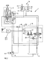
- Fig. 2 shows a device 1 for regulating the two hydraulic cylinders 2, 3 of the wheel loader 100.
- the lines marked by solid lines indicate main lines, and the lines marked by dashed lines indicate pilot lines for regulating various components in the system.
- the system comprises a first control valve 4 which is regulated mechanically by the steering wheel of the vehicle.
- the system also comprises a second control valve 6 which is controlled electronically via a control element 7 in the form of a lever or a joystick. Control via the lever 7 is shown diagrammatically by dotted lines.
- the system is load-sensing (LS) and comprises a variable displacement pump 8 and a tank 9.
- the pump 8 is driven by the propulsion engine 44 of the vehicle, in the form of a diesel engine.
- the pump 8 senses the pressure (an LS signal) from the steering cylinders 2, 3 via a shuttle valve 10 and via the control valve 4, 6 which is activated.
- the pump then sets a pressure which is a certain number of bar higher than the pressure of the steering cylinders. This brings about an oil flow out to the steering cylinders 2, 3, the level of which depends on the extent to which the activated control valve 4, 6 is operated.
- the hydraulic cylinders 2, 3 are adapted in such a way that the piston side 11 of the first hydraulic cylinder 2 and the piston-rod side 12 of the second hydraulic cylinder 3 are connected to the pump 8 for steering the vehicle to the right, and the piston-rod side 13 of the first hydraulic cylinder 2 and the piston side 14 of the second hydraulic cylinder 3 are connected to the pump for steering the vehicle to the left.
- connection of the hydraulic cylinders 2, 3 to the pump 8 and thus the regulation of the hydraulic cylinders can be carried out either via steering-wheel steering by means of the control valve 4 or via lever steering by means of the control valve 6.
- the second control valve 6 comprises a directional valve 18 which determines the steering direction and also the control flow, and a pressure-reducing valve 19 which ensures that the pilot pressure is limited to a defined level, irrespective of the pump pressure.
- the control valve 6 also comprises two electrically controlled valves 20, 21 which are regulated indirectly via an electric signal from the lever 7.
- the electrically controlled valves 20, 21 are arranged in parallel with one another on a line 28.
- the line 28 is also connected to the directional valve 18 on both its sides for movement thereof counter to spring force.
- the pump 8 is connected to the electric valves 20, 21 via a line 29 which is connected to the line 28 between the electric valves.
- the electrically controlled right-hand valve 21 is therefore activated, which then applies an oil pressure, which is proportional to the electric signal, to the directional valve 18.
- an oil pressure which is proportional to the electric signal
- the electrically controlled left-hand valve 20 is therefore activated in a corresponding way.
- the LS signal is connected from the shuttle valve 10 (see line 50) to the tank 9 via the directional valve 18 and is thus in principle pressureless.
- the pump 8 is thus adjusted down and maintains only a low pressure.
- the two electrically controlled valves 20, 21 are therefore arranged in such a way that activation of one valve results in movement of the directional valve 18 in one direction, and activation of the other valve results in movement of the directional valve 18 in the other direction.
- the system comprises a top-up valve and a choke valve, which are indicated together by reference number 5.
- the function of the top-up valve and the choke valve is previously known and will therefore not be described in detail here.
- the device 1 also comprises a control unit 15 connected to the lever 7.
- the control unit 15 may also be called, for example, a computer unit or CPU (Control Power Unit).
- the control valve 6 is regulated by an electric signal.
- the control unit 15 is therefore connected to the hydraulic cylinders 2, 3 via the control valve 6.
- the device also comprises a system 17 for sensing the speed of the vehicle.
- the sensing system comprises, for example, one or more sensors for sensing the speed of rotation of a rotating part in the transmission of the vehicle. This is known per se and will not be described in greater detail here.
- This sensing system 17 is connected to the control unit 15.
- the control unit 15 is adapted to define the steering angle speed as a function of the sensed vehicle speed.
- the signal of the lever 7 can therefore be manipulated in the control unit 15.
- the control unit 15 has the machine speed and the lever position as input signals and can, for example, define extreme values for the steering deflection and ramps in order to achieve the steering deflection.
- the size of the ramps is a function of the machine speed.
- the deflection limit that is to say a maximum permitted steering deflection, can also be a function of the machine speed.
- the steering angle value is therefore defined in time order after the sensing of the movement of the control lever.
- Figure 3 shows two curves, or ramps, A, B for regulating the steering angle speed as a function of time.
- Ramp A is used for low vehicle speed, and ramp B for high vehicle speed.
- Ramp A has a large amplification (high final steering angle speed) and a long ramp time. This means that a certain lever deflection gives a relatively great steering deflection which feels relatively gentle for the driver.
- Ramp B has a low amplification (low final steering angle speed) and a short ramp time. This means that said lever deflection gives a steering deflection which corresponds to the lever movement and that it takes place quickly, that is to say a short delay.
- Ramps A and B are linear, that is to say the steering angle speed is increased proportionally with increased time to a maximum value.
- Figure 4 shows various examples of characteristics of ramps for changing the steering angle speed, namely step-shaped C, degressive D, linear E and progressive F.
- the rise time can be changed proportionally to the vehicle speed, for example.
- a step-shaped ramp at high speeds use is made of a step-shaped ramp at high speeds and a linear ramp at low speeds.
- the computer unit of the vehicle comprises a memory which in turn comprises a computer program product with computer program segments, or a program code, for performing all the steps according to the control method when the program is run.
- the computer program product can be the actual software for carrying out the method, or hardware on which the software is stored, that is to say a disk or the like.
- the speed of the vehicle means speed in the longitudinal direction of the vehicle, that is to say both forward and backward.
- control apparatuses which do not have a linear movement pattern, such as an angular control apparatus (for example a steering wheel or crank) with sensors, or electric transducers, which function in a similar way to the lever described.
- angular control apparatus for example a steering wheel or crank
- sensors for example a steering wheel or crank
- electric transducers which function in a similar way to the lever described.
- Figure 5 illustrates diagrammatically such an embodiment where the control element consists of a steering wheel 107.
- the movements of the steering wheel 107 are detected by one or more sensor(s) 200 connected to a control unit 115.
- a system 117 for sensing the speed of the vehicle is also connected to the control unit 115.
- a second control valve 106 is controlled electronically from the control unit 115.
- the second control valve 106 in turn regulates in the way described above turning means 116 in the form of the two hydraulic steering cylinders 2, 3 which are arranged between the two vehicle parts.
- the sensors 200 measure angular positions
- the control unit 115 comprises a time counter by means of which the control unit can convert the angular positions measured into a steering wheel speed.
- the steering wheel speed is sensed directly, for example via a pulse meter connected to the control unit 115.
- the steering angle speed that is to say the speed at which the steering angle of the vehicle is changed, is then controlled depending on the steering wheel speed.
- a certain steering wheel speed can therefore correspond to a certain speed of change of steering angle within a certain vehicle speed range.
- the same steering wheel speed can then correspond to a lower speed of change of steering angle within a second, higher vehicle speed range.
- the ramps according to Figures 3 and 4 it is possible, for example, for the ramps according to Figures 3 and 4 to be used in order to achieve different changes of steering angle speed.
- the invention is not to be regarded as being limited to the illustrative embodiments described above, but a number of further variants and modifications are conceivable within the scope of the following patent claims.
- the invention can also, for example, be applied to vehicles other than wheel loaders, such as an articulated or frame-steered vehicle, also known as a dumper.
Landscapes
- Engineering & Computer Science (AREA)
- Chemical & Material Sciences (AREA)
- Combustion & Propulsion (AREA)
- Transportation (AREA)
- Mechanical Engineering (AREA)
- Operation Control Of Excavators (AREA)
- Steering Control In Accordance With Driving Conditions (AREA)
- Power Steering Mechanism (AREA)
- Forklifts And Lifting Vehicles (AREA)
- Steering Controls (AREA)
- Control Of Position, Course, Altitude, Or Attitude Of Moving Bodies (AREA)
Abstract
Description
- The present invention relates to a method for controlling a vehicle according to the preamble of claim 1. The invention also relates to a device for controlling a vehicle according to the preamble of
claim 14 which is described inUS-A-6173221 . - The present invention relates primarily to a working machine in the form of a wheel loader. The wheel loader comprises a front and a rear body part, which parts are interconnected in an articulated manner and each have a drive axle. The body parts are rotatable relative to one another around an articulation via two hydraulic cylinders arranged between the two parts. Below, "steering angle" means the mutual adjustment of the two drive axles. The hydraulic cylinders are therefore arranged for steering, that is to say turning, the wheel loader. ,
- A wheel loader usually has normal steering-wheel steering but may in parallel be equipped with lever steering. Using the steering-wheel steering, the driver regulates mechanically a first hydraulic valve which in turn transmits hydraulic energy to the hydraulic cylinders. When lever steering is used, hydraulic energy is instead transmitted to the hydraulic cylinders via a second hydraulic valve, but this second hydraulic valve is controlled by electric signals, that is to say, when the lever is moved, an electric signal is generated, which controls the second hydraulic valve.
- When lever steering is used, the speed of change of the steering angle is controlled by the position of the lever. A large lever deflection gives a rapid change of steering angle, and a small lever deflection gives a slow change of steering angle. When the lever is guided back into the neutral position after a deflection, the steering angle brought about is maintained.
- The steering wheel is usually used for transport, and the lever is usually used for work at lower speeds such as, for example, loading a truck, in order to increase driver comfort. In some applications, however, the driver may prefer to use the lever for transport as well. Transport and loading are two different handling operations of the wheel loader which place very different demands on the vehicle. During a loader cycle, the wheel loader is driven forward and backward for short distances and is turned in the meantime in order to load and unload the bucket.
- A first object of the invention is to provide a method for controlling a vehicle which remedies problems associated with controlling the vehicle in different applications.
- This object is achieved by a method according to the characterizing part of claim 1.
- According to a preferred embodiment of the invention, the steering angle speed is changed with time for at least a first predetermined speed range. In other words, use is made of what is known as a ramp. The ramp may be of a number of different types, for example linear, progressive, degressive or step-shaped. According to a preferred example, the change of the steering angle speed is increased proportionally with time over said first speed range.
- According to another preferred embodiment of the invention, the steering angle speed is changed directly corresponding to the movement of the control element for at least a second predetermined speed range. The expression direct control means a method which may correspond to mechanical-hydraulic transmission without electric control. In other words, the signal from the lever is not manipulated in connection with changing the steering angle speed. On the other hand, the amplitude of the signal can be amplified or attenuated. The first predetermined speed range is preferably lower than the second predetermined speed range.
- This first speed range is preferably a lower speed range, corresponding to loading mode, for example from 0 km/h to 10 km/h, and the second speed range is preferably a higher speed range, corresponding to transport mode, for example from 10 km/h upward.
- A second object of the invention is to produce a device for controlling a vehicle which remedies problems associated with controlling the vehicle in different applications.
- This is achieved by a device according to the characterizing part of
claim 14. - Further preferred embodiments and advantages of the invention emerge from the other dependent claims and also from the description below.
- The invention will be described in greater detail below, with reference to the embodiment shown in the accompanying drawings, in which
- FIG. 1
- shows a diagrammatic view from above of a wheel loader;
- FIG. 2
- shows a device for controlling a vehicle;
- FIGS 3 and 4
- show graphs of different examples of ramps for steering angle speed regulation, and
- FIG. 5
- shows diagrammatically an alternative device for controlling the vehicle.
- Fig. 1 shows a diagrammatic view from above of a heavy-duty vehicle in the form of a
wheel loader 100. Thewheel loader 100 comprises a front and arear part wheel axle vehicle parts articulation 105 via means 16 for turning the vehicle. - Said turning means 16 comprise two
hydraulic cylinders - Fig. 2 shows a device 1 for regulating the two
hydraulic cylinders wheel loader 100. The lines marked by solid lines indicate main lines, and the lines marked by dashed lines indicate pilot lines for regulating various components in the system. - The system comprises a first control valve 4 which is regulated mechanically by the steering wheel of the vehicle. The system also comprises a second control valve 6 which is controlled electronically via a
control element 7 in the form of a lever or a joystick. Control via thelever 7 is shown diagrammatically by dotted lines. - The system is load-sensing (LS) and comprises a
variable displacement pump 8 and atank 9. Thepump 8 is driven by thepropulsion engine 44 of the vehicle, in the form of a diesel engine. Thepump 8 senses the pressure (an LS signal) from thesteering cylinders shuttle valve 10 and via the control valve 4, 6 which is activated. The pump then sets a pressure which is a certain number of bar higher than the pressure of the steering cylinders. This brings about an oil flow out to thesteering cylinders - The
hydraulic cylinders piston side 11 of the firsthydraulic cylinder 2 and the piston-rod side 12 of the secondhydraulic cylinder 3 are connected to thepump 8 for steering the vehicle to the right, and the piston-rod side 13 of the firsthydraulic cylinder 2 and thepiston side 14 of the secondhydraulic cylinder 3 are connected to the pump for steering the vehicle to the left. - The connection of the
hydraulic cylinders pump 8 and thus the regulation of the hydraulic cylinders can be carried out either via steering-wheel steering by means of the control valve 4 or via lever steering by means of the control valve 6. - The design and function of the first control valve 4 are previously known and are therefore not described in detail here.
- The second control valve 6 comprises a
directional valve 18 which determines the steering direction and also the control flow, and a pressure-reducingvalve 19 which ensures that the pilot pressure is limited to a defined level, irrespective of the pump pressure. The control valve 6 also comprises two electrically controlledvalves lever 7. The electrically controlledvalves directional valve 18 on both its sides for movement thereof counter to spring force. Thepump 8 is connected to theelectric valves line 29 which is connected to the line 28 between the electric valves. The result of this is that activation of the right-hand valve 21, via thelever 7, produces an oil pressure on thedirectional valve 18 for movement of the latter to the right in the figure counter to a spring force, and activation of the left-hand valve 20, via thelever 7, produces an oil pressure on thedirectional valve 18 for movement of the latter to the left in the figure counter to a spring force. - For steering to the right, the electrically controlled right-
hand valve 21 is therefore activated, which then applies an oil pressure, which is proportional to the electric signal, to thedirectional valve 18. The higher the electric signal (oil pressure), the more thedirectional valve 18 is operated, and a greater control flow is thus obtained. For steering to the left, the electrically controlled left-hand valve 20 is therefore activated in a corresponding way. - When the control valve 6 is not activated, the LS signal is connected from the shuttle valve 10 (see line 50) to the
tank 9 via thedirectional valve 18 and is thus in principle pressureless. The same applies for the first control valve 4, which also connects the LS signal to thetank 9 when it is not activated. Thepump 8 is thus adjusted down and maintains only a low pressure. The two electrically controlledvalves directional valve 18 in one direction, and activation of the other valve results in movement of thedirectional valve 18 in the other direction. - In order to prevent negative pressures and pressures exceeding a defined maximum pressure in the system, the system comprises a top-up valve and a choke valve, which are indicated together by reference number 5. The function of the top-up valve and the choke valve is previously known and will therefore not be described in detail here.
- The device 1 also comprises a
control unit 15 connected to thelever 7. Thecontrol unit 15 may also be called, for example, a computer unit or CPU (Control Power Unit). By means of thecontrol unit 15, the control valve 6 is regulated by an electric signal. Thecontrol unit 15 is therefore connected to thehydraulic cylinders - The device also comprises a
system 17 for sensing the speed of the vehicle. The sensing system comprises, for example, one or more sensors for sensing the speed of rotation of a rotating part in the transmission of the vehicle. This is known per se and will not be described in greater detail here. Thissensing system 17 is connected to thecontrol unit 15. - The
control unit 15 is adapted to define the steering angle speed as a function of the sensed vehicle speed. The signal of thelever 7 can therefore be manipulated in thecontrol unit 15. Thecontrol unit 15 has the machine speed and the lever position as input signals and can, for example, define extreme values for the steering deflection and ramps in order to achieve the steering deflection. According to a preferred embodiment, the size of the ramps is a function of the machine speed. If appropriate, the deflection limit, that is to say a maximum permitted steering deflection, can also be a function of the machine speed. - The steering angle value is therefore defined in time order after the sensing of the movement of the control lever.
- Figure 3 shows two curves, or ramps, A, B for regulating the steering angle speed as a function of time. Ramp A is used for low vehicle speed, and ramp B for high vehicle speed. Ramp A has a large amplification (high final steering angle speed) and a long ramp time. This means that a certain lever deflection gives a relatively great steering deflection which feels relatively gentle for the driver. Ramp B has a low amplification (low final steering angle speed) and a short ramp time. This means that said lever deflection gives a steering deflection which corresponds to the lever movement and that it takes place quickly, that is to say a short delay. Ramps A and B are linear, that is to say the steering angle speed is increased proportionally with increased time to a maximum value.
- Figure 4 shows various examples of characteristics of ramps for changing the steering angle speed, namely step-shaped C, degressive D, linear E and progressive F. The rise time can be changed proportionally to the vehicle speed, for example.
- According to a preferred example, use is made of a step-shaped ramp at high speeds and a linear ramp at low speeds.
- The computer unit of the vehicle comprises a memory which in turn comprises a computer program product with computer program segments, or a program code, for performing all the steps according to the control method when the program is run. The computer program product can be the actual software for carrying out the method, or hardware on which the software is stored, that is to say a disk or the like.
- The speed of the vehicle means speed in the longitudinal direction of the vehicle, that is to say both forward and backward.
- The above can also be applied to control apparatuses which do not have a linear movement pattern, such as an angular control apparatus (for example a steering wheel or crank) with sensors, or electric transducers, which function in a similar way to the lever described.
- Figure 5 illustrates diagrammatically such an embodiment where the control element consists of a
steering wheel 107. The movements of thesteering wheel 107 are detected by one or more sensor(s) 200 connected to acontrol unit 115. Asystem 117 for sensing the speed of the vehicle is also connected to thecontrol unit 115. Asecond control valve 106 is controlled electronically from thecontrol unit 115. Thesecond control valve 106 in turn regulates in the way described above turning means 116 in the form of the twohydraulic steering cylinders - According to a first alternative, the
sensors 200 measure angular positions, and thecontrol unit 115 comprises a time counter by means of which the control unit can convert the angular positions measured into a steering wheel speed. According to a second alternative, the steering wheel speed is sensed directly, for example via a pulse meter connected to thecontrol unit 115. The steering angle speed, that is to say the speed at which the steering angle of the vehicle is changed, is then controlled depending on the steering wheel speed. - It is therefore possible to apply the examples described above for lever steering for steering-wheel steering as well. A certain steering wheel speed can therefore correspond to a certain speed of change of steering angle within a certain vehicle speed range. The same steering wheel speed can then correspond to a lower speed of change of steering angle within a second, higher vehicle speed range. In a corresponding way, it is possible, for example, for the ramps according to Figures 3 and 4 to be used in order to achieve different changes of steering angle speed.
- The embodiment for electronic lever steering according to Figure 2 can of course be combined with the embodiment for electronic steering-wheel steering according to Figure 5.
- The invention is not to be regarded as being limited to the illustrative embodiments described above, but a number of further variants and modifications are conceivable within the scope of the following patent claims. The invention can also, for example, be applied to vehicles other than wheel loaders, such as an articulated or frame-steered vehicle, also known as a dumper.
Claims (29)
- A method for controlling a vehicle (100), operation of a control element (7, 107) by the driver of the vehicle being sensed, and the steering angle of the vehicle being regulated depending on the operation of the control element, wherein the speed of the vehicle is sensed, a procedure for changing the steering angle of the vehicle is defined based on the sensed operation of the control element and the sensed vehicle speed, and the steering angle of the vehicle is regulated according to the defined procedure characterized in that the speed of change of the steering angle is defined as a function of the sensed vehicle speed, that the speed of change of the steering angle is defined in an inverse relationship relative to the sensed vehicle speed, that the procedure comprises a ramp (A, B, C, D, E) at its start in order to reach a defined speed of change of the steering angle and that the ramp (A, B, C, D, E) is shorter in terms of time for a sensed vehicle speed within a higher vehicle speed range than within a lower vehicle speed range.
- The method as claimed in claim 1, characterized in that the position of the control element (7) is sensed, and in that the procedure for changing the steering angle of the vehicle is defined directly based on the sensed position of the control element (7).
- The method as claimed in claim 1, characterized in that the speed with which the control element (107) is regulated is determined, and in that the procedure for changing the steering angle of the vehicle is defined based on the determined speed of the control element (107).
- The method as claimed in any one of the preceding claims, characterized in that the slope of the ramp (A, B, C, D, E) is different for at least two different vehicle speed ranges.
- The method as claimed in any one of the preceding claims, characterized in that the steering angle speed is changed with time for at least a first predetermined speed range.
- The method as claimed in claim 5, characterized in that the change of the steering angle speed is increased proportionally with time over said first speed range.
- The method as claimed in any one of the preceding claims, characterized in that the steering angle speed is changed directly corresponding to the movement of the control element for at least a second predetermined speed range.
- The method as claimed in claim 5 or 6, and claim 7, characterized in that the first predetermined speed range is lower than the second predetermined speed range.
- The method as claimed in any one of the preceding claims, characterized in that, to bring about regulation of the steering angle of the vehicle, the position of a directional valve (18) is regulated, which directional valve is adapted for regulating the supply of a fluid from a pump (8) to means (16, 116, 2, 3) for turning the vehicle.
- The method as claimed in any one of the preceding claims, characterized in that the steering angle of the vehicle is regulated via a system of at least one hydraulic cylinder (2, 3).
- The method as claimed in claim 10, characterized in that said hydraulic cylinder system is arranged between a front and a rear body part (101, 102) of the vehicle, which body parts each comprise at least one wheel axle (103, 104) and are arranged rotatably relative to one another.
- The method as claimed in any one of the preceding claims, characterized in that the vehicle consists of a working machine.
- The method as claimed in any one of the preceding claims, characterized in that the vehicle consists of a wheel loader.
- A device for controlling a vehicle (100) comprising a control element (7, 107) for operation by the driver of the vehicle, means (16, 116, 2, 3) for turning the vehicle and a control unit (15, 115) connected to the control element and said turning means for regulating the steering angle of the vehicle depending on the operation of the control element, wherein the device comprises a system (17, 117) for sensing the speed of the vehicle, the control unit (15, 115) is connected to the sensing system, and the control unit is adapted to define a procedure for changing the steering angle of the vehicle based on the sensed operation of the control element and the sensed vehicle speed and to cause said turning means (16, 116, 2, 3) to regulate the steering angle of the vehicle according to the defined procedure, characterized in that the control unit (15) is adapted to define the speed of change of the steering angle as a function of the sensed vehicle speed, that the control unit (15) is adapted to define the speed of change of the steering angle in an inverse relationship relative to the sensed vehicle speed, that the control unit (15, 115) is adapted to use a ramp (A, B, C, D, E) at the start of the procedure in order to reach a defined speed of change of the steering angle, and that the ramp (A, B, C, D, E) is shorter in terms of time for a sensed vehicle speed within a higher vehicle speed range than within a lower vehicle speed range.
- The control device as claimed in claim 14, characterized in that the device comprises a sensor for sensing the position of the control element (7), and in that the control unit (15) is adapted to define the procedure for changing the steering angle of the vehicle directly based on the sensed position of the control element (7).
- The control device as claimed in claim 14 or 15, characterized in that the device comprises means for determining the speed with which the control element (107) is regulated, and in that the control unit (115) is adapted to define the procedure for changing the steering angle of the vehicle based on the determined speed of the control element (107).
- The control device as claimed in any one of claims 14-16, characterized in that the ramp (A, B, C, D, E) is of different length in terms of time for different vehicle speed ranges.
- The control device as claimed in any one of claims 14-17, characterized in that the control unit (15) is adapted to change the steering angle speed with time for at least a first predetermined speed range.
- The control device as claimed in claim 18, characterized in that the control unit (15) is adapted to increase the change of the steering angle speed proportionally with time over said first speed range.
- The control device as claimed in any one of claims 14-19, characterized in that the control unit (15) is adapted to change the steering angle speed directly corresponding to the movement of the control element for at least a second predetermined speed range.
- The control device as claimed in claim 18 or 19, and 20, characterized in that the first predetermined speed range is lower than the second predetermined speed range.
- The control device as claimed in any one of claims 14-21, characterized in that the control device comprises a directional valve (18) which is adapted for regulating the supply of a fluid from a pump (8) to said turning means (16, 116, 2, 3), and in that the control unit (15) is connected to the directional valve for regulating its position for the purpose of regulating the steering angle of the vehicle.
- The control device as claimed in any one of claims 14-22, characterized in that said turning means (16, 116) comprise a system of at least one hydraulic cylinder (2, 3) for changing the steering angle.
- The control device as claimed in claim 23, characterized in that said hydraulic cylinder system (2, 3) is arranged between a front and a rear body part (101, 102) of the vehicle, which body parts each comprise at least one wheel axle (103, 104) and are arranged rotatably relative to one another.
- The control device as claimed in any one of claims 14-24, characterized in that the control element (7) consists of a control lever.
- The control device as claimed in any one of claims 14-25, characterized in that the control element (7) consists of an element intended for rotation, such as a steering wheel.
- A working machine, characterized in that it comprises a control device as claimed in any one of claims 14-26.
- A wheel loader, characterized in that it comprises a control device as claimed in any one of claims 14-26.
- A computer program product comprising computer program segments for causing the control unit of the vehicle to perform the steps as claimed in any one of claims 1-13.
Applications Claiming Priority (3)
| Application Number | Priority Date | Filing Date | Title |
|---|---|---|---|
| SE0202739A SE525774C2 (en) | 2002-09-13 | 2002-09-13 | Procedure, device and computer software product for controlling a vehicle |
| SE0202739 | 2002-09-13 | ||
| PCT/SE2003/001206 WO2004024537A1 (en) | 2002-09-13 | 2003-07-11 | A method, device and computer program product for controlling the steering of a vehicle |
Publications (2)
| Publication Number | Publication Date |
|---|---|
| EP1539560A1 EP1539560A1 (en) | 2005-06-15 |
| EP1539560B1 true EP1539560B1 (en) | 2007-09-19 |
Family
ID=20289000
Family Applications (1)
| Application Number | Title | Priority Date | Filing Date |
|---|---|---|---|
| EP03738859A Expired - Lifetime EP1539560B1 (en) | 2002-09-13 | 2003-07-11 | A method, device and computer program product for controlling the steering of a vehicle |
Country Status (8)
| Country | Link |
|---|---|
| EP (1) | EP1539560B1 (en) |
| JP (1) | JP4445861B2 (en) |
| CN (1) | CN100379630C (en) |
| AT (1) | ATE373596T1 (en) |
| AU (1) | AU2003246231A1 (en) |
| DE (1) | DE60316455T2 (en) |
| SE (1) | SE525774C2 (en) |
| WO (1) | WO2004024537A1 (en) |
Cited By (1)
| Publication number | Priority date | Publication date | Assignee | Title |
|---|---|---|---|---|
| US12024861B2 (en) | 2018-08-13 | 2024-07-02 | Komatsu Ltd. | Work vehicle |
Families Citing this family (20)
| Publication number | Priority date | Publication date | Assignee | Title |
|---|---|---|---|---|
| SE529526C2 (en) * | 2006-01-16 | 2007-09-04 | Volvo Constr Equip Ab | Vehicle control system for use in frame steered vehicle, has steering cylinders, drive units with electrical and hydraulic machine for flow communication |
| US7721842B2 (en) * | 2006-09-01 | 2010-05-25 | Deere & Company | Articulated work vehicle steering system with controlled steering cushioning and associated method |
| JP2008120116A (en) * | 2006-11-08 | 2008-05-29 | Hitachi Constr Mach Co Ltd | Bending construction vehicle |
| KR101317602B1 (en) | 2006-12-06 | 2013-10-11 | 두산인프라코어 주식회사 | Steering control device of electric-joystick of wheel loader |
| JP4805118B2 (en) * | 2006-12-13 | 2011-11-02 | 日立建機株式会社 | Power steering device |
| JP5052147B2 (en) * | 2007-01-25 | 2012-10-17 | 日立建機株式会社 | Steering device for construction vehicles |
| WO2009113917A1 (en) * | 2008-03-11 | 2009-09-17 | Volvo Construction Equipment Ab | Control system and working machine comprising the control system |
| KR101530715B1 (en) * | 2008-12-19 | 2015-06-22 | 두산인프라코어 주식회사 | Steering device of wheel loader with emergency steering/electric steering pump |
| US8056672B2 (en) * | 2009-12-09 | 2011-11-15 | Deere & Company | Steering control system combining electro-hydraulic and manually-actuated pilot pressure control valves for safe operation |
| DE102011013248B4 (en) * | 2011-03-07 | 2021-02-11 | Jungheinrich Aktiengesellschaft | Method and device for controlling or regulating the operation of an industrial truck |
| CN102285374A (en) * | 2011-06-01 | 2011-12-21 | 金龙联合汽车工业(苏州)有限公司 | Electric hydraulic steering system used for passenger car |
| JP6135317B2 (en) * | 2013-06-13 | 2017-05-31 | スズキ株式会社 | Vehicle steering angle estimation device |
| JP6433750B2 (en) * | 2014-10-16 | 2018-12-05 | 株式会社Kcm | Steering control device for work vehicle |
| EP3178724B1 (en) * | 2015-12-08 | 2018-10-24 | Volvo Car Corporation | Vehicle steering arrangement, autonomous vehicle steering arrangement, a vehicle, and a method of steering a vehicle |
| US10040476B2 (en) * | 2016-11-02 | 2018-08-07 | Caterpillar Inc. | Autonomous steering system for an articulated truck |
| JP7154814B2 (en) * | 2018-04-26 | 2022-10-18 | 株式会社小松製作所 | Working machine and its control method |
| CN108909832B (en) * | 2018-08-15 | 2021-11-09 | 广西柳工机械股份有限公司 | Steering hydraulic system and loader |
| US11667326B2 (en) * | 2019-09-18 | 2023-06-06 | Deere & Company | Automatic guidance performance improvement and transport with articulated machine form |
| CN113147896B (en) * | 2021-03-16 | 2022-08-09 | 江苏汇智高端工程机械创新中心有限公司 | Articulated steering distributed electric drive steering control method and system and loader |
| CN119099725B (en) * | 2024-10-16 | 2025-10-17 | 华南农业大学 | Nonlinear vibration reduction hinge steering structure |
Family Cites Families (5)
| Publication number | Priority date | Publication date | Assignee | Title |
|---|---|---|---|---|
| US4003202A (en) * | 1976-03-11 | 1977-01-18 | General Signal Corporation | Variable feedback steering system |
| US5181173A (en) * | 1991-07-23 | 1993-01-19 | Raymond Corporation | Variable ratio steering system for a motor vehicle |
| SE9404119L (en) * | 1994-11-28 | 1996-05-29 | Bt Ind Ab | Variable steering for trucks |
| DE19645646C1 (en) * | 1996-11-06 | 1998-02-12 | Daimler Benz Ag | Steering angle control device e.g. for automobile |
| SE9804467L (en) * | 1998-12-21 | 2000-06-22 | Volvo Ab | Device for a control system and method of controlling a motor vehicle via said control system |
-
2002
- 2002-09-13 SE SE0202739A patent/SE525774C2/en not_active IP Right Cessation
-
2003
- 2003-07-11 WO PCT/SE2003/001206 patent/WO2004024537A1/en not_active Ceased
- 2003-07-11 DE DE60316455T patent/DE60316455T2/en not_active Expired - Lifetime
- 2003-07-11 EP EP03738859A patent/EP1539560B1/en not_active Expired - Lifetime
- 2003-07-11 AU AU2003246231A patent/AU2003246231A1/en not_active Abandoned
- 2003-07-11 JP JP2004535313A patent/JP4445861B2/en not_active Expired - Fee Related
- 2003-07-11 AT AT03738859T patent/ATE373596T1/en not_active IP Right Cessation
- 2003-07-11 CN CNB038216701A patent/CN100379630C/en not_active Expired - Lifetime
Cited By (1)
| Publication number | Priority date | Publication date | Assignee | Title |
|---|---|---|---|---|
| US12024861B2 (en) | 2018-08-13 | 2024-07-02 | Komatsu Ltd. | Work vehicle |
Also Published As
| Publication number | Publication date |
|---|---|
| EP1539560A1 (en) | 2005-06-15 |
| SE0202739D0 (en) | 2002-09-13 |
| WO2004024537A1 (en) | 2004-03-25 |
| DE60316455D1 (en) | 2007-10-31 |
| SE525774C2 (en) | 2005-04-26 |
| ATE373596T1 (en) | 2007-10-15 |
| CN100379630C (en) | 2008-04-09 |
| SE0202739L (en) | 2004-03-14 |
| AU2003246231A1 (en) | 2004-04-30 |
| JP2005538883A (en) | 2005-12-22 |
| DE60316455T2 (en) | 2008-06-26 |
| JP4445861B2 (en) | 2010-04-07 |
| CN1688473A (en) | 2005-10-26 |
Similar Documents
| Publication | Publication Date | Title |
|---|---|---|
| US7407034B2 (en) | Method, device and computer program product for controlling the steering of a vehicle | |
| EP1539560A1 (en) | A method, device and computer program product for controlling the steering of a vehicle | |
| US6176083B1 (en) | Apparatus and method for controlling displacement of steering pump for work vehicle | |
| US5720358A (en) | Apparatus for controlling the torque on a power train and method of operating the same | |
| JP5631882B2 (en) | Hydraulic steering system including first and second steering members, and vehicle including hydraulic steering system | |
| US20090319133A1 (en) | method for controlling a movement of a vehicle component | |
| US5975224A (en) | Method for controlling steering in a hydrostatic drive system having differential steer | |
| CN104918842A (en) | System with smart steering force feedback | |
| JP2008074393A (en) | Articulated work vehicle steering system with controlled steering cushioning and associated method | |
| US8196400B2 (en) | Method and an arrangement for controlling pump displacement in a work vehicle | |
| US7225894B2 (en) | Power steering apparatus | |
| US5857532A (en) | Differential steer system for a machine | |
| US5865512A (en) | Method and apparatus for modifying the feedback gains of a traction control system | |
| US12529206B2 (en) | Work machine and method for controlling work machine | |
| JPS6121862A (en) | Power steering gear for car | |
| EP3705380B1 (en) | Work vehicle | |
| US20110272204A1 (en) | Hydraulic Power-Assisted Steering and Method for Determining Steering Wheel Torque | |
| US7891459B2 (en) | Multiple ratio steering for loader | |
| US20250100615A1 (en) | A Steering System and a Method of Controlling a Steering System | |
| WO2018081371A1 (en) | Apparatus and method for turning steerable vehicle wheels | |
| EP0665157A1 (en) | Power-steering device for motor-vehicles | |
| EP4526182A1 (en) | A steering system and a method of controlling a steering system | |
| EP3719356B1 (en) | Hydrostatic transmission for a work vehicle provided with a system for reducing the jerk during direction inversion manoeuvres | |
| JP3266348B2 (en) | Hydraulic motor drive circuit for work vehicle traveling | |
| GB2332407A (en) | Method of providing quick steering changes in a vehicle having both steerable and differentially-driven wheels |
Legal Events
| Date | Code | Title | Description |
|---|---|---|---|
| PUAI | Public reference made under article 153(3) epc to a published international application that has entered the european phase |
Free format text: ORIGINAL CODE: 0009012 |
|
| 17P | Request for examination filed |
Effective date: 20050413 |
|
| AK | Designated contracting states |
Kind code of ref document: A1 Designated state(s): AT BE BG CH CY CZ DE DK EE ES FI FR GB GR HU IE IT LI LU MC NL PT RO SE SI SK TR |
|
| AX | Request for extension of the european patent |
Extension state: AL LT LV MK |
|
| DAX | Request for extension of the european patent (deleted) | ||
| GRAP | Despatch of communication of intention to grant a patent |
Free format text: ORIGINAL CODE: EPIDOSNIGR1 |
|
| GRAS | Grant fee paid |
Free format text: ORIGINAL CODE: EPIDOSNIGR3 |
|
| GRAA | (expected) grant |
Free format text: ORIGINAL CODE: 0009210 |
|
| AK | Designated contracting states |
Kind code of ref document: B1 Designated state(s): AT BE BG CH CY CZ DE DK EE ES FI FR GB GR HU IE IT LI LU MC NL PT RO SE SI SK TR |
|
| REG | Reference to a national code |
Ref country code: GB Ref legal event code: FG4D |
|
| REG | Reference to a national code |
Ref country code: CH Ref legal event code: EP |
|
| REF | Corresponds to: |
Ref document number: 60316455 Country of ref document: DE Date of ref document: 20071031 Kind code of ref document: P |
|
| REG | Reference to a national code |
Ref country code: DE Ref legal event code: R096 Ref document number: 60316455 Country of ref document: DE Effective date: 20071031 |
|
| REG | Reference to a national code |
Ref country code: IE Ref legal event code: FG4D |
|
| PG25 | Lapsed in a contracting state [announced via postgrant information from national office to epo] |
Ref country code: FI Free format text: LAPSE BECAUSE OF FAILURE TO SUBMIT A TRANSLATION OF THE DESCRIPTION OR TO PAY THE FEE WITHIN THE PRESCRIBED TIME-LIMIT Effective date: 20070919 |
|
| PG25 | Lapsed in a contracting state [announced via postgrant information from national office to epo] |
Ref country code: AT Free format text: LAPSE BECAUSE OF FAILURE TO SUBMIT A TRANSLATION OF THE DESCRIPTION OR TO PAY THE FEE WITHIN THE PRESCRIBED TIME-LIMIT Effective date: 20070919 Ref country code: CH Free format text: LAPSE BECAUSE OF FAILURE TO SUBMIT A TRANSLATION OF THE DESCRIPTION OR TO PAY THE FEE WITHIN THE PRESCRIBED TIME-LIMIT Effective date: 20070919 Ref country code: LI Free format text: LAPSE BECAUSE OF FAILURE TO SUBMIT A TRANSLATION OF THE DESCRIPTION OR TO PAY THE FEE WITHIN THE PRESCRIBED TIME-LIMIT Effective date: 20070919 |
|
| NLV1 | Nl: lapsed or annulled due to failure to fulfill the requirements of art. 29p and 29m of the patents act | ||
| REG | Reference to a national code |
Ref country code: CH Ref legal event code: PL |
|
| PG25 | Lapsed in a contracting state [announced via postgrant information from national office to epo] |
Ref country code: ES Free format text: LAPSE BECAUSE OF FAILURE TO SUBMIT A TRANSLATION OF THE DESCRIPTION OR TO PAY THE FEE WITHIN THE PRESCRIBED TIME-LIMIT Effective date: 20071230 Ref country code: NL Free format text: LAPSE BECAUSE OF FAILURE TO SUBMIT A TRANSLATION OF THE DESCRIPTION OR TO PAY THE FEE WITHIN THE PRESCRIBED TIME-LIMIT Effective date: 20070919 Ref country code: GR Free format text: LAPSE BECAUSE OF FAILURE TO SUBMIT A TRANSLATION OF THE DESCRIPTION OR TO PAY THE FEE WITHIN THE PRESCRIBED TIME-LIMIT Effective date: 20071220 |
|
| EN | Fr: translation not filed | ||
| PG25 | Lapsed in a contracting state [announced via postgrant information from national office to epo] |
Ref country code: CZ Free format text: LAPSE BECAUSE OF FAILURE TO SUBMIT A TRANSLATION OF THE DESCRIPTION OR TO PAY THE FEE WITHIN THE PRESCRIBED TIME-LIMIT Effective date: 20070919 Ref country code: PT Free format text: LAPSE BECAUSE OF FAILURE TO SUBMIT A TRANSLATION OF THE DESCRIPTION OR TO PAY THE FEE WITHIN THE PRESCRIBED TIME-LIMIT Effective date: 20080219 Ref country code: SK Free format text: LAPSE BECAUSE OF FAILURE TO SUBMIT A TRANSLATION OF THE DESCRIPTION OR TO PAY THE FEE WITHIN THE PRESCRIBED TIME-LIMIT Effective date: 20070919 |
|
| PG25 | Lapsed in a contracting state [announced via postgrant information from national office to epo] |
Ref country code: SE Free format text: LAPSE BECAUSE OF FAILURE TO SUBMIT A TRANSLATION OF THE DESCRIPTION OR TO PAY THE FEE WITHIN THE PRESCRIBED TIME-LIMIT Effective date: 20071219 Ref country code: RO Free format text: LAPSE BECAUSE OF FAILURE TO SUBMIT A TRANSLATION OF THE DESCRIPTION OR TO PAY THE FEE WITHIN THE PRESCRIBED TIME-LIMIT Effective date: 20070919 |
|
| PLBE | No opposition filed within time limit |
Free format text: ORIGINAL CODE: 0009261 |
|
| STAA | Information on the status of an ep patent application or granted ep patent |
Free format text: STATUS: NO OPPOSITION FILED WITHIN TIME LIMIT |
|
| PG25 | Lapsed in a contracting state [announced via postgrant information from national office to epo] |
Ref country code: DK Free format text: LAPSE BECAUSE OF FAILURE TO SUBMIT A TRANSLATION OF THE DESCRIPTION OR TO PAY THE FEE WITHIN THE PRESCRIBED TIME-LIMIT Effective date: 20070919 |
|
| 26N | No opposition filed |
Effective date: 20080620 |
|
| PG25 | Lapsed in a contracting state [announced via postgrant information from national office to epo] |
Ref country code: FR Free format text: LAPSE BECAUSE OF FAILURE TO SUBMIT A TRANSLATION OF THE DESCRIPTION OR TO PAY THE FEE WITHIN THE PRESCRIBED TIME-LIMIT Effective date: 20080523 |
|
| REG | Reference to a national code |
Ref country code: DE Ref legal event code: R097 Ref document number: 60316455 Country of ref document: DE Effective date: 20080619 |
|
| ET | Fr: translation filed | ||
| REG | Reference to a national code |
Ref country code: FR Ref legal event code: EERR Free format text: CORRECTION DE BOPI 08/21 - BREVETS EUROPEENS DONT LA TRADUCTION N A PAS ETE REMISE A L INPI. IL Y A LIEU DE SUPPRIMER : LA MENTION DE LA NON-REMISE. LA REMISE DE LA TRADUCTION EST PUBLIEE DANS LE PRESENT BOPI. |
|
| PGFP | Annual fee paid to national office [announced via postgrant information from national office to epo] |
Ref country code: FR Payment date: 20080718 Year of fee payment: 6 |
|
| PG25 | Lapsed in a contracting state [announced via postgrant information from national office to epo] |
Ref country code: MC Free format text: LAPSE BECAUSE OF NON-PAYMENT OF DUE FEES Effective date: 20080731 |
|
| PG25 | Lapsed in a contracting state [announced via postgrant information from national office to epo] |
Ref country code: EE Free format text: LAPSE BECAUSE OF FAILURE TO SUBMIT A TRANSLATION OF THE DESCRIPTION OR TO PAY THE FEE WITHIN THE PRESCRIBED TIME-LIMIT Effective date: 20070919 |
|
| PG25 | Lapsed in a contracting state [announced via postgrant information from national office to epo] |
Ref country code: SI Free format text: LAPSE BECAUSE OF FAILURE TO SUBMIT A TRANSLATION OF THE DESCRIPTION OR TO PAY THE FEE WITHIN THE PRESCRIBED TIME-LIMIT Effective date: 20070919 |
|
| PG25 | Lapsed in a contracting state [announced via postgrant information from national office to epo] |
Ref country code: CY Free format text: LAPSE BECAUSE OF FAILURE TO SUBMIT A TRANSLATION OF THE DESCRIPTION OR TO PAY THE FEE WITHIN THE PRESCRIBED TIME-LIMIT Effective date: 20070919 Ref country code: IE Free format text: LAPSE BECAUSE OF NON-PAYMENT OF DUE FEES Effective date: 20080711 |
|
| PGFP | Annual fee paid to national office [announced via postgrant information from national office to epo] |
Ref country code: BE Payment date: 20090126 Year of fee payment: 6 |
|
| PG25 | Lapsed in a contracting state [announced via postgrant information from national office to epo] |
Ref country code: BG Free format text: LAPSE BECAUSE OF FAILURE TO SUBMIT A TRANSLATION OF THE DESCRIPTION OR TO PAY THE FEE WITHIN THE PRESCRIBED TIME-LIMIT Effective date: 20071219 |
|
| BERE | Be: lapsed |
Owner name: VOLVO CONSTRUCTION EQUIPMENT HOLDING SWEDEN A.B. Effective date: 20090731 |
|
| REG | Reference to a national code |
Ref country code: FR Ref legal event code: ST Effective date: 20100331 |
|
| PG25 | Lapsed in a contracting state [announced via postgrant information from national office to epo] |
Ref country code: FR Free format text: LAPSE BECAUSE OF NON-PAYMENT OF DUE FEES Effective date: 20090731 |
|
| PG25 | Lapsed in a contracting state [announced via postgrant information from national office to epo] |
Ref country code: BE Free format text: LAPSE BECAUSE OF NON-PAYMENT OF DUE FEES Effective date: 20090731 |
|
| PG25 | Lapsed in a contracting state [announced via postgrant information from national office to epo] |
Ref country code: HU Free format text: LAPSE BECAUSE OF FAILURE TO SUBMIT A TRANSLATION OF THE DESCRIPTION OR TO PAY THE FEE WITHIN THE PRESCRIBED TIME-LIMIT Effective date: 20080320 Ref country code: LU Free format text: LAPSE BECAUSE OF NON-PAYMENT OF DUE FEES Effective date: 20080711 |
|
| PG25 | Lapsed in a contracting state [announced via postgrant information from national office to epo] |
Ref country code: TR Free format text: LAPSE BECAUSE OF FAILURE TO SUBMIT A TRANSLATION OF THE DESCRIPTION OR TO PAY THE FEE WITHIN THE PRESCRIBED TIME-LIMIT Effective date: 20070919 |
|
| PG25 | Lapsed in a contracting state [announced via postgrant information from national office to epo] |
Ref country code: IT Free format text: LAPSE BECAUSE OF NON-PAYMENT OF DUE FEES Effective date: 20080731 |
|
| PGFP | Annual fee paid to national office [announced via postgrant information from national office to epo] |
Ref country code: GB Payment date: 20220719 Year of fee payment: 20 Ref country code: DE Payment date: 20220527 Year of fee payment: 20 |
|
| REG | Reference to a national code |
Ref country code: DE Ref legal event code: R071 Ref document number: 60316455 Country of ref document: DE |
|
| REG | Reference to a national code |
Ref country code: GB Ref legal event code: PE20 Expiry date: 20230710 |
|
| PG25 | Lapsed in a contracting state [announced via postgrant information from national office to epo] |
Ref country code: GB Free format text: LAPSE BECAUSE OF EXPIRATION OF PROTECTION Effective date: 20230710 |