EP1539035B1 - Improvements relating to stents - Google Patents
Improvements relating to stents Download PDFInfo
- Publication number
- EP1539035B1 EP1539035B1 EP03750965A EP03750965A EP1539035B1 EP 1539035 B1 EP1539035 B1 EP 1539035B1 EP 03750965 A EP03750965 A EP 03750965A EP 03750965 A EP03750965 A EP 03750965A EP 1539035 B1 EP1539035 B1 EP 1539035B1
- Authority
- EP
- European Patent Office
- Prior art keywords
- stent
- blood vessel
- model
- morphologically
- computerised
- Prior art date
- Legal status (The legal status is an assumption and is not a legal conclusion. Google has not performed a legal analysis and makes no representation as to the accuracy of the status listed.)
- Expired - Lifetime
Links
- 238000000034 method Methods 0.000 claims description 40
- 210000004204 blood vessel Anatomy 0.000 claims description 32
- 239000000463 material Substances 0.000 claims description 21
- 238000004519 manufacturing process Methods 0.000 claims description 13
- 238000001356 surgical procedure Methods 0.000 claims description 10
- 230000000877 morphologic effect Effects 0.000 claims description 8
- 229920000642 polymer Polymers 0.000 claims description 8
- 238000009956 embroidering Methods 0.000 claims description 6
- 238000003384 imaging method Methods 0.000 claims description 4
- 239000002243 precursor Substances 0.000 claims description 4
- 239000007787 solid Substances 0.000 claims description 3
- 239000000758 substrate Substances 0.000 claims 3
- 210000001367 artery Anatomy 0.000 abstract description 19
- 206010002329 Aneurysm Diseases 0.000 abstract description 6
- 210000000709 aorta Anatomy 0.000 description 24
- 238000011960 computer-aided design Methods 0.000 description 19
- 238000002595 magnetic resonance imaging Methods 0.000 description 11
- 210000002216 heart Anatomy 0.000 description 9
- 210000002376 aorta thoracic Anatomy 0.000 description 7
- 238000000110 selective laser sintering Methods 0.000 description 6
- 239000008280 blood Substances 0.000 description 5
- 210000004369 blood Anatomy 0.000 description 5
- 210000000038 chest Anatomy 0.000 description 5
- 238000003754 machining Methods 0.000 description 5
- 230000008901 benefit Effects 0.000 description 4
- 230000008569 process Effects 0.000 description 4
- 208000027418 Wounds and injury Diseases 0.000 description 3
- 210000001765 aortic valve Anatomy 0.000 description 3
- 230000015572 biosynthetic process Effects 0.000 description 3
- 210000004351 coronary vessel Anatomy 0.000 description 3
- 238000005520 cutting process Methods 0.000 description 3
- 238000005755 formation reaction Methods 0.000 description 3
- 238000009499 grossing Methods 0.000 description 3
- 238000002513 implantation Methods 0.000 description 3
- 208000015181 infectious disease Diseases 0.000 description 3
- 238000001459 lithography Methods 0.000 description 3
- 210000004072 lung Anatomy 0.000 description 3
- 229920000728 polyester Polymers 0.000 description 3
- 208000001826 Marfan syndrome Diseases 0.000 description 2
- 238000005299 abrasion Methods 0.000 description 2
- 230000003115 biocidal effect Effects 0.000 description 2
- 230000001419 dependent effect Effects 0.000 description 2
- 238000013461 design Methods 0.000 description 2
- 238000002224 dissection Methods 0.000 description 2
- 229940079593 drug Drugs 0.000 description 2
- 239000003814 drug Substances 0.000 description 2
- 230000000694 effects Effects 0.000 description 2
- 239000000835 fiber Substances 0.000 description 2
- 238000003780 insertion Methods 0.000 description 2
- 230000037431 insertion Effects 0.000 description 2
- 230000013011 mating Effects 0.000 description 2
- 239000002207 metabolite Substances 0.000 description 2
- 238000002271 resection Methods 0.000 description 2
- 229920002379 silicone rubber Polymers 0.000 description 2
- 239000004945 silicone rubber Substances 0.000 description 2
- 239000000126 substance Substances 0.000 description 2
- 210000000115 thoracic cavity Anatomy 0.000 description 2
- 238000001771 vacuum deposition Methods 0.000 description 2
- 238000011265 2D-echocardiography Methods 0.000 description 1
- 238000012935 Averaging Methods 0.000 description 1
- 206010053567 Coagulopathies Diseases 0.000 description 1
- 229920004934 Dacron® Polymers 0.000 description 1
- 229920004943 Delrin® Polymers 0.000 description 1
- 208000002251 Dissecting Aneurysm Diseases 0.000 description 1
- 241000282412 Homo Species 0.000 description 1
- 208000005228 Pericardial Effusion Diseases 0.000 description 1
- 229920009382 Polyoxymethylene Homopolymer Polymers 0.000 description 1
- 239000004743 Polypropylene Substances 0.000 description 1
- 239000004699 Ultra-high molecular weight polyethylene Substances 0.000 description 1
- 230000002411 adverse Effects 0.000 description 1
- 210000003484 anatomy Anatomy 0.000 description 1
- 239000003242 anti bacterial agent Substances 0.000 description 1
- 229940088710 antibiotic agent Drugs 0.000 description 1
- 239000003146 anticoagulant agent Substances 0.000 description 1
- 229940127219 anticoagulant drug Drugs 0.000 description 1
- 206010002895 aortic dissection Diseases 0.000 description 1
- 230000004323 axial length Effects 0.000 description 1
- 230000004888 barrier function Effects 0.000 description 1
- 238000010009 beating Methods 0.000 description 1
- 230000017531 blood circulation Effects 0.000 description 1
- 238000009534 blood test Methods 0.000 description 1
- 210000001124 body fluid Anatomy 0.000 description 1
- 230000035602 clotting Effects 0.000 description 1
- 210000002808 connective tissue Anatomy 0.000 description 1
- 238000010276 construction Methods 0.000 description 1
- 238000000151 deposition Methods 0.000 description 1
- 230000008021 deposition Effects 0.000 description 1
- 238000009826 distribution Methods 0.000 description 1
- 238000005553 drilling Methods 0.000 description 1
- 230000005672 electromagnetic field Effects 0.000 description 1
- 150000002118 epoxides Chemical class 0.000 description 1
- 239000003822 epoxy resin Substances 0.000 description 1
- 238000009998 heat setting Methods 0.000 description 1
- 238000010438 heat treatment Methods 0.000 description 1
- 230000000977 initiatory effect Effects 0.000 description 1
- 208000014674 injury Diseases 0.000 description 1
- 238000003698 laser cutting Methods 0.000 description 1
- 210000005240 left ventricle Anatomy 0.000 description 1
- 239000007788 liquid Substances 0.000 description 1
- 238000005259 measurement Methods 0.000 description 1
- 230000007246 mechanism Effects 0.000 description 1
- 210000003205 muscle Anatomy 0.000 description 1
- 210000004165 myocardium Anatomy 0.000 description 1
- 238000012856 packing Methods 0.000 description 1
- 210000004912 pericardial fluid Anatomy 0.000 description 1
- 210000003516 pericardium Anatomy 0.000 description 1
- 230000002572 peristaltic effect Effects 0.000 description 1
- 229920000647 polyepoxide Polymers 0.000 description 1
- 239000005020 polyethylene terephthalate Substances 0.000 description 1
- -1 polypropylene Polymers 0.000 description 1
- 229920001155 polypropylene Polymers 0.000 description 1
- 229920001343 polytetrafluoroethylene Polymers 0.000 description 1
- 239000004810 polytetrafluoroethylene Substances 0.000 description 1
- 230000002980 postoperative effect Effects 0.000 description 1
- 230000001681 protective effect Effects 0.000 description 1
- 238000002407 reforming Methods 0.000 description 1
- 230000002787 reinforcement Effects 0.000 description 1
- 239000012858 resilient material Substances 0.000 description 1
- 239000002904 solvent Substances 0.000 description 1
- 238000006467 substitution reaction Methods 0.000 description 1
- 239000003356 suture material Substances 0.000 description 1
- 229920002994 synthetic fiber Polymers 0.000 description 1
- 239000004753 textile Substances 0.000 description 1
- 210000001519 tissue Anatomy 0.000 description 1
- 230000008467 tissue growth Effects 0.000 description 1
- 230000008733 trauma Effects 0.000 description 1
- 230000000472 traumatic effect Effects 0.000 description 1
- 229920000785 ultra high molecular weight polyethylene Polymers 0.000 description 1
- 210000003462 vein Anatomy 0.000 description 1
- XLYOFNOQVPJJNP-UHFFFAOYSA-N water Substances O XLYOFNOQVPJJNP-UHFFFAOYSA-N 0.000 description 1
- 230000003313 weakening effect Effects 0.000 description 1
Images


Classifications
-
- A—HUMAN NECESSITIES
- A61—MEDICAL OR VETERINARY SCIENCE; HYGIENE
- A61F—FILTERS IMPLANTABLE INTO BLOOD VESSELS; PROSTHESES; DEVICES PROVIDING PATENCY TO, OR PREVENTING COLLAPSING OF, TUBULAR STRUCTURES OF THE BODY, e.g. STENTS; ORTHOPAEDIC, NURSING OR CONTRACEPTIVE DEVICES; FOMENTATION; TREATMENT OR PROTECTION OF EYES OR EARS; BANDAGES, DRESSINGS OR ABSORBENT PADS; FIRST-AID KITS
- A61F2/00—Filters implantable into blood vessels; Prostheses, i.e. artificial substitutes or replacements for parts of the body; Appliances for connecting them with the body; Devices providing patency to, or preventing collapsing of, tubular structures of the body, e.g. stents
- A61F2/02—Prostheses implantable into the body
- A61F2/04—Hollow or tubular parts of organs, e.g. bladders, tracheae, bronchi or bile ducts
- A61F2/06—Blood vessels
- A61F2/07—Stent-grafts
-
- A—HUMAN NECESSITIES
- A61—MEDICAL OR VETERINARY SCIENCE; HYGIENE
- A61B—DIAGNOSIS; SURGERY; IDENTIFICATION
- A61B17/00—Surgical instruments, devices or methods
- A61B17/12—Surgical instruments, devices or methods for ligaturing or otherwise compressing tubular parts of the body, e.g. blood vessels or umbilical cord
-
- A—HUMAN NECESSITIES
- A61—MEDICAL OR VETERINARY SCIENCE; HYGIENE
- A61F—FILTERS IMPLANTABLE INTO BLOOD VESSELS; PROSTHESES; DEVICES PROVIDING PATENCY TO, OR PREVENTING COLLAPSING OF, TUBULAR STRUCTURES OF THE BODY, e.g. STENTS; ORTHOPAEDIC, NURSING OR CONTRACEPTIVE DEVICES; FOMENTATION; TREATMENT OR PROTECTION OF EYES OR EARS; BANDAGES, DRESSINGS OR ABSORBENT PADS; FIRST-AID KITS
- A61F2/00—Filters implantable into blood vessels; Prostheses, i.e. artificial substitutes or replacements for parts of the body; Appliances for connecting them with the body; Devices providing patency to, or preventing collapsing of, tubular structures of the body, e.g. stents
- A61F2/82—Devices providing patency to, or preventing collapsing of, tubular structures of the body, e.g. stents
- A61F2/86—Stents in a form characterised by the wire-like elements; Stents in the form characterised by a net-like or mesh-like structure
- A61F2/90—Stents in a form characterised by the wire-like elements; Stents in the form characterised by a net-like or mesh-like structure characterised by a net-like or mesh-like structure
-
- B—PERFORMING OPERATIONS; TRANSPORTING
- B33—ADDITIVE MANUFACTURING TECHNOLOGY
- B33Y—ADDITIVE MANUFACTURING, i.e. MANUFACTURING OF THREE-DIMENSIONAL [3-D] OBJECTS BY ADDITIVE DEPOSITION, ADDITIVE AGGLOMERATION OR ADDITIVE LAYERING, e.g. BY 3-D PRINTING, STEREOLITHOGRAPHY OR SELECTIVE LASER SINTERING
- B33Y80/00—Products made by additive manufacturing
-
- G—PHYSICS
- G16—INFORMATION AND COMMUNICATION TECHNOLOGY [ICT] SPECIALLY ADAPTED FOR SPECIFIC APPLICATION FIELDS
- G16H—HEALTHCARE INFORMATICS, i.e. INFORMATION AND COMMUNICATION TECHNOLOGY [ICT] SPECIALLY ADAPTED FOR THE HANDLING OR PROCESSING OF MEDICAL OR HEALTHCARE DATA
- G16H50/00—ICT specially adapted for medical diagnosis, medical simulation or medical data mining; ICT specially adapted for detecting, monitoring or modelling epidemics or pandemics
- G16H50/50—ICT specially adapted for medical diagnosis, medical simulation or medical data mining; ICT specially adapted for detecting, monitoring or modelling epidemics or pandemics for simulation or modelling of medical disorders
Definitions
- This invention concerns improvements in or relating to stents for use in humans.
- the present invention has particular but not exclusive reference to a stent for use in association with the ascending aorta.
- Aortic dissection is or can be a fatal occurrence since the rupture of the artery occasions dramatic haemorrhaging resulting in system failure.
- One particular condition afflicting a significant number of people is that known as Marfan's Syndrome which affects the connective tissue in the body to the extent that the aortic root becomes a focus for weakening in time with the pulsing of the blood flow from the heart.
- the tissue of which the artery is made is weakened and accordingly stretches with a concomitant increase in the diameter of the artery giving rise to dissection or aneurysm.
- the wall of the artery becomes thinner in section and should distension increase further rupture will occur with the results indicated supra.
- the aortic valve is formed at the base of the aorta and the distension thereof additionally and adversely affects the operational efficiency of the valve with leakage occurring.
- aortic root dissection is not confined to sufferers of Marfan's Syndrome and can affect any one.
- the conventional stents deployed internally are generally produced from synthetic material one example of which is that available under the trade name DACRON ® , a polyester with tough elastic properties.
- synthetic material one example of which is that available under the trade name DACRON ® , a polyester with tough elastic properties.
- internal stent reinforcement giving a degree of rigidity coupled with flexibility is provided and may take the form of a spirally wound open-coiled or mesh insert. The flexibility is necessary to accommodate differing tortuosity of arteries, but the rigidity is also required to resist deformation by kinking for example.
- EP-1177779 describes a stent and a method of manufacturing.
- the preamble of claim 1 is based on the disclosure of said document.
- Object of the invention is to provide a method of manufacturing an improved stent whereby the resultant stent is of customised form. The method is described in claim 1.
- the method of the present invention provides a stent adapted for location exteriorly of a blood vessel, the stent being formed in such manner as to be locatable around and in morphological relationship with the said blood vessel, and means for maintaining the stent in such relationship with the blood vessel.
- the stent may include a sleeve that may be in two parts and of generally cylindrical form but may include one or more sections of varying form in order to conform to the morphological requirements in any particular case.
- the sleeve is provided with appropriately located recesses or apertures for accommodating other interconnecting blood vessels or structures contiguous with the blood vessel being supported by the stent.
- the sleeve of the stent may be provided with a base or flange portion for attachment to a main heart structure, for example the ventricle muscle, such that a securement or anchor point is established for the stent.
- the base or flange portion may be adapted for appropriate suturing or other means to the said structure.
- the other means may include stapling or adhesion.
- the sleeve may not be required to be secured to the heart structure and may be of such morphological size-matching to the blood vessel as to obviate the need for additional securement. In such event the stent effectively moulds to the shape of the blood vessel, e.g. the ascending aorta, and in this manner provides the necessary support and positive location as required.
- the stent may be tapered at either end in opposite directions such that when in position on the vessel, the stent locks in position and is thus maintained in its appropriate location.
- the interconnection of the parts of the sleeve may be effected by a hinge mechanism with releasable latches provided at the mating edges of the parts.
- the sleeve may be of resilient material slit longitudinally to allow it to be expanded over the wall of the artery and then to recover its original condition, the sleeve being suitably clampable in position embracing the artery in the said morphological relationship.
- the clamping may be achieved by the application of suitable ties, for example those known as cable ties which lock firmly around the sleeve, which may be provided with one or more grooves for receiving and locating the ties.
- the clamping may alternatively be effected by the insertion of a locking pin extendable through hinge elements provided at the mating edges of the slit in the sleeve.
- the sleeve of the stent may be of varying thickness with the greatest thickness being provided in the base or flange region thereof to provide strength at the point of attachment. The thickness may therefore reduce away from that region to afford a degree of flexing given the need to accommodate the pulsing of the blood through the artery.
- the sleeve may have an outer casing and a relatively inner casing, the outer casing being of more rigid construction than the inner casing which latter may be configured to provide the flexure mentioned above.
- the inner casing may be of petal-like form to encompass the artery but to allow flexing.
- the stent obtainable by the method of the present invention is formed of one or more parts of spiral formation whereby when in position around the blood vessel close support is given thereto.
- An advantage of this embodiment lies in its potential for feeding on to the vessel and reforming into a spirally wound coil to provide a unitary support. In position the spiral formation may form either an open coil or a closed coil and may accordingly constitute a former like structure surrounding the blood vessel.
- This embodiment may be in one or more sections dependent upon the axial length and form required. Suitable interconnections for the sections are provided and may be in the form of screw fitments or their equivalent whereby upon tightening the coil embraces and supports the blood vessel.
- the spiral form of stent may allow tissue growth within its interstices thereby serving to enhance its integrity in relation to the blood vessel and concomitantly its strength.
- the inner surface of the stent must be of a smoothness to ensure that no fretting or abrasion occurs and for similar reasons the external surface of the stent must equally be tolerant of other adjacent body parts, for example other blood vessels or the pericardial wall.
- the inner surface of the stent may be suitably contoured or profiled to minimise fretting or abrasion and to assist in the egress of metabolites that may issue from the outer surface of the blood vessel into contact with the stent.
- the inner surface of the stent may in this even assist in the movement of the metabolites into the pericardial space possibly with a peristaltic effect.
- the contouring or customising of the stent in this fashion assists in restricting axial movement of the blood vessel, e.g. the aorta, tending thereby to ensure the containment of the vessel within the limits of the stent.
- the stent thus acts as a mechanical barrier to axial as well as diametral movement of the blood vessel.
- the material from which the stent is produced must possess structural integrity in terms of its burst strength, bend strength, tensile strength, liquid porosity, load distribution and general security particularly for mounting to the heart muscle. Further the material should possess a degree of opacity but should be translucent for the purposes of allowing non-intrusive investigative procedures to take place, for example MRI scanning. The material should, however, be resistant to the effect of electro-magnetic fields.
- the material must also be thermally stable given the potentially variable nature of its working environment and has to be biocompatible in terms of its location within the body structure. In particular, it must possess mechanical, chemical, thermal, proteinal, enzymal and pericardial fluid biocompatibility and resistance to attack from any of these sources.
- the material from which the stent may be made may contain antibiotics gradually releasable in time, the antibiotic elements being incorporated during the manufacture of the stent.
- the material from which the stent is made is polymeric.
- the material from which the stent may be produced may be polymeric polypropylene, polyester, PTFE or a polyoxymethylene homopolymer such as that available from Du Pont under the name DELRIN ® , or a ultra high molecular weight polyethylene. Further, the polymeric material may have applied thereto embroidery of suitable material, for example suture material.
- the stent may be of such form as to be adjustable following its initial application to the affected blood vessel. Such adjustment may be capable of initiation externally of the patient's body and may be electronic.
- a method of manufacturing a stent for morphologically fitting a blood vessel comprising the steps of producing a computerised 3D model from a scanned image of the blood vessel to which the stent is in practice to be applied, and rapid prototyping the computerised 3D model in an appropriate material to provide the stent or a mould for the stent or a precursor therefor, for morphologically matching the blood vessel, characterized in that the stent is formed from a polymeric material in such a manner as to be locatable around and in morphological relationship with the blood vessel.
- the material from which the stent is made is polymeric and there may be applied thereto a woven or embroidered structure made of for example suture thread.
- One method of making the morphological form of stent according to the invention is to generate a thin polymeric shell of appropriate form and then to lay down thereon a meshwork of filamentary material to produce a embroidered or textile layer of its own inherent integrity on the surface of the polymeric shell which acts as a former for the stent.
- the polymeric material is removed by suitable means, for example by thermal, chemical or solvent means thus leaving the morphologically shaped stent constituted by the woven structure.
- suitable means for example by thermal, chemical or solvent means
- a thin 3-dimensional shell is produced from polymeric material conforming to the morphological profile of the vessel for which the stent is intended.
- the stent is generated by heat forming, machining, rapid prototyping or similar process and is then mounted in a computer numerically controlled machine having multi-axis control. Appropriate perforations in the shell are then machined in to provide the requisite apertures and other features with the apposite mechanical properties.
- the machining may be accomplished using one or more of a variety of processes, viz . water jet cutting, laser cutting, drilling or other appropriate machining methods.
- a still further embodiment of the method involves the use of a flaccid support which mimics the three-dimensional morphology of the desired form and the application thereto of an embroidered or woven structure using a computer numerically controlled machine incorporating variable support radius.
- a flaccid support which mimics the three-dimensional morphology of the desired form and the application thereto of an embroidered or woven structure using a computer numerically controlled machine incorporating variable support radius.
- the scanned image may be generated for example from an MRI procedure applied to the affected artery of the patient and is then computerised and converted into a stent design.
- Other investigative procedures may be adopted for the initial imaging step, for example MRA, X-ray CT, 3D pulsed Doppler Echo measuring, namely a 3D version of 2D echocardiography used for aortic root measurement, and any other appropriate imaging technique.
- Suitable CAD software is employed to create the requisite customised 3D model of the affected artery and this image is then utilised for the rapid prototyping stage.
- the rapid prototyping conventionally known in its abbreviated form as 'RP', is conducted on a suitable machine in which is produced in a suitable material a three-dimensional reproduction of the CAD image.
- the RP reproduction may give the actual stent or may provide the model from which the stent may be produced.
- the model may be used to generate a mould from which the stent may be produced, in a similar vein to the 'lost wax' process.
- the stent so generated is customised for the individual patient and contrasts sharply with the current procedures using internally applied stents of stock sizes.
- the RP method may employ Stereo Lithography (SLA), Selective Laser Sintering (SLS) Solid ground curing (SOLIDER) Laminated object manufacturing (LOM) Fused deposition modelling (FDM) or Computer Numerical Controlled (CNC) machining for producing the stent.
- SLA Stereo Lithography
- SOLIDER Selective Laser Sintering
- LOM Laminated object manufacturing
- FDM Fused deposition modelling
- CNC Computer Numerical Controlled
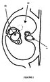
- Figure 1 shows a typical horizontal section through a human thorax clearly indicating the structures of the heart.
- Figure 2 shows a digitally highlighted horizontal section of the ascending aorta taken from a thoracic MRI image
- Figure 3 shows a CAD reconstruction of an ascending aorta and aortic arch.
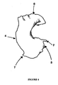
- Figure 4 shows a.CAD reconstruction of an ascending aorta and aortic arch post smoothing
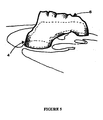
- Figure 5 shows a superimposition of a CAD reconstruction of an ascending aorta with one of the source MRI data files superimposed in the correct spatial position.
- Figure 6 shows an external support in 2 pieces.
- the patient is first scanned using a standard medical MRI unit.
- the scans are taken of the affected structure, e.g. ascending aorta, in such a way as to provide adjacent images substantially axial to the plane of the aorta.
- Poor quality images may be enhanced by multiple imaging and averaging/superposition of identical images.
- Figure 1 below shows a typical horizontal section through a human thorax clearly indicating the structures of the heart.
- Reference numeral 1 indicates the spine at the rear of the thorax
- 2 indicates the left lung and 3 the structures of the heart.
- CAD computer aided design
- Figure 2 shows a similar MRI horizontal section through a human thorax including the spine 1, the left lung 2, the heart 3 and a section of the ascending aorta digitally highlighted at 4.
- Figure 3 shows a CAD reconstruction including the ascending aorta 4, the aortic root containing the aortic valve 5, the aortic arch 6 and the coronary artery origins 7.
- FIG. 4 shows a CAD model of the same ascending aorta 4, aortic root 5, aortic arch 6 and coronary origins 7, post smoothing.
- the CAD model can be validated within some CAD packages by superimposition of base MRI image data onto the finished CAD model.
- Figure 5 shows the superimposition of the CAD reconstruction with an MRI image slice from the source data. Structures visible include the upper part of the ascending aorta 4 and the aortic arch 6.
- the CAD model can then be used to manufacture a tool from which the stent can be manufactured.
- the physical model can be manufactured as follows:
- the CAD model file can be transferred to an appropriate Rapid Prototyping machine, eg a stereo lithography machine (SLA) to produce a physical model of the ascending aorta in a polymer, e.g. UV curable epoxy resin.
- SLA stereo lithography machine
- This model can then be used to produce a mould in a silicone rubber.
- the mould can then be used to produce daughter models of the aorta.
- Other manufacturing techniques can be used, for example selective laser sintering (SLS), CNC machining etc.
- surgical implantation is effected by conventional means using existing surgical procedures to reveal the ascending aorta from the aortic annulus to the arch and accommodating the coronary arteries.
- Said means would include for example surgical sub-procedures taken from the Ross procedure to expose the aortic annulus.
- the stent obtained by the method of the invention conforms morphologically to the contours of the affected artery and when applied effectively provides a clamped sleeve to support its exterior in substantially full contact therewith.
- the clamping of the sleeve also provides an adjustment for the aortic valve in terms of repositioning the valve seat to reinstate or reinforce integrity to prevent leakage at this location, thus avoiding the need to replace the valve.
- the stent obtained by the method of the present invention does not require the high degree of invasive surgery associated with conventional surgical procedures for aortic root resection and valve replacement. Importantly also when the stent is in place although clearly it is in contact with bodily fluids and internal features of the pericardium and neighbouring parts, its external nature means that it is not in contact with blood.
- This very facet of the invention is of high benefit in terms of avoiding the possibility of infection affecting the blood stream and also obviates or significantly reduces the dependency of the patient, having undergone the successful procedure, on aftercare and drugs and treatment associated therewith. Quite apart from these advantages the avoidance of such invasive surgery is clearly less traumatic for the patient.
- Beating heart surgery thus becomes a possibility by virtue of the present invention, which provides a bespoke stent. Indeed with some forms of the stent, for example the spirally wound version, the opportunity arises for keyhole surgery with all the attendant advantages which that offers in terms of non-intrusive procedures with less patient trauma and postoperative care and medication.
Landscapes
- Health & Medical Sciences (AREA)
- Life Sciences & Earth Sciences (AREA)
- Animal Behavior & Ethology (AREA)
- Veterinary Medicine (AREA)
- Vascular Medicine (AREA)
- Public Health (AREA)
- Surgery (AREA)
- Engineering & Computer Science (AREA)
- Biomedical Technology (AREA)
- Heart & Thoracic Surgery (AREA)
- General Health & Medical Sciences (AREA)
- Molecular Biology (AREA)
- Medical Informatics (AREA)
- Nuclear Medicine, Radiotherapy & Molecular Imaging (AREA)
- Reproductive Health (AREA)
- Gastroenterology & Hepatology (AREA)
- Pulmonology (AREA)
- Cardiology (AREA)
- Oral & Maxillofacial Surgery (AREA)
- Transplantation (AREA)
- Prostheses (AREA)
- Media Introduction/Drainage Providing Device (AREA)
Applications Claiming Priority (5)
| Application Number | Priority Date | Filing Date | Title |
|---|---|---|---|
| GB0221781 | 2002-09-19 | ||
| GB0221781A GB0221781D0 (en) | 2002-09-19 | 2002-09-19 | Improvements in or relating to stents |
| GB0308517 | 2003-04-14 | ||
| GB0308517A GB0308517D0 (en) | 2002-09-19 | 2003-04-14 | Improvements in or relating to stents |
| PCT/GB2003/004135 WO2004026178A2 (en) | 2002-09-19 | 2003-09-18 | External stent |
Publications (2)
| Publication Number | Publication Date |
|---|---|
| EP1539035A2 EP1539035A2 (en) | 2005-06-15 |
| EP1539035B1 true EP1539035B1 (en) | 2011-08-17 |
Family
ID=32031883
Family Applications (1)
| Application Number | Title | Priority Date | Filing Date |
|---|---|---|---|
| EP03750965A Expired - Lifetime EP1539035B1 (en) | 2002-09-19 | 2003-09-18 | Improvements relating to stents |
Country Status (7)
| Country | Link |
|---|---|
| US (2) | US20060129228A1 (enExample) |
| EP (1) | EP1539035B1 (enExample) |
| JP (1) | JP4280710B2 (enExample) |
| AU (1) | AU2003269187A1 (enExample) |
| CA (1) | CA2497966C (enExample) |
| PL (1) | PL375863A1 (enExample) |
| WO (1) | WO2004026178A2 (enExample) |
Families Citing this family (37)
| Publication number | Priority date | Publication date | Assignee | Title |
|---|---|---|---|---|
| US8246673B2 (en) | 2002-09-19 | 2012-08-21 | Exstent Limited | External support for a blood vessel |
| PL375863A1 (en) * | 2002-09-19 | 2005-12-12 | Exstent Ltd | Improvements in or relating to stents |
| EP1903537A3 (en) * | 2005-07-20 | 2008-06-11 | Richstone Consulting LLC | A system and a method for simulating a manual interventional operation by a user in a medical procedure |
| US9125732B2 (en) | 2005-07-25 | 2015-09-08 | Vascular Dynamics, Inc. | Devices and methods for control of blood pressure |
| US8923972B2 (en) | 2005-07-25 | 2014-12-30 | Vascular Dynamics, Inc. | Elliptical element for blood pressure reduction |
| US9592136B2 (en) | 2005-07-25 | 2017-03-14 | Vascular Dynamics, Inc. | Devices and methods for control of blood pressure |
| US9642726B2 (en) | 2005-07-25 | 2017-05-09 | Vascular Dynamics, Inc. | Devices and methods for control of blood pressure |
| US20070168066A1 (en) * | 2006-01-18 | 2007-07-19 | Randy-David Burce Grishaber | AAA model for fatigue testing |
| WO2007131552A1 (en) * | 2006-05-17 | 2007-11-22 | Syntach Ag | A patient configured device, a kit and a method for treatment of disorders in the heart rhythm regulation system |
| US20090024152A1 (en) * | 2007-07-17 | 2009-01-22 | Searete Llc, A Limited Liability Corporation Of The State Of Delaware | Custom-fitted blood vessel sleeve |
| US8550344B2 (en) * | 2006-06-16 | 2013-10-08 | The Invention Science Fund I, Llc | Specialty stents with flow control features or the like |
| US8163003B2 (en) * | 2006-06-16 | 2012-04-24 | The Invention Science Fund I, Llc | Active blood vessel sleeve methods and systems |
| US20080172073A1 (en) * | 2006-06-16 | 2008-07-17 | Searete Llc, A Limited Liability Corporation Of The State Of Delaware | Active blood vessel sleeve |
| US8551155B2 (en) * | 2006-06-16 | 2013-10-08 | The Invention Science Fund I, Llc | Stent customization system and method |
| US8095382B2 (en) * | 2006-06-16 | 2012-01-10 | The Invention Science Fund I, Llc | Methods and systems for specifying a blood vessel sleeve |
| US7818084B2 (en) * | 2006-06-16 | 2010-10-19 | The Invention Science Fund, I, LLC | Methods and systems for making a blood vessel sleeve |
| US8478437B2 (en) * | 2006-06-16 | 2013-07-02 | The Invention Science Fund I, Llc | Methods and systems for making a blood vessel sleeve |
| US20080133040A1 (en) * | 2006-06-16 | 2008-06-05 | Searete Llc, A Limited Liability Corporation Of The State Of Delaware | Methods and systems for specifying a blood vessel sleeve |
| US8147537B2 (en) * | 2006-06-16 | 2012-04-03 | The Invention Science Fund I, Llc | Rapid-prototyped custom-fitted blood vessel sleeve |
| US11389171B2 (en) * | 2006-11-21 | 2022-07-19 | David S. Goldsmith | Integrated system for the infixion and retrieval of implants |
| DE102007061301A1 (de) | 2007-12-10 | 2009-06-18 | Aesculap Ag | Ummantelung zur Wiederherstellung der Klappenfunktion variköser Venen und Verwendung der Ummantelung in der Chirurgie |
| US9533078B2 (en) | 2008-06-25 | 2017-01-03 | Boston Scientific Scimed, Inc. | Medical devices containing therapeutic agents |
| CN104665796A (zh) | 2008-09-26 | 2015-06-03 | 血管动力学公司 | 控制血压的装置 |
| US8554350B2 (en) * | 2008-10-15 | 2013-10-08 | Personics Holdings Inc. | Device and method to reduce ear wax clogging of acoustic ports, hearing aid sealing system, and feedback reduction system |
| US8734503B2 (en) | 2008-11-24 | 2014-05-27 | Vascular Graft Solutions Ltd. | External stent |
| US20100268320A1 (en) | 2009-04-17 | 2010-10-21 | Medtronic Vascular, Inc. | Endovascular Implant Having an Integral Graft Component and Method of Manufacture |
| JP5135492B2 (ja) * | 2010-07-01 | 2013-02-06 | 株式会社クロスエフェクト | 中空構造体の樹脂成形体の製造方法及び中子並びに中空構造体の樹脂成形体 |
| US10052218B2 (en) | 2011-04-18 | 2018-08-21 | Vascular Graft Solutions Ltd. | Devices and methods for deploying implantable sleeves over blood vessels |
| US8577693B2 (en) * | 2011-07-13 | 2013-11-05 | The Invention Science Fund I, Llc | Specialty stents with flow control features or the like |
| WO2013050525A1 (en) * | 2011-10-07 | 2013-04-11 | Materialise N.V. | Methods for the manufacture of intraluminal endoprosthesis |
| AU2013326507C1 (en) * | 2012-10-05 | 2018-07-05 | Materialise N.V. | Customized aortic stent device and method of making the same |
| GB201402643D0 (en) | 2014-02-14 | 2014-04-02 | Univ Southampton | A method of mapping images of human disease |
| US10888414B2 (en) | 2019-03-20 | 2021-01-12 | inQB8 Medical Technologies, LLC | Aortic dissection implant |
| WO2021007570A1 (en) * | 2019-07-11 | 2021-01-14 | The Cleveland Clinic Foundation | System and method for model-based stent design and placement |
| DE102019131618B4 (de) * | 2019-11-22 | 2022-03-17 | Novatech Sa | Verfahren zur Herstellung eines Implantats aus einem biokompatiblen Silikon |
| GB2602045B (en) | 2020-12-16 | 2025-02-12 | Exstent Ltd | Model and method of modelling a pulmonary autograft |
| CN118453215A (zh) * | 2024-06-12 | 2024-08-09 | 北京大学人民医院 | 一种升主动脉外支架 |
Family Cites Families (25)
| Publication number | Priority date | Publication date | Assignee | Title |
|---|---|---|---|---|
| US3626947A (en) * | 1970-02-19 | 1971-12-14 | Charles Howard Sparks | Method and apparatus for vein and artery reenforcement |
| GB2090143A (en) | 1980-12-31 | 1982-07-07 | Archibald Steven Lee | Micro-arterial sleeve-grip |
| AU608527B2 (en) * | 1986-07-17 | 1991-04-11 | Vaso Products, Inc | Correction of incompetent venous valves |
| US5245456A (en) * | 1990-10-24 | 1993-09-14 | Nitto Denko Corporation | Birefringent film with nx >nz >ny, process for producing the same, retardation film, elliptically polarizing plate, and liquid crystal display |
| US5246456A (en) * | 1992-06-08 | 1993-09-21 | Wilkinson Lawrence H | Fenestrated gastric pouch |
| US5246546A (en) * | 1992-08-27 | 1993-09-21 | Procter & Gamble Company | Process for applying a thin film containing polysiloxane to tissue paper |
| US5573776A (en) * | 1992-12-02 | 1996-11-12 | Alza Corporation | Oral osmotic device with hydrogel driving member |
| IL106738A (en) * | 1993-08-19 | 1998-02-08 | Mind E M S G Ltd | Device for external correction of deficient valves in venous junctions |
| WO1995007509A1 (en) * | 1993-09-10 | 1995-03-16 | The University Of Queensland | Stereolithographic anatomical modelling process |
| WO1997040755A1 (en) * | 1996-04-29 | 1997-11-06 | W.L. Gore & Associates, Inc. | Device for restoring competence to venous valves |
| GB9710905D0 (en) * | 1997-05-27 | 1997-07-23 | Imperial College | Stent for blood vessel |
| DE69928224T2 (de) * | 1998-01-26 | 2006-08-03 | Anson Medical Ltd., Didcot | Verstärktes implantat |
| ATE266434T1 (de) * | 1998-02-23 | 2004-05-15 | Massachusetts Inst Technology | Bioabbaubare polymere mit formgedächtnis |
| US6165193A (en) * | 1998-07-06 | 2000-12-26 | Microvention, Inc. | Vascular embolization with an expansible implant |
| US6197050B1 (en) * | 1998-09-14 | 2001-03-06 | Heartstent Corporation | Transmyocardial implant with compliance collar |
| GB2344053A (en) | 1998-11-30 | 2000-05-31 | Imperial College | Stents for blood vessels |
| DE60033322T2 (de) | 1999-05-26 | 2007-05-31 | Nec Tokin Corp., Sendai | Vorrichtung zur Gefässeanastomose |
| US6436132B1 (en) * | 2000-03-30 | 2002-08-20 | Advanced Cardiovascular Systems, Inc. | Composite intraluminal prostheses |
| JP2002035135A (ja) * | 2000-07-31 | 2002-02-05 | Manii Kk | ステント及びステントの製造方法 |
| US20020068968A1 (en) * | 2000-08-16 | 2002-06-06 | Thomas Hupp | Virtual stent making process based upon novel enhanced plate tectonics derived from endoluminal mapping |
| US6648911B1 (en) * | 2000-11-20 | 2003-11-18 | Avantec Vascular Corporation | Method and device for the treatment of vulnerable tissue site |
| US6752829B2 (en) * | 2001-01-30 | 2004-06-22 | Scimed Life Systems, Inc. | Stent with channel(s) for containing and delivering a biologically active material and method for manufacturing the same |
| GB0110670D0 (en) * | 2001-05-01 | 2001-06-20 | Anson Medical Ltd | Machine for manufacturing graft-stents |
| WO2004022150A1 (ja) * | 2002-08-23 | 2004-03-18 | Japan As Represented By President Of National Cardiovascular Center | ステント及びその製造方法 |
| PL375863A1 (en) | 2002-09-19 | 2005-12-12 | Exstent Ltd | Improvements in or relating to stents |
-
2003
- 2003-09-18 PL PL03375863A patent/PL375863A1/xx not_active Application Discontinuation
- 2003-09-18 AU AU2003269187A patent/AU2003269187A1/en not_active Abandoned
- 2003-09-18 US US10/527,498 patent/US20060129228A1/en not_active Abandoned
- 2003-09-18 CA CA2497966A patent/CA2497966C/en not_active Expired - Lifetime
- 2003-09-18 EP EP03750965A patent/EP1539035B1/en not_active Expired - Lifetime
- 2003-09-18 JP JP2004537329A patent/JP4280710B2/ja not_active Expired - Lifetime
- 2003-09-18 WO PCT/GB2003/004135 patent/WO2004026178A2/en not_active Ceased
-
2009
- 2009-06-10 US US12/482,080 patent/US8252039B2/en not_active Expired - Lifetime
Also Published As
| Publication number | Publication date |
|---|---|
| WO2004026178A2 (en) | 2004-04-01 |
| WO2004026178A3 (en) | 2004-06-24 |
| CA2497966C (en) | 2011-07-26 |
| CA2497966A1 (en) | 2004-04-01 |
| AU2003269187A8 (en) | 2004-04-08 |
| PL375863A1 (en) | 2005-12-12 |
| JP4280710B2 (ja) | 2009-06-17 |
| US8252039B2 (en) | 2012-08-28 |
| US20090248138A1 (en) | 2009-10-01 |
| AU2003269187A1 (en) | 2004-04-08 |
| US20060129228A1 (en) | 2006-06-15 |
| JP2006500093A (ja) | 2006-01-05 |
| EP1539035A2 (en) | 2005-06-15 |
Similar Documents
| Publication | Publication Date | Title |
|---|---|---|
| EP1539035B1 (en) | Improvements relating to stents | |
| US8246673B2 (en) | External support for a blood vessel | |
| JP2006500093A5 (enExample) | ||
| US20250332794A1 (en) | Fenestration template for endovascular repair of aortic aneurysms | |
| US11096726B2 (en) | Composite internal fixators | |
| EP0722588B1 (en) | Stereolithographic anatomical modelling process | |
| US8414591B2 (en) | Surgical guiding tool, methods for manufacture and uses thereof | |
| JP2021184917A (ja) | 個人に合わせられたプロテーゼおよび使用の方法 | |
| EP3223753A1 (en) | Bone screw | |
| WO2014090908A1 (en) | Surgical guiding tools for orthopedic surgery and systems and methods of manufacturing the same | |
| WO2013055203A1 (en) | Method to provide at least one patient specific device to be used for bone correction, a treatment kit, a method of operating a data-processing system, a computer program, and a correction and fixation device and a cutting assisting device for bone correction. | |
| US12251299B2 (en) | Method for automated production of a vascular endoprosthesis | |
| US11992400B2 (en) | Stent graft and method for producing same | |
| ES2369533T3 (es) | Mejoras relativas a stents. | |
| Brennan | Production of anatomical models from CT scan data | |
| Jeyaraj et al. | Cutting Edge Era of Additively Manufactured Patient Specific Titanium Implants for Expeditious Extensive Cranioplasties |
Legal Events
| Date | Code | Title | Description |
|---|---|---|---|
| PUAI | Public reference made under article 153(3) epc to a published international application that has entered the european phase |
Free format text: ORIGINAL CODE: 0009012 |
|
| 17P | Request for examination filed |
Effective date: 20050331 |
|
| AK | Designated contracting states |
Kind code of ref document: A2 Designated state(s): AT BE BG CH CY CZ DE DK EE ES FI FR GB GR HU IE IT LI LU MC NL PT RO SE SI SK TR |
|
| AX | Request for extension of the european patent |
Extension state: AL LT LV MK |
|
| DAX | Request for extension of the european patent (deleted) | ||
| 17Q | First examination report despatched |
Effective date: 20090902 |
|
| GRAP | Despatch of communication of intention to grant a patent |
Free format text: ORIGINAL CODE: EPIDOSNIGR1 |
|
| RTI1 | Title (correction) |
Free format text: IMPROVEMENTS RELATING TO STENTS |
|
| GRAS | Grant fee paid |
Free format text: ORIGINAL CODE: EPIDOSNIGR3 |
|
| GRAA | (expected) grant |
Free format text: ORIGINAL CODE: 0009210 |
|
| RAP1 | Party data changed (applicant data changed or rights of an application transferred) |
Owner name: EXSTENT LIMITED |
|
| AK | Designated contracting states |
Kind code of ref document: B1 Designated state(s): AT BE BG CH CY CZ DE DK EE ES FI FR GB GR HU IE IT LI LU MC NL PT RO SE SI SK TR |
|
| REG | Reference to a national code |
Ref country code: GB Ref legal event code: FG4D |
|
| REG | Reference to a national code |
Ref country code: CH Ref legal event code: EP |
|
| REG | Reference to a national code |
Ref country code: IE Ref legal event code: FG4D |
|
| REG | Reference to a national code |
Ref country code: DE Ref legal event code: R096 Ref document number: 60338071 Country of ref document: DE Effective date: 20111027 |
|
| REG | Reference to a national code |
Ref country code: SE Ref legal event code: TRGR |
|
| REG | Reference to a national code |
Ref country code: NL Ref legal event code: T3 |
|
| REG | Reference to a national code |
Ref country code: ES Ref legal event code: FG2A Ref document number: 2369533 Country of ref document: ES Kind code of ref document: T3 Effective date: 20111201 |
|
| REG | Reference to a national code |
Ref country code: DK Ref legal event code: T3 |
|
| PG25 | Lapsed in a contracting state [announced via postgrant information from national office to epo] |
Ref country code: FI Free format text: LAPSE BECAUSE OF FAILURE TO SUBMIT A TRANSLATION OF THE DESCRIPTION OR TO PAY THE FEE WITHIN THE PRESCRIBED TIME-LIMIT Effective date: 20110817 Ref country code: PT Free format text: LAPSE BECAUSE OF FAILURE TO SUBMIT A TRANSLATION OF THE DESCRIPTION OR TO PAY THE FEE WITHIN THE PRESCRIBED TIME-LIMIT Effective date: 20111219 |
|
| REG | Reference to a national code |
Ref country code: AT Ref legal event code: MK05 Ref document number: 520370 Country of ref document: AT Kind code of ref document: T Effective date: 20110817 |
|
| PG25 | Lapsed in a contracting state [announced via postgrant information from national office to epo] |
Ref country code: CY Free format text: LAPSE BECAUSE OF FAILURE TO SUBMIT A TRANSLATION OF THE DESCRIPTION OR TO PAY THE FEE WITHIN THE PRESCRIBED TIME-LIMIT Effective date: 20110817 Ref country code: AT Free format text: LAPSE BECAUSE OF FAILURE TO SUBMIT A TRANSLATION OF THE DESCRIPTION OR TO PAY THE FEE WITHIN THE PRESCRIBED TIME-LIMIT Effective date: 20110817 Ref country code: SI Free format text: LAPSE BECAUSE OF FAILURE TO SUBMIT A TRANSLATION OF THE DESCRIPTION OR TO PAY THE FEE WITHIN THE PRESCRIBED TIME-LIMIT Effective date: 20110817 Ref country code: GR Free format text: LAPSE BECAUSE OF FAILURE TO SUBMIT A TRANSLATION OF THE DESCRIPTION OR TO PAY THE FEE WITHIN THE PRESCRIBED TIME-LIMIT Effective date: 20111118 |
|
| PG25 | Lapsed in a contracting state [announced via postgrant information from national office to epo] |
Ref country code: SK Free format text: LAPSE BECAUSE OF FAILURE TO SUBMIT A TRANSLATION OF THE DESCRIPTION OR TO PAY THE FEE WITHIN THE PRESCRIBED TIME-LIMIT Effective date: 20110817 Ref country code: MC Free format text: LAPSE BECAUSE OF NON-PAYMENT OF DUE FEES Effective date: 20110930 Ref country code: CZ Free format text: LAPSE BECAUSE OF FAILURE TO SUBMIT A TRANSLATION OF THE DESCRIPTION OR TO PAY THE FEE WITHIN THE PRESCRIBED TIME-LIMIT Effective date: 20110817 |
|
| REG | Reference to a national code |
Ref country code: CH Ref legal event code: PL |
|
| PG25 | Lapsed in a contracting state [announced via postgrant information from national office to epo] |
Ref country code: EE Free format text: LAPSE BECAUSE OF FAILURE TO SUBMIT A TRANSLATION OF THE DESCRIPTION OR TO PAY THE FEE WITHIN THE PRESCRIBED TIME-LIMIT Effective date: 20110817 Ref country code: RO Free format text: LAPSE BECAUSE OF FAILURE TO SUBMIT A TRANSLATION OF THE DESCRIPTION OR TO PAY THE FEE WITHIN THE PRESCRIBED TIME-LIMIT Effective date: 20110817 |
|
| PLBE | No opposition filed within time limit |
Free format text: ORIGINAL CODE: 0009261 |
|
| STAA | Information on the status of an ep patent application or granted ep patent |
Free format text: STATUS: NO OPPOSITION FILED WITHIN TIME LIMIT |
|
| 26N | No opposition filed |
Effective date: 20120521 |
|
| PG25 | Lapsed in a contracting state [announced via postgrant information from national office to epo] |
Ref country code: CH Free format text: LAPSE BECAUSE OF NON-PAYMENT OF DUE FEES Effective date: 20110930 Ref country code: LI Free format text: LAPSE BECAUSE OF NON-PAYMENT OF DUE FEES Effective date: 20110930 |
|
| REG | Reference to a national code |
Ref country code: DE Ref legal event code: R097 Ref document number: 60338071 Country of ref document: DE Effective date: 20120521 |
|
| PG25 | Lapsed in a contracting state [announced via postgrant information from national office to epo] |
Ref country code: LU Free format text: LAPSE BECAUSE OF NON-PAYMENT OF DUE FEES Effective date: 20110918 |
|
| PG25 | Lapsed in a contracting state [announced via postgrant information from national office to epo] |
Ref country code: BG Free format text: LAPSE BECAUSE OF FAILURE TO SUBMIT A TRANSLATION OF THE DESCRIPTION OR TO PAY THE FEE WITHIN THE PRESCRIBED TIME-LIMIT Effective date: 20111117 |
|
| PG25 | Lapsed in a contracting state [announced via postgrant information from national office to epo] |
Ref country code: TR Free format text: LAPSE BECAUSE OF FAILURE TO SUBMIT A TRANSLATION OF THE DESCRIPTION OR TO PAY THE FEE WITHIN THE PRESCRIBED TIME-LIMIT Effective date: 20110817 |
|
| PG25 | Lapsed in a contracting state [announced via postgrant information from national office to epo] |
Ref country code: HU Free format text: LAPSE BECAUSE OF FAILURE TO SUBMIT A TRANSLATION OF THE DESCRIPTION OR TO PAY THE FEE WITHIN THE PRESCRIBED TIME-LIMIT Effective date: 20110817 |
|
| REG | Reference to a national code |
Ref country code: FR Ref legal event code: PLFP Year of fee payment: 14 |
|
| REG | Reference to a national code |
Ref country code: FR Ref legal event code: PLFP Year of fee payment: 15 |
|
| REG | Reference to a national code |
Ref country code: FR Ref legal event code: PLFP Year of fee payment: 16 |
|
| PGFP | Annual fee paid to national office [announced via postgrant information from national office to epo] |
Ref country code: SE Payment date: 20220930 Year of fee payment: 20 Ref country code: NL Payment date: 20220930 Year of fee payment: 20 Ref country code: IE Payment date: 20220930 Year of fee payment: 20 Ref country code: GB Payment date: 20220929 Year of fee payment: 20 Ref country code: DK Payment date: 20220930 Year of fee payment: 20 |
|
| PGFP | Annual fee paid to national office [announced via postgrant information from national office to epo] |
Ref country code: FR Payment date: 20220930 Year of fee payment: 20 Ref country code: BE Payment date: 20220930 Year of fee payment: 20 |
|
| PGFP | Annual fee paid to national office [announced via postgrant information from national office to epo] |
Ref country code: IT Payment date: 20220930 Year of fee payment: 20 Ref country code: ES Payment date: 20221006 Year of fee payment: 20 Ref country code: DE Payment date: 20221007 Year of fee payment: 20 |
|
| REG | Reference to a national code |
Ref country code: DE Ref legal event code: R071 Ref document number: 60338071 Country of ref document: DE |
|
| REG | Reference to a national code |
Ref country code: NL Ref legal event code: MK Effective date: 20230917 |
|
| REG | Reference to a national code |
Ref country code: DK Ref legal event code: EUP Expiry date: 20230918 |
|
| REG | Reference to a national code |
Ref country code: ES Ref legal event code: FD2A Effective date: 20230927 |
|
| REG | Reference to a national code |
Ref country code: BE Ref legal event code: MK Effective date: 20230918 |
|
| REG | Reference to a national code |
Ref country code: GB Ref legal event code: PE20 Expiry date: 20230917 |
|
| REG | Reference to a national code |
Ref country code: IE Ref legal event code: MK9A |
|
| PG25 | Lapsed in a contracting state [announced via postgrant information from national office to epo] |
Ref country code: GB Free format text: LAPSE BECAUSE OF EXPIRATION OF PROTECTION Effective date: 20230917 Ref country code: ES Free format text: LAPSE BECAUSE OF EXPIRATION OF PROTECTION Effective date: 20230919 |
|
| REG | Reference to a national code |
Ref country code: SE Ref legal event code: EUG |
|
| PG25 | Lapsed in a contracting state [announced via postgrant information from national office to epo] |
Ref country code: IE Free format text: LAPSE BECAUSE OF EXPIRATION OF PROTECTION Effective date: 20230918 |