EP1539012B1 - ENDOVASKULûRE BEHANDLUNGSVORRICHTUNG MIT FASERSPITZEN-ABSTANDSELEMENT - Google Patents
ENDOVASKULûRE BEHANDLUNGSVORRICHTUNG MIT FASERSPITZEN-ABSTANDSELEMENT Download PDFInfo
- Publication number
- EP1539012B1 EP1539012B1 EP03763292.4A EP03763292A EP1539012B1 EP 1539012 B1 EP1539012 B1 EP 1539012B1 EP 03763292 A EP03763292 A EP 03763292A EP 1539012 B1 EP1539012 B1 EP 1539012B1
- Authority
- EP
- European Patent Office
- Prior art keywords
- spacer
- treatment device
- optical fiber
- vein
- laser treatment
- Prior art date
- Legal status (The legal status is an assumption and is not a legal conclusion. Google has not performed a legal analysis and makes no representation as to the accuracy of the status listed.)
- Expired - Lifetime
Links
- 125000006850 spacer group Chemical group 0.000 title claims description 100
- 239000000835 fiber Substances 0.000 title claims description 96
- 238000012276 Endovascular treatment Methods 0.000 title description 3
- 239000013307 optical fiber Substances 0.000 claims description 91
- 210000003462 vein Anatomy 0.000 claims description 62
- 238000013532 laser treatment Methods 0.000 claims description 52
- 239000008280 blood Substances 0.000 claims description 15
- 210000004369 blood Anatomy 0.000 claims description 15
- HLXZNVUGXRDIFK-UHFFFAOYSA-N nickel titanium Chemical compound [Ti].[Ti].[Ti].[Ti].[Ti].[Ti].[Ti].[Ti].[Ti].[Ti].[Ti].[Ni].[Ni].[Ni].[Ni].[Ni].[Ni].[Ni].[Ni].[Ni].[Ni].[Ni].[Ni].[Ni].[Ni] HLXZNVUGXRDIFK-UHFFFAOYSA-N 0.000 claims description 2
- 229910001000 nickel titanium Inorganic materials 0.000 claims description 2
- 239000012781 shape memory material Substances 0.000 claims 3
- 238000000034 method Methods 0.000 description 25
- 238000011282 treatment Methods 0.000 description 17
- 230000023597 hemostasis Effects 0.000 description 15
- 206010046996 Varicose vein Diseases 0.000 description 11
- 230000006835 compression Effects 0.000 description 11
- 238000007906 compression Methods 0.000 description 11
- 230000006870 function Effects 0.000 description 9
- 239000012530 fluid Substances 0.000 description 8
- 230000007246 mechanism Effects 0.000 description 8
- 230000004888 barrier function Effects 0.000 description 7
- 210000004204 blood vessel Anatomy 0.000 description 7
- 210000003752 saphenous vein Anatomy 0.000 description 7
- 208000027185 varicose disease Diseases 0.000 description 7
- 238000002347 injection Methods 0.000 description 5
- 239000007924 injection Substances 0.000 description 5
- 238000003780 insertion Methods 0.000 description 5
- 230000037431 insertion Effects 0.000 description 5
- 229920000642 polymer Polymers 0.000 description 4
- 239000000126 substance Substances 0.000 description 4
- FAPWRFPIFSIZLT-UHFFFAOYSA-M Sodium chloride Chemical compound [Na+].[Cl-] FAPWRFPIFSIZLT-UHFFFAOYSA-M 0.000 description 3
- 239000000463 material Substances 0.000 description 3
- 239000011780 sodium chloride Substances 0.000 description 3
- 238000003466 welding Methods 0.000 description 3
- 239000004677 Nylon Substances 0.000 description 2
- 206010068149 Vessel perforation Diseases 0.000 description 2
- 230000017531 blood circulation Effects 0.000 description 2
- 239000000919 ceramic Substances 0.000 description 2
- 238000005253 cladding Methods 0.000 description 2
- 238000013461 design Methods 0.000 description 2
- 238000009826 distribution Methods 0.000 description 2
- 230000009977 dual effect Effects 0.000 description 2
- 238000010438 heat treatment Methods 0.000 description 2
- 239000004816 latex Substances 0.000 description 2
- 229920000126 latex Polymers 0.000 description 2
- 230000017074 necrotic cell death Effects 0.000 description 2
- 229920001778 nylon Polymers 0.000 description 2
- 238000002360 preparation method Methods 0.000 description 2
- 238000007789 sealing Methods 0.000 description 2
- 208000024891 symptom Diseases 0.000 description 2
- 230000003685 thermal hair damage Effects 0.000 description 2
- 230000000451 tissue damage Effects 0.000 description 2
- 231100000827 tissue damage Toxicity 0.000 description 2
- 238000002604 ultrasonography Methods 0.000 description 2
- UCTWMZQNUQWSLP-VIFPVBQESA-N (R)-adrenaline Chemical compound CNC[C@H](O)C1=CC=C(O)C(O)=C1 UCTWMZQNUQWSLP-VIFPVBQESA-N 0.000 description 1
- 229930182837 (R)-adrenaline Natural products 0.000 description 1
- 206010002091 Anaesthesia Diseases 0.000 description 1
- 208000034656 Contusions Diseases 0.000 description 1
- 206010015866 Extravasation Diseases 0.000 description 1
- 208000032843 Hemorrhage Diseases 0.000 description 1
- NNJVILVZKWQKPM-UHFFFAOYSA-N Lidocaine Chemical compound CCN(CC)CC(=O)NC1=C(C)C=CC=C1C NNJVILVZKWQKPM-UHFFFAOYSA-N 0.000 description 1
- 206010048591 Post thrombotic syndrome Diseases 0.000 description 1
- 208000003251 Pruritus Diseases 0.000 description 1
- 206010040943 Skin Ulcer Diseases 0.000 description 1
- 208000025865 Ulcer Diseases 0.000 description 1
- 238000010521 absorption reaction Methods 0.000 description 1
- 230000004308 accommodation Effects 0.000 description 1
- 230000009471 action Effects 0.000 description 1
- 230000003213 activating effect Effects 0.000 description 1
- 230000004913 activation Effects 0.000 description 1
- 230000002411 adverse Effects 0.000 description 1
- 230000037005 anaesthesia Effects 0.000 description 1
- 208000003455 anaphylaxis Diseases 0.000 description 1
- 208000034158 bleeding Diseases 0.000 description 1
- 230000000740 bleeding effect Effects 0.000 description 1
- 239000002537 cosmetic Substances 0.000 description 1
- 230000006378 damage Effects 0.000 description 1
- 230000003247 decreasing effect Effects 0.000 description 1
- 208000037265 diseases, disorders, signs and symptoms Diseases 0.000 description 1
- 239000003814 drug Substances 0.000 description 1
- 229940079593 drug Drugs 0.000 description 1
- 229920001971 elastomer Polymers 0.000 description 1
- 239000013536 elastomeric material Substances 0.000 description 1
- 229960005139 epinephrine Drugs 0.000 description 1
- 230000036251 extravasation Effects 0.000 description 1
- 210000003414 extremity Anatomy 0.000 description 1
- 239000002783 friction material Substances 0.000 description 1
- 238000002695 general anesthesia Methods 0.000 description 1
- 239000003193 general anesthetic agent Substances 0.000 description 1
- 239000002085 irritant Substances 0.000 description 1
- 231100000021 irritant Toxicity 0.000 description 1
- 230000007803 itching Effects 0.000 description 1
- 238000002647 laser therapy Methods 0.000 description 1
- 229960004194 lidocaine Drugs 0.000 description 1
- 230000000670 limiting effect Effects 0.000 description 1
- 208000005592 lipodermatosclerosis Diseases 0.000 description 1
- 210000003141 lower extremity Anatomy 0.000 description 1
- 238000005259 measurement Methods 0.000 description 1
- 238000002844 melting Methods 0.000 description 1
- 230000008018 melting Effects 0.000 description 1
- 238000012986 modification Methods 0.000 description 1
- 230000004048 modification Effects 0.000 description 1
- 210000005036 nerve Anatomy 0.000 description 1
- 238000013021 overheating Methods 0.000 description 1
- 230000036407 pain Effects 0.000 description 1
- 230000036961 partial effect Effects 0.000 description 1
- 208000001297 phlebitis Diseases 0.000 description 1
- 239000002861 polymer material Substances 0.000 description 1
- 229920001296 polysiloxane Polymers 0.000 description 1
- 238000003825 pressing Methods 0.000 description 1
- 230000001681 protective effect Effects 0.000 description 1
- 238000011084 recovery Methods 0.000 description 1
- 230000004044 response Effects 0.000 description 1
- 238000007632 sclerotherapy Methods 0.000 description 1
- 238000010186 staining Methods 0.000 description 1
- 229910001220 stainless steel Inorganic materials 0.000 description 1
- 239000010935 stainless steel Substances 0.000 description 1
- 238000001356 surgical procedure Methods 0.000 description 1
- 230000008961 swelling Effects 0.000 description 1
- 238000007669 thermal treatment Methods 0.000 description 1
- 230000001732 thrombotic effect Effects 0.000 description 1
- 238000012546 transfer Methods 0.000 description 1
- 230000000472 traumatic effect Effects 0.000 description 1
- 230000036269 ulceration Effects 0.000 description 1
- 238000007631 vascular surgery Methods 0.000 description 1
- 201000002282 venous insufficiency Diseases 0.000 description 1
Images


Classifications
-
- A—HUMAN NECESSITIES
- A61—MEDICAL OR VETERINARY SCIENCE; HYGIENE
- A61B—DIAGNOSIS; SURGERY; IDENTIFICATION
- A61B18/00—Surgical instruments, devices or methods for transferring non-mechanical forms of energy to or from the body
- A61B18/18—Surgical instruments, devices or methods for transferring non-mechanical forms of energy to or from the body by applying electromagnetic radiation, e.g. microwaves
- A61B18/20—Surgical instruments, devices or methods for transferring non-mechanical forms of energy to or from the body by applying electromagnetic radiation, e.g. microwaves using laser
- A61B18/22—Surgical instruments, devices or methods for transferring non-mechanical forms of energy to or from the body by applying electromagnetic radiation, e.g. microwaves using laser the beam being directed along or through a flexible conduit, e.g. an optical fibre; Couplings or hand-pieces therefor
- A61B18/24—Surgical instruments, devices or methods for transferring non-mechanical forms of energy to or from the body by applying electromagnetic radiation, e.g. microwaves using laser the beam being directed along or through a flexible conduit, e.g. an optical fibre; Couplings or hand-pieces therefor with a catheter
-
- A—HUMAN NECESSITIES
- A61—MEDICAL OR VETERINARY SCIENCE; HYGIENE
- A61B—DIAGNOSIS; SURGERY; IDENTIFICATION
- A61B17/00—Surgical instruments, devices or methods
- A61B17/22—Implements for squeezing-off ulcers or the like on inner organs of the body; Implements for scraping-out cavities of body organs, e.g. bones; for invasive removal or destruction of calculus using mechanical vibrations; for removing obstructions in blood vessels, not otherwise provided for
- A61B2017/22051—Implements for squeezing-off ulcers or the like on inner organs of the body; Implements for scraping-out cavities of body organs, e.g. bones; for invasive removal or destruction of calculus using mechanical vibrations; for removing obstructions in blood vessels, not otherwise provided for with an inflatable part, e.g. balloon, for positioning, blocking, or immobilisation
- A61B2017/22065—Functions of balloons
- A61B2017/22068—Centering
-
- A—HUMAN NECESSITIES
- A61—MEDICAL OR VETERINARY SCIENCE; HYGIENE
- A61B—DIAGNOSIS; SURGERY; IDENTIFICATION
- A61B18/00—Surgical instruments, devices or methods for transferring non-mechanical forms of energy to or from the body
- A61B2018/00053—Mechanical features of the instrument of device
- A61B2018/00273—Anchoring means for temporary attachment of a device to tissue
- A61B2018/00279—Anchoring means for temporary attachment of a device to tissue deployable
- A61B2018/00285—Balloons
Definitions
- the present invention relates to a medical device apparatus for treatment of blood vessels. More particularly, the present invention relates to a laser fiber device for endovenous thermal treatment of varicose veins.
- Veins are thin-walled and contain one-way valves that control blood flow. Normally, the valves open to allow blood to flow into the deeper veins and close to prevent back-flow into the superficial veins. When the valves are malfunctioning or only partially functioning, however, they no longer prevent the back-flow of blood into the superficial veins. As a result, venous pressure builds at the site of the faulty valves. Because the veins are thin walled and not able to withstand the increased pressure, they become what are known as varicose veins which are veins that are dilated, tortuous or engorged.
- varicose veins of the lower extremities is one of the most common medical conditions of the adult population. It is estimated that varicose veins affect approximately 25% of adult females and 10% of males. Symptoms include discomfort, aching of the legs, itching, cosmetic deformities, and swelling. If left untreated, varicose veins may cause medical complications such as bleeding, phlebitis, ulcerations, thrombi and lipodermatosclerosis.
- Temporary treatments involve use of compression stockings and elevation of the diseased extremities. While providing temporary relief of symptoms, these techniques do not correct the underlying cause, that is the faulty valves.
- Permanent treatments include surgical excision of the diseased segments, ambulatory phlebectomy, and occlusion of the vein through chemical or thermal means.
- Surgical excision requires general anesthesia and a long recovery period. Even with its high clinical success rate, surgical excision is rapidly becoming an outmoded technique due to the high costs of treatment and complication risks from surgery.
- Ambulatory phlebectomy involves avulsion of the varicose vein segment using multiple stab incisions through the skin. The procedure is done on an outpatient basis, but is still relatively expensive due to the length of time required to perform the procedure.
- Chemical occlusion also known as sclerotherapy, is an in-office procedure involving the injection of an irritant chemical into the vein.
- the chemical acts upon the inner lining of the vein walls causing them to occlude and block blood flow.
- complications can be severe including skin ulceration, anaphylactic reactions and permanent skin staining. Treatment is limited to veins of a particular size range.
- Endovascular laser therapy is a relatively new treatment technique for venous reflux diseases.
- the laser energy is delivered by a flexible optical fiber that is percutaneously inserted into the diseased vein prior to energy delivery.
- An introducer catheter or sheath is typically first inserted into the saphenous vein at a distal location and advanced to within a few centimeters of the saphenous-femoral junction of the greater saphenous vein. Once the sheath is properly positioned, a flexible optical fiber is inserted into the lumen of the sheath and advanced until the fiber tip is near the sheath tip but still protected within the sheath lumen.
- the sheath Prior to laser activation, the sheath is withdrawn approximately 1- 4 centimeters to expose the distal tip of the optical fiber. After the fiber tip has been exposed the correct distance beyond the sheath tip, a laser generator is activated causing laser energy to be emitted from the bare flat tip of the fiber into the vessel. The energy contacts the blood causing hot bubbles of gas to be created. The gas bubbles transfer thermal energy to the vein wall, causing cell necrosis and eventual vein collapse. With the laser generator turned on, the optical fiber and sheath are slowly withdrawn as a single unit until the entire diseased segment of the vessel has been treated.
- a typical laser system uses a 600-micron optical fiber covered with a thick polymer jacket.
- the fiber extends unprotected from the polymer jacket, approximately 4mm in length at the tip of the optical fiber.
- the fiber's tip is ground and polished to form a flat face at its extreme distal end.
- the flat face is necessary to ensure energy is directed in a forward direction rather than radially, which would occur if the fiber tip configuration were radiused.
- the flat face of the optical fiber tip directs the laser energy from the fiber to the vein's lumen rather than directly to the vein walls.
- Another problem created by the prior art methods involving contact between the fiber tip and vessel wall is that inadequate energy is delivered to the non-contact segments of the diseased vein. Inadequately heated vein tissue may not necrose or collapse, resulting in incomplete treatment. With the fiber tip in contact with the vessel wall rather than the bloodstream, hot gas bubbles are not created. The bubble is the mechanism by which the 360 degree circumference of the vessel wall is damaged. Without the bubbles, it is possible for some vein tissue to be under heated or not heated at all, resulting in incomplete treatment and possible recanalization of the vessel.
- an endovascular treatment device which protects the optical fiber tip from direct contact with the inner wall of vessel during the emission of laser energy to ensure consistent thermal heating across the entire vessel circumference thus avoiding vessel perforation or incomplete vessel collapse.
- an endovascular laser treatment device as set forth in Claim 1.
- the device includes a spacer arranged near a distal end of the optical fiber.
- the spacer positions the distal end of the optical fiber away from the inner wall of the blood vessel during delivery of laser energy through the optical fiber.
- the spacer is in an undeployed state while being inserted into the blood vessel. Once the undeployed spacer is inserted into the vessel, the spacer is placed into a deployed state where it positions the optical fiber end away from the inner vessel wall.
- the spacer is attached to the optical fiber near its distal end.
- the fiber is inserted into the blood vessel with the undeployed spacer attached at its end. Once, the undeployed spacer is inserted into the vessel, the spacer is placed into the deployed state.
- the spacer may includes a plurality of ribs which expand in a radial direction within the vessel.
- the spacer is separate from the optical fiber.
- the spacer is part of an outer tube that surrounds an inner tube.
- the inner tube is adapted to receive the optical fiber.
- the outer tube has its distal portion attached to the first tube and the spacer is arranged near the distal portion of the outer tube. The spacer is placed into the deployed state when the outer tube is moved relative to the inner tube.
- the spacer prevents contact between the fiber tip and the inner vessel wall to direct the laser energy forward into the vessel lumen and bloodstream in order to avoid the application of laser energy directly to the vessel wall.
- the laser energy applied to the blood stream creates hot gas bubbles.
- thermal energy is transferred to the wall, causing tissue damage and ultimate collapse of the vessel.
- the spacer of the present invention positions the fiber tip away from the vessel wall, the present invention avoids the over heating or under heating of the inner vessel wall that occurs when the fiber tip comes in direct contact with the vessel.
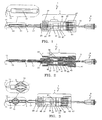
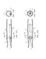
- the endovascular laser treatment device 1 shown in FIG. 1 and FIG. 2 includes an optical fiber 3 which is comprised of clad-coated fiber 13 and jacket 15.
- the device also includes an outer sleeve 17, fitting assembly 7, which also acts as a deployment mechanism, compression gasket 45 and a compression cap 47.
- the optical fiber 3 transmits the laser energy from a laser generator (not shown) into a vessel.
- the fitting assembly 7 acts as a deployment mechanism for a spacer element to be discussed in detail later herein.
- the compression gasket 45 and compression cap 47 provide a sealing function and when compressed, generate friction sufficient to maintain the position of the optical fiber 3.
- the optical fiber 3 is typically comprised of a 600-micron laser fiber 13 encased in a thick polymer jacket 15 for the entire length of the fiber 3 except for approximately 4mm at the distal end.
- the jacket 15 prevents the fragile fiber from breaking during use.
- a thin intermediate cladding (not shown) creates a barrier through which the laser energy cannot penetrate, thus causing the energy to move longitudinally through the fiber 3 to the distal end where the laser energy is emitted.
- the bare fiber 13 extends unprotected from the polymer jacket 15.
- the proximal end of the optical fiber 3 is connected to a SMA or similar-type connector 9, which can be attached to the laser generator (not shown).
- the optical fiber tip is ground and polished to form a flat face 11.
- the flat face 11 of the optical fiber 3 tip directs the laser energy from the fiber in a longitudinal direction.
- the outer sleeve 17 is a tubular structure preferably comprised of a flexible, low-friction material such as nylon.
- the outer sleeve 17 is arranged coaxially around the optical fiber 3.
- the outer sleeve 17 inner diameter is preferably about 1.14 mm (0.045"), although other diameters can be used for different optical fiber sizes.
- the outer diameter of the sleeve 17 is sized to fit within a standard 5F sheath.
- a sleeve 17 dimensioned with a 1.68 mm (0.066") outer diameter should slidably fit within the lumen of a 5F sheath, which has an approximate inner diameter of 1.78 mm (0.070").
- the outer sleeve 17 is coaxially arranged around the optical fiber 3 and permanently attached to the fiber 3 at the distal end of the sleeve 17 at point 23 which defines a bonding zone between the fiber 3 and the distal end of the sleeve 17.
- the outer sleeve 17 can be moved longitudinally relative to the optical fiber 3 except at the point 23.
- the sleeve 17 includes a plurality of longitudinal slits 21 in the tubing at the distal end to define a plurality of ribs 19 each arranged between two adjacent slits. Preferably, there are three to six slits while the embodiment shown has five slits to define five ribs 19.
- the ribs 19 disposed near the distal tip 11 of the optical fiber 3 define a spacer element that positions the distal tip 11 away from the inner wall of the vessel.
- the slits 21 expand radially outward to deploy the spacer element 19, as will be explained in more detail below.
- the sleeve 17 is permanently bonded to the distal fitting component 33 at the sleeve/fitting assembly bond point 25, as more clearly shown in FIG. 2 .
- a fitting assembly 7 positioned at the proximal end of the outer sleeve 17 provides the mechanism by which the spacer element 19 is moved from an undeployed to deployed position.
- the fitting assembly 7 is comprised of a distal fitting component 33, a proximal fitting component 35 and a compression cap 47 threadably connected to the proximal fitting component 35.
- the two fitting components 33 and 35 are permanently attached together at bond point 41.
- the distal fitting component 33 includes a male luer connector 27 or other similar type connection element which functions to connect the endovascular laser treatment device 1 to other commonly used medical devices such as a hemostasis sheath.
- the outer sleeve shaft 17 is bonded to the male luer connector 27 of the distal fitting component 33 at point 25.
- the distal fitting component 33 has a longitudinal channel 39 through which the optical fiber 3 is positioned.
- the proximal fitting component 35 also includes a longitudinal channel 39, as shown in FIG. 2 , through which the optical fiber 3 is positioned.
- the proximal end of the fitting component 35 includes a cavity into which a gasket 45 is positioned.
- the gasket 45 is made of silicone or other compressible material with a central opening through which the optical fiber 3 passes.
- the gasket 45 provides the dual functions of sealing the channel 39 and providing friction sufficient to maintain the longitudinal position of the optical fiber 3 within the channel 39.
- the gasket compression threads 43 at the proximal end of fitting component 35 provide an axially moveable connection between the fitting 35 and the compression cap 47.
- the proximal fitting component 35 and the distal fitting component 33 form a hollow positioning chamber 31 as shown in FIG. 2 .
- a positioning element 29 that is permanently attached to the optical fiber jacket 15 at bond point 37.
- the positioning element 29 provides the function of limiting the longitudinal movement of the combined fitting assembly 7 / outer sleeve 17 relative to the optical fiber 3.
- the positioning element 29 is in contact with the distal chamber face 65. Longitudinal movement of fitting assembly causes the positioning element 29 to be repositioned within the chamber 31. Forward longitudinal movement of the fitting 7/ outer sleeve 17 is stopped when the positioning element 29 comes in contact with proximal chamber face 67.
- the spacer element 19 When the positioning element 29 is against the proximal chamber face 67, the spacer element 19 is fully deployed as illustrated in FIG. 3 . In this position, the spacer ribs 19 are expanded radially outward, forming a space barrier between the fiber tip 11 and the inner vein wall.
- the mechanism for expansion is based on the forward longitudinal movement of the outer sleeve 17 proximal to the fiber/sleeve distal bond point 23. Since the optical fiber 3 is held stationary during deployment, and the fiber is permanently bonded to the sleeve 17 at point 23, the portion of the sleeve 17 within the slit zone expands as the sleeve is pushed forward.
- the device 1 is designed to allow expansion of the slit zone to a maximum predetermined diameter. Alternatively, an intermediate expansion diameter can be achieved by controlling the amount of longitudinal movement within the chamber 31.
- the spacer element 19 provides several important advantages among others.
- the outer diameter and profile of the spacer element 19 is equal to the outer sleeve 17, allowing for easy insertion and positioning within the vein.
- the fitting assembly 7 provides the user with an easy, simple means for deploying the spacer element 19 while maintaining the position of the fiber tip 11 stationary within the vein.
- the spacer element 19 creates a barrier between the fiber tip 11 and the inner vein wall, thereby minimizing unequal laser energy distribution.
- FIGS. 1 - 3 may be used with a standard hemostasis introducer sheath.
- Endovenous laser sheaths are typically 45 centimeters in length, although 60 and 65 centimeter sheaths are also well known in the art.
- the length of the endovascular laser treatment device 1 is determined based on the length of the sheath being used for the procedure.
- the endovascular laser treatment device 1 can be sized to fit standard-length sheaths or custom-length sheaths.
- the assembly 1 can be provided by itself or in a package that includes either the standard length sheath or custom-length sheath.
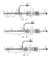
- FIGS. 4A-4C show the endovascular laser treatment device 1 with a hemostasis introducer sheath 49.
- the hemostasis introducer sheath assembly 49 is comprised of a sheath shaft 53, a sheath distal tip 51, a sidearm port 57 with connecting tubing, a stopcock assembly 61, and a hemostasis valve gasket 59 housed within proximal opening of the sheath fitting 55.
- a connector element 63 provides a means to connect the hemostasis sheath assembly 49 to the endovascular laser treatment device 1.
- the fiber tip 11/ outer sleeve 17 tip is first inserted into and advanced through the sheath connector element 63 and sheath shaft 53 lumen until the sheath tip 51 and fiber tip 11 are in substantial alignment as shown in FIG. 4A .
- the user may adjust the position of the combined laser treatment device 1 and sheath 49. Maintaining the fiber tip 11 position relative to the sheath tip 51 position during any user adjustments may be facilitated by the use of a temporary stop (not shown) slidably connected to the fiber 3.
- the temporary stop mechanism was previously disclosed in US 2004/0116912 filed December 11, 2002 and entitled "Endovascular Laser Treatment Device". The temporary stop maintains the fiber tip 11 / sheath tip 51 alignment in a protective position until removed by the user.
- the sheath fitting 55 is retracted while holding the fiber 3 stationary. Retracting the sheath fitting 55 rather than advancing the fiber 3 ensures that the correct pre-operative fiber tip 11 / spacer element 19 position is maintained.
- the sheath fitting 55 is retracted until the sheath connector element 63 comes into contact with the male luer connector 27. Threading the two connectors 27 and 63 together securely connects the endovascular laser treatment device 1 to the hemostasis introducer sheath assembly 49. Once connected, the fiber tip 11 and spacer element 19 are automatically exposed in the proper operable position.
- a dual-thread arrangement, commonly used in medical devices, is shown in FIG. 4B , but other methods of connection may be used to connect the two fittings together.
- FIG. 4B shows the endovascular laser treatment device 1 / hemostasis introducer sheath 49 connected with the spacer element 19 in the exposed and undeployed position.
- the distal segment of the outer sleeve shaft 17 extends beyond the sheath tip 51 enough to completely expose the length of the slits 21.
- the optical fiber is held stationary while the connected sheath fitting 55 / fitting assembly 7 is advanced forward. Longitudinal movement of connected fittings 55 and 7 cause the positioning element 29 to be repositioned within the chamber 31. Forward longitudinal movement of the fitting 7/ outer sleeve 17 is stopped when the positioning element 29 comes in contact with proximal chamber face 67.
- the spacer element 19 When the positioning element 29 is against the proximal chamber face 67, the spacer element 19 is fully deployed as illustrated in FIG. 4C . In this position, the spacer ribs 19 are expanded radially outward, forming a space barrier between the fiber tip 11 and the inner vein wall.
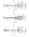
- FIG. 5 depicts a coaxial expanding tip sheath 69 designed for use with a standard laser optical fiber 3 (not shown).
- the coaxial expanding tip sheath is comprised of a coaxial sleeve 71, and a deployment fitting assembly 73.
- a through lumen 99 extends longitudinally through the sheath 69.
- the coaxial sleeve 71 consists of an outer sleeve or tube 75 and inner sleeve or tube 77 permanently connected at the distal end by an outer/inner sleeve fuse section 79. Standard welding / melting methods may be used to permanently fuse the two sleeves together at the fuse section 79. The two sleeves are slideable relative to each other, except at the fuse section 79.
- the fitting is comprised of a distal fitting component 81 and a proximal fitting component 83.
- the two components are slidably connected with each other.
- the distal fitting component 81 is in coaxial arrangement with the proximal fitting component 83, allowing for longitudinal movement between the two components relative to each other.
- Gripping surface 101 of distal fitting component 81 may be used to facilitate longitudinal movement between the two components.
- Both deployment fittings 81 and 83 include a through lumen 99, through which the optical fiber 3 (not shown) may be inserted.
- the outer sleeve 75 of the coaxial sleeve 71 is securely attached to the distal fitting component 81 at connection point 95.
- the inner sleeve 77 of coaxial sleeve 71 is securely attached to the proximal fitting component 83 at connection point 97.
- Proximal fitting component 83 includes a standard female luer connector 93 that is connectable to the male luer fiber connector 103 shown in FIG. 8 and described in more detail below.
- the proximal fitting component 83 includes a longitudinally positioned multiple detent slot 87, as shown in FIG. 5 and FIG. 7 .
- a pin 85 attached to the distal fitting component 81 slides longitudinally within the detent slot 87 of the proximal fitting component 83.
- FIG. 5 shows the coaxial expanding tip sheath 69 with the deployment fitting assembly 73 in the undeployed position, as indicated by the position of pin 85.
- pin 85 is in the proximal detent position 91, the sheath 69 is in an undeployed configuration.
- the distal fitting component 81 is gripped along gripping surface 101 and pushed distally while holding the proximal fitting component 83 stationary.
- the longitudinal forward movement of the distal fitting component 81 causes pin 85 to move within slot 87 from proximal detent position 91 to distal detent position 89, as depicted in FIG. 7 .
- This movement also causes the outer sleeve 75 to slide distally since it is securely attached to the distal fitting component 81 at bond 95.
- the inner sleeve 77 does not move as it is securely attached to the stationary proximal fitting component 83 at bond 97.
- the combined movement of the outer sleeve 75 and the fixed position of the inner sleeve 77 cause the ribs 19 to expand radially outward into a deployed position as shown in FIG. 7 .
- the intermediate detent positions in slot 87 may be used to control the extent of expansion of the spacer element 19. This feature allows varying diameter veins to be treated with the same device. For example, positioning the pin 85 as described above to the detent position just distal of detent position 91 will expand the rib elements 19 only slightly. Positioning the pin 85 in more distal detent positions will cause further expansion of the rib elements 19. The ribs 19 are at the maximum expanded state when the pin is in detent position 89.
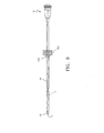
- FIG. 8 depicts an optical fiber assembly modified for use with the coaxial expanding tip sheath embodiment of FIG. 5 to FIG. 7 .
- This optical fiber embodiment was previously disclosed in US 2004/0116912, filed December 11, 2002 entitled “Endovascular Laser Treatment Device”.
- the optical fiber assembly of FIG. 8 comprises an optical fiber 13, 15, a standard SMA connector 9 for connection to a laser generator (not shown), and a male luer fiber connector 103 bonded to the optical fiber 3 at connector/fiber bond point 105.
- Approximately 2 - 4 mm of the optical fiber 3 distal end is bare fiber 13 with cladding.
- Fiber optic tip is identified as 11.
- the male luer connector 103 includes a through-hole through which the fiber 3 passes and through which the fiber 3 is bonded to the connector 103 at bond point 105.
- FIGS. 9 and 10 illustrate the coaxial expanding tip sheath embodiment coupled to an optical fiber of FIG. 8 in an undeployed configuration.
- the fiber 3 can be inserted and positioned as shown in FIG. 9 prior to insertion of the device or after the coaxial expanding tip sheath 69 has been placed within the vein.
- the distal tip 11 of the fiber is inserted and advanced through common lumen 99 ( FIG. 6 ) of the proximal fitting component 83, distal fitting component 81 lumen 99 and inner sleeve lumen, and the two luer connectors are locked with each other to securely attach the fiber 3 to the sheath 69.
- the outer tube 75 is positioned within the blood vessel 115 as shown in FIGS. 12A and 12B .
- the spacer ribs 19 are in the deployed state within the vessel 115, the expanded spacer ribs 19 position the fiber tip 11 away from the inner wall of the vessel as shown in FIGS. 13A and 13B .
- the spacer ribs 19 do not have to be centered within the vessel lumen.
- the spacer ribs 19 can be deployed such that only some of the ribs contact the inner vessel wall and still provide sufficient space to prevent the fiber tip 11 from directly contacting the vessel wall.
- the expanding tip sheath 69 embodiment is advantageous in several respects.
- the single device functions as both an introducer sheath and a spacer device for the fiber tip.
- the size of the overall device is smaller in diameter than if separate components were used in the procedure. Accordingly, the size of the access puncture is smaller and less traumatic to the patient.
- the expanding tip sheath 69 is independent of the optical fiber 3 allowing separate placement and withdrawal of the fiber, if desired.
- This embodiment also allows the introduction of diagnostic and interventional devices and fluids through the sheath lumen 99.
- the sheath 69 can be optionally inserted directly over a standard guidewire as part of the placement and positioning step. Saline or other procedural fluids can be introduced through the sheath lumen 99 into the vein.
- the fitting assembly 73 provides the user with an easy, simple means for deploying the spacer element 19 while maintaining the position of the fiber tip 11 stationary within the vein. When deployed, the spacer element 19 creates a barrier between the fiber tip 11 and the inner vein wall whereby minimizing unequal laser energy distribution.
- FIG. 14 is a schematic of an expanding spacer 109 within a retractable sleeve 107 which has been placed into a vein 115.
- the expanding spacer 109 is comprised of a plurality of spacer ribs 111, or more particularly spacer legs, which are attached to the outer wall of the optical fiber 3 by a circumferential ring 113.
- Standard bonding or welding techniques well known in the art can be used to 113.
- Standard bonding or welding techniques well known in the art can be used to affix the circumferential ring 113 to the optical fiber 3 and spacer legs 111.
- the spacer legs 111 and the circumferential ring 113 can be fabricated as a single unit and then attached to the optical fiber 3.
- the spacer legs 111 are pre-curved and preferably made of nitinol or other shape memory type material such as stainless steel or a polymer material.
- the expanding spacer 109 is formed of three to six legs 111 although other configurations are possible.
- the retractable sleeve 107 retains the plurality of legs 111 within their unexpanded and undeployed position around the optical fiber 3. At the distal end of the device, the fiber tip 11 extends beyond the spacer legs 111 by 1 - 3 cm.
- the retractable sleeve 107 is withdrawn while holding the fiber 3 stationary. Any of the previously described deployment configurations can be used to perform the retraction function. Withdrawing the retractable sleeve 107 exposes the spacer legs 111. Due to the shape-memory characteristics of the spacer legs 111, withdrawal of the sleeve 107 causes the spacer legs 111 to expand radially outward to contact the inner vessel wall 115, as shown in FIG. 15 . The expanded spacer legs 111 form a cage over the distal end of the device, ensuring that the exposed fiber tip 11 and bare fiber section 13 remain out of contact with the inner wall of the vessel lumen. Similar to the deployed ribs 19 as shown in FIGS.
- the spacer legs 111 can be deployed such that only some of the legs contact the inner vessel wall and still provide sufficient space to prevent the fiber tip 11 from directly contacting the vessel wall.
- the amount of radial expansion of the spacer legs 111 can be controlled to accommodate various sizes of the vessels.
- FIG. 16 depicts the balloon 117 assembly in a deflated state within the vein segment 115.
- the balloon 117 is attached to the fiber 3 at distal bond point 123 and to the outer shaft 119 at proximal bond point 125.
- the shaft or tube 119 forms a coaxial lumen providing for a balloon inflation/deflation lumen 121.
- the shaft 119 may be a multi-lumen tube with distinct lumens for the fiber 3 and for the balloon inflation/deflation lumen.
- the balloon may be formed from nylon, latex or other similar material well-known in the prior art.
- the shaft 119 and fiber 3 are inserted and advanced to the treatment location with the balloon 117 in a deflated position as shown in FIG. 16 .
- the balloon 117 Prior to activating the laser generator, the balloon 117 is deployed by injecting saline or other fluid through the inflation/deflation lumen 121 into the balloon 117. As fluid fills the balloon 117, it expands to prevent the fiber tip 11 from contacting the inner vessel wall 115 as shown in FIG. 17 .
- the deployed balloon maintains the position of the fiber tip 11 within the vein lumen and away from the vessel wall.
- the balloon is switched to its undeployed deflated state by withdrawing fluid from the balloon through the inflation/deflation lumen 121 using suction or other standard deflation techniques.
- the treatment procedure begins with the standard pre-operative preparation of the patient as is well known in the laser treatment art.
- the patient's diseased venous segments are marked on the skin surface.
- ultrasound guidance is used to map the greater saphenous vein from the sapheno-femoral junction to the popliteal area.
- the greater saphenous vein is accessed using a standard Seldinger technique.
- a small gauge needle is used to puncture the skin and access the vein.
- a guide wire is advanced into the vein through the lumen of the needle. The needle is then removed leaving the guidewire in place.
- a hemostasis introducer sheath 49 (as depicted in FIG. 4A ) may be introduced into the vein over the guidewire and advanced to 1 to 2 centimeters below the sapheno-femoral junction.
- the sheath 49 includes a valve gasket 59 that provides a leak-proof seal to prevent the backflow of blood out the sheath proximal opening while simultaneously allowing the introduction of fibers, guidewires and other interventional devices into the sheath.
- the valve gasket 59 is made of elastomeric material such as a rubber or latex, as commonly found in the art.
- the gasket 59 opens to allow insertion of the optical fiber 3 and then seals around the outer sleeve shaft 17.
- the valve gasket 59 does not open in response to pressure from the distal side in order to prevent the back-flow of blood or other fluids.
- the gasket 59 also prevents air from entering the sheath through the proximal hub opening.
- An inner dilator may be coupled with the hemostasis sheath to facilitate insertion and advancement of the sheath through the vein. Position of the sheath is then verified and adjusted if necessary using ultrasound. Once correct positioning is confirmed, the guide wire and dilator, if used, are removed leaving the sheath in place.
- Procedural fluids may be flushed through the sheath lumen through the side arm stopcock assembly 61 coupled to the sheath through a sidearm port 57.
- One commonly administered fluid during an endovascular laser treatment procedure is saline which is used to flush blood from the hemostasis sheath 49 prior to or after insertion of the optical fiber 3/fitting assembly 7. Blood is often flushed from the sheath 49 to prevent the adherence of blood to the flat face tip 11 of the optical fiber 3, which can adversely affect the intensity and direction of the laser energy within the vessel.
- the sidearm stopcock assembly 61 can also be used to administer emergency drugs directly into the vein.
- the distal end of the endovascular laser treatment device 1 is inserted into and is advanced through the sheath 49 until positioned as shown in FIG. 4A .
- a temporary stop (not shown) slidably connected around the sleeve 17 which is positioned between the male luer connector 27 of the fitting assembly 7 and the sheath connector 63 ensures that the fiber tip 11 position relative to the sheath tip 51 is maintained during any user adjustments.
- the temporary stop is preferred because it ensures that the fiber tip 11 is in coaxial alignment with the sheath tip 51.
- the tissue immediately surrounding the diseased vessel segment is subjected to numerous percutaneous injections of a tumescent anesthetic agent.
- the injections typically lidocaine with or without epinephrine, are administered along the entire length of the greater saphenous vein using ultrasonic guidance and the markings previously mapped out on the skin surface.
- the tumescent injections perform several functions. The anesthesia inhibits pain caused from the application of laser energy to the vein.
- the tumescent injection also provides a barrier between the vessel and the adjacent tissue and nerve structures, which restricts the heat damage to within the vessel and prevents non-target tissue damage.
- the device 1 is placed in the deployed position in preparation for the delivery of laser energy to the vein lumen. Specifically, the temporary stop is removed and the sheath is withdrawn until the sheath connector 63 comes into contact with the male luer connector 27 of the fitting assembly 7. The two connectors 63 and 27 are threaded together to attach the sheath 49 to the fitting assembly 7. The retraction of the sheath 49 exposes the fiber tip 11 and the slit zone 21 as shown in FIG. 4B . To deploy the spacer ribs 19 that are in their undeployed state as shown in FIG.
- the user holds the fiber 3 stationary while advancing the combined fitting assembly 7 / sheath 49 as a unit.
- This action causes the outer sleeve shaft 17 to advance distally and the ribs 19 to expand radially outward against the vessel wall into their deployed state as shown in FIG. 4C .
- the positioning element 29 prevents over-expansion of the ribs by contact with the proximal chamber face 67.
- the device 1 is now in the operating position, ready to delivery laser energy to the diseased vein.
- a laser generator (not shown) is connected to the SMA connector 9 of fiber 3 and is activated.
- the combined sheath 49 / endovascular laser treatment device 1 is then slowly withdrawn as a single unit through the vein, preferably at a rate of 1- 3 millimeters per second.
- the laser energy travels down the optical fiber 3, through the tip 11 of the optical fiber 3 and into the vein lumen, where it creates hot bubbles of gas in the bloodstream.
- the gas bubbles expand to contact the vein wall, along a 360-degree circumference, thus damaging vein wall tissue, and ultimately causing collapse of the vessel.
- the laser energy should be directed forward in the bloodstream to create the bubbles of gas.
- the deployed ribs ensure that the laser energy is directed forward into the bloodstream rather than being mis-directly radially against the vessel wall. Misdirected delivery of laser energy may result in vessel wall perforations where heat is concentrated and incomplete tissue necrosis where insufficient thermal energy is delivered.
- the endovascular treatment device 1 of the present invention with a fiber tip spacer 19 avoids these problems by preventing contact between the fiber tip 13 and the vessel's inner wall as the device is withdrawn through the vessel.
- the procedure for treating the varicose vein is considered to be complete when the desired length of the greater saphenous vein has been exposed to laser energy. Normally, the laser generator is turned off when the fiber tip 11 is approximately 3 centimeters from the access site. The combined sheath 49 / endovascular laser treatment device 1 is then removed from the body as a single unit.
- the spacer element can be of various designs as long as it positions the fiber tip away from the vessel wall when the laser generator is activated.
- a non-expanding, thin, ceramic-type sleeve bonded to the fiber jacket may be used for the spacer mechanism.
- the ceramic sleeve extends over and is spaced radially away from the fiber tip to prevent vessel wall contact. Although thin, the ceramic sleeve would provide the necessary barrier between the vessel wall and fiber tip to prevent unequal laser energy delivery.
- the method of providing attachment of the fiber assembly connector and the hemostasis valve housing can be accomplished in many ways.
- the described embodiment depicts a dual thread arrangement, but methods such as snap fits or any other means for providing a secure but releasable connection could be used.
- a deployment device could be provided by a rotating sleeve (nut) and thread design where the sleeve could be rotated thereby retracting the sheath and exposing the spacer element.
- the diameter size of the optical fiber can also be modified. Although 600-micron diameter optical fibers are most commonly used in endovenous laser treatment of varicose veins, diameters as small as 200 microns, for example, can be used. With a smaller diameter optical fiber, the outer sleeve provides not only the functions previously identified above, but also an increase in overall durability of the device. Specifically, the coaxially mounted sleeve provides added protection and strength to the optical fiber.
Landscapes
- Health & Medical Sciences (AREA)
- Surgery (AREA)
- Physics & Mathematics (AREA)
- Life Sciences & Earth Sciences (AREA)
- Engineering & Computer Science (AREA)
- Medical Informatics (AREA)
- Nuclear Medicine, Radiotherapy & Molecular Imaging (AREA)
- Electromagnetism (AREA)
- Optics & Photonics (AREA)
- Biomedical Technology (AREA)
- Heart & Thoracic Surgery (AREA)
- Otolaryngology (AREA)
- Molecular Biology (AREA)
- Animal Behavior & Ethology (AREA)
- General Health & Medical Sciences (AREA)
- Public Health (AREA)
- Veterinary Medicine (AREA)
- Laser Surgery Devices (AREA)
Claims (19)
- Endovaskuläres Laserbehandlungsgerät zum Kollabieren einer Vene, das aufweist:eine optische Faser (3), die dazu betreibbar ist, in eine Vene eingeführt zu werden und Laserenergie zuzuführen, um das Kollabieren der Vene zu verursachen;einen Abstandshalter (19; 109), der nahe einem distalen Ende der optischen Faser (3) angeordnet und dazu betreibbar ist, das distale Ende der optischen Faser (3) von der Innenwand der Vene weg zu positionieren, um zu verhindern, dass das distale Ende der optischen Faser (3) die Innenwand der Vene berührt, und die Laserenergie in ein Lumen der Vene und zum Blut in dem Lumen zu leiten, um ein Kollabieren der Vene zu verursachen,gekennzeichnet durch eine Hülle (49; 69), die dazu ausgelegt ist, in die Vene eingeführt zu werden, und deren distales Ende offen ist, wobei das offene Ende ein einziges distales Endloch darstellt, wobei die optische Faser (3) verschiebbar in der Hülle (49; 69) aufgenommen ist und sowohl der Abstandshalter (19; 109) als auch die optische Faser (3) dazu angeordnet sind, durch das einzige distale Endloch der Hülle (49; 69) auszutreten.
- Endovaskuläres Laserbehandlungsgerät nach Anspruch 1, wobei:der Abstandshalter (19; 109) zum Einführen in die Vene dimensioniert ist; undwenn der Abstandshalter in die Vene eingeführt ist, der Abstandshalter (19; 109) sich in einem radial aufgeweiteten entfalteten Zustand befindet, um das distale Ende der optischen Faser von der Innenwand der Vene weg zu positionieren.
- Endovaskuläres Laserbehandlungsgerät nach Anspruch 2, wobei der Abstandshalter (19; 109) nahe dem distalen Ende an der optischen Faser (3) befestigt ist.
- Endovaskuläres Laserbehandlungsgerät nach Anspruch 3, wobei der Abstandshalter eine Vielzahl von Rippen (19) aufweist, die in radialer Richtung in den entfalteten Zustand aufweitbar sind.
- Endovaskuläres Laserbehandlungsgerät nach Anspruch 3, wobei der Abstandshalter (19) ein Rohr (17) aufweist, das die optische Faser (3) umgibt, und dessen distaler Abschnitt an der optischen Faser (3) befestigt ist, wobei das Rohr (17) eine Vielzahl von Rippen (19) hat, die nahe dem distalen Abschnitt angeordnet sind, wobei die Rippen (19) in radialer Richtung in den entfalteten Zustand aufweitbar sind, wenn das Rohr (17) in Bezug zu der optischen Faser (3) bewegt wird.
- Endovaskuläres Laserbehandlungsgerät nach Anspruch 1, das des Weiteren aufweist:ein erstes Rohr (77), das dazu ausgelegt ist, die optische Faser (3) aufzunehmen; undein zweites Rohr (75), das das erste Rohr (77) umgibt, und dessen distaler Abschnitt an dem ersten Rohr (77) befestigt ist, wobei der Abstandshalter (19) nahe dem distalen Abschnitt des zweiten Rohrs (75) angeordnet und dazu betreibbar ist, das distale Ende der optischen Faser (3) von der Innenwand der Vene weg zu positionieren, wenn das zweite Rohr (75) in Bezug zu dem ersten Rohr (77) bewegt wird.
- Endovaskuläres Laserbehandlungsgerät nach Anspruch 1, wobei die Hülle (49; 69) zum Einführen in eine Vene unterhalb des Venensterns dimensioniert ist.
- Endovaskuläres Laserbehandlungsgerät nach Anspruch 1, wobei:der Abstandshalter eine Vielzahl von Rippen (19) aufweist, die in radialer Richtung in einen entfalteten Zustand aufweitbar sind; unddie Vielzahl von Rippen (19) proximale Enden haben, die an der optischen Faser (3) befestigt sind, und distale Enden, die nicht an der optischen Faser (3) befestigt sind.
- Endovaskuläres Laserbehandlungsgerät nach einem der vorhergehenden Ansprüche, wobei der Abstandshalter einen Ballon (117) aufweist, der nahe dem distalen Ende der optischen Faser (3) angeordnet ist.
- Endovaskuläres Laserbehandlungsgerät nach Anspruch 1, wobei:die optische Faser (3) einen Faseranschluss (27) hat, der in einem ausgewählten Abstand von dem distalen Ende der optischen Faser an der optischen Faser (3) befestigt ist; unddie Hülle (49) einen Hüllenanschluss (63) zum Anschluss an den Faseranschluss (27) hat, so dass, wenn der Hüllen- und der Faseranschluss miteinander verbunden sind, das distale Ende der optischen Faser sich einen vorgegebenen Abstand von dem distalen Ende der Hülle erstreckt.
- Endovaskuläres Laserbehandlungsgerät nach einem der Ansprüche 1 bis 10, das des Weiteren eine Entfaltungsvorrichtung (7; 73) aufweist, die mit dem Abstandshalter (101) verbunden ist und eine erste Position hat, in der sich der Abstandshalter in einem nicht entfalteten Zustand befindet, und eine zweite Position, in der sich der Abstandshalter in einem entfalteten Zustand befindet.
- Endovaskuläres Laserbehandlungsgerät nach Anspruch 11, wobei die Entfaltungsvorrichtung (7; 73) eine oder mehrere Zwischenpositionen zwischen der ersten und der zweiten Position hat, um den Abstand zwischen dem distalen Ende der optischen Faser (3) und der Innenwand der Vene zu verändern.
- Endovaskuläres Laserbehandlungsgerät nach Anspruch 11, wobei die Entfaltungsvorrichtung (7; 73) kontinuierliche Positionsveränderung zwischen der ersten Position und der zweiten Position vorsieht.
- Endovaskuläres Laserbehandlungsgerät nach Anspruch 1, wobei:der Abstandshalter (109) eine Vielzahl vorgebogener Rippen (111) aufweist, die aus Formgedächtnismaterial hergestellt sind, und die in radialer Richtung in einen entfalteten Zustand aufweitbar sind; unddie Vielzahl von Rippen (111) proximale Enden hat, die an der optischen Faser (3) befestigt sind, und distale Enden, die nicht an der optischen Faser (3) befestigt sind.
- Endovaskuläres Laserbehandlungsgerät nach Anspruch 14, wobei die Rippen (111) aus Nitinol-Formgedächtnismaterial hergestellt sind.
- Endovaskuläres Laserbehandlungsgerät nach Anspruch 1, wobei der Abstandshalter nahe dem distalen Ende der optischen Faser an der optischen Faser (3) befestigt ist, wobei die optische Faser an ihrem distalen Ende eine Spitze definiert, und wobei der Abstandshalter eine sich nicht aufweitende Hülle ist, die sich über die Faserspitze erstreckt und radial davon beabstandet ist.
- Endovaskuläres Laserbehandlungsgerät nach Anspruch 16, wobei der Abstandshalter eine nicht aufweitende Hülle vom Keramiktyp ist.
- Endovaskuläres Laserbehandlungsgerät nach Anspruch 16, wobei die Rippen aus Formgedächtnismaterial hergestellt sind.
- Endovaskuläres Laserbehandlungsgerät nach einem der vorhergehenden Ansprüche, wobei sich die optische Faser (3) 1 - 3 cm distal von dem Abstandshalter (19, 109, 117) erstreckt.
Applications Claiming Priority (3)
| Application Number | Priority Date | Filing Date | Title |
|---|---|---|---|
| US39521802P | 2002-07-10 | 2002-07-10 | |
| US395218P | 2002-07-10 | ||
| PCT/US2003/021213 WO2004004546A2 (en) | 2002-07-10 | 2003-07-03 | Endovascular laser treatment device having a fiber tip spacer |
Publications (3)
| Publication Number | Publication Date |
|---|---|
| EP1539012A2 EP1539012A2 (de) | 2005-06-15 |
| EP1539012A4 EP1539012A4 (de) | 2010-03-10 |
| EP1539012B1 true EP1539012B1 (de) | 2014-11-19 |
Family
ID=30115837
Family Applications (1)
| Application Number | Title | Priority Date | Filing Date |
|---|---|---|---|
| EP03763292.4A Expired - Lifetime EP1539012B1 (de) | 2002-07-10 | 2003-07-03 | ENDOVASKULûRE BEHANDLUNGSVORRICHTUNG MIT FASERSPITZEN-ABSTANDSELEMENT |
Country Status (5)
| Country | Link |
|---|---|
| US (5) | US7273478B2 (de) |
| EP (1) | EP1539012B1 (de) |
| AU (1) | AU2003261120A1 (de) |
| ES (1) | ES2527051T3 (de) |
| WO (1) | WO2004004546A2 (de) |
Families Citing this family (80)
| Publication number | Priority date | Publication date | Assignee | Title |
|---|---|---|---|---|
| AU6146798A (en) | 1997-03-04 | 1998-09-22 | Vnus Medical Technologies, Inc. | Method and apparatus for treating venous insufficiency using directionally applied energy |
| EP2134282B1 (de) | 2002-07-10 | 2019-05-22 | AngioDynamics, Inc. | Vorrichtung zur endovaskulären behandlung zum verschluss eines blutgefässes |
| AU2003261120A1 (en) * | 2002-07-10 | 2004-01-23 | Angiodynamics, Inc. | Endovascular laser treatment device having a fiber tip spacer |
| US7033347B2 (en) * | 2002-12-11 | 2006-04-25 | Angiodynamics, Inc. | Endovascular laser treatment device |
| US20080208180A1 (en) * | 2002-07-10 | 2008-08-28 | Cartier William A | Endovascular treatment sheath having a heat insulative tip and method for using the same |
| US7644715B2 (en) | 2002-10-31 | 2010-01-12 | Cooltouch, Incorporated | Restless leg syndrome treatment |
| US20040092913A1 (en) * | 2002-10-31 | 2004-05-13 | Hennings David R. | Endovenous closure of varicose veins with mid infrared laser |
| US7524316B2 (en) * | 2002-10-31 | 2009-04-28 | Cooltouch, Inc. | Endovenous closure of varicose veins with mid infrared laser |
| US7921854B2 (en) * | 2002-10-31 | 2011-04-12 | Cooltouch Incorporated | Endovenous laser treatment for varicose veins |
| US8409183B2 (en) | 2003-10-30 | 2013-04-02 | Cooltouch Incorporated | Endovenous laser treatment generating reduced blood coagulation |
| US20080021527A1 (en) * | 2003-10-30 | 2008-01-24 | Cooltouch Incorporated | Endovenous laser treatment generating reduced blood coagulation |
| US20050256553A1 (en) * | 2004-02-09 | 2005-11-17 | John Strisower | Method and apparatus for the treatment of respiratory and other infections using ultraviolet germicidal irradiation |
| US20070179486A1 (en) * | 2004-06-29 | 2007-08-02 | Jeff Welch | Laser fiber for endovenous therapy having a shielded distal tip |
| US20050288655A1 (en) * | 2004-06-29 | 2005-12-29 | Howard Root | Laser fiber for endovenous therapy having a shielded distal tip |
| WO2006031541A1 (en) * | 2004-09-09 | 2006-03-23 | Vnus Medical Technologies, Inc. | Methods and apparatus for treatment of hollow anatomical structures |
| DE102005017204B4 (de) * | 2005-04-14 | 2012-03-22 | Lisa Laser Products Ohg Fuhrberg & Teichmann | Endoskop und Verfahren zum Einführen einer Lichtleitfaser in einen Arbeitskanal eines Endoskops |
| SE0501077L (sv) * | 2005-05-12 | 2006-11-13 | Spectracure Ab | Anordning för fotodynamisk diagnos eller behandling |
| US7500974B2 (en) * | 2005-06-28 | 2009-03-10 | Covidien Ag | Electrode with rotatably deployable sheath |
| US20070073278A1 (en) * | 2005-09-16 | 2007-03-29 | Johnson Kevin C | Cardiac Ablation Dosing |
| US20070299431A1 (en) * | 2006-05-02 | 2007-12-27 | Green Medical, Inc. | Systems and methods for treating superficial venous malformations like spider veins |
| US7465312B2 (en) | 2006-05-02 | 2008-12-16 | Green Medical, Inc. | Systems and methods for treating superficial venous malformations like spider veins |
| US9028520B2 (en) | 2006-12-22 | 2015-05-12 | The Spectranetics Corporation | Tissue separating systems and methods |
| US8961551B2 (en) | 2006-12-22 | 2015-02-24 | The Spectranetics Corporation | Retractable separating systems and methods |
| EP2150194B1 (de) | 2007-04-27 | 2012-09-12 | Tyco Healthcare Group LP | System zur behandlung hohler anatomischer strukturen |
| US20080300662A1 (en) * | 2007-06-01 | 2008-12-04 | Spectranetics | Custom Laser Sequences |
| US20080300583A1 (en) * | 2007-06-01 | 2008-12-04 | Ceramoptec Industries, Inc. | Vascular laser treatment device and method |
| US8298215B2 (en) * | 2007-09-25 | 2012-10-30 | Vascular Solutions, Inc. | Guidewire tipped laser fiber |
| US20090171332A1 (en) * | 2007-12-27 | 2009-07-02 | Intuitive Surgical, Inc. | Medical device with orientable tip for robotically directed laser cutting and biomaterial application |
| US10085802B2 (en) * | 2008-02-28 | 2018-10-02 | Biolitec Unternehmensbeteiligungs Ii Ag | Endoluminal laser ablation device and method for treating veins |
| US9770297B2 (en) | 2008-06-04 | 2017-09-26 | Covidien Lp | Energy devices and methods for treating hollow anatomical structures |
| WO2010054456A1 (en) * | 2008-11-14 | 2010-05-20 | Wagner Paula Ferreira | Catheter for endoluminal laser with centralizer and apical sensors of temperature |
| NL2002597C2 (en) | 2009-03-06 | 2010-09-07 | Tobrix B V | Endovascular treatment device, system for endovascular treatment and method of operating |
| EP2229980B1 (de) * | 2009-03-16 | 2015-08-12 | Nuvolase, Inc. | Behandlung mikrobiologischer Krankheitserreger in einem Zehennagel mit antimikrobiellem Licht |
| US8814922B2 (en) * | 2009-07-22 | 2014-08-26 | New Star Lasers, Inc. | Method for treatment of fingernail and toenail microbial infections using infrared laser heating and low pressure |
| CA2862611C (en) | 2011-02-24 | 2020-11-03 | Eximo Medical Ltd. | Hybrid catheter for tissue resection |
| US10434292B2 (en) * | 2011-06-24 | 2019-10-08 | Access Closure | Method and devices for flow occlusion during device exchanges |
| US8992513B2 (en) | 2011-06-30 | 2015-03-31 | Angiodynamics, Inc | Endovascular plasma treatment device and method of use |
| WO2013119662A1 (en) * | 2012-02-06 | 2013-08-15 | Cornell University | Catheter based system and method for thrombus removal using time reversal acoustics |
| US20150112319A1 (en) * | 2012-03-06 | 2015-04-23 | Intermedic Arfran, S.A. | Bidirectional self-centering tip for fiber optics designed for endovascular treatments |
| US9763692B2 (en) | 2012-09-14 | 2017-09-19 | The Spectranetics Corporation | Tissue slitting methods and systems |
| US12514456B2 (en) | 2013-01-31 | 2026-01-06 | Eximo Medical Ltd. | System and methods for lesion characterization in blood vessels |
| US9283040B2 (en) | 2013-03-13 | 2016-03-15 | The Spectranetics Corporation | Device and method of ablative cutting with helical tip |
| US9291663B2 (en) | 2013-03-13 | 2016-03-22 | The Spectranetics Corporation | Alarm for lead insulation abnormality |
| US9456872B2 (en) | 2013-03-13 | 2016-10-04 | The Spectranetics Corporation | Laser ablation catheter |
| US10383691B2 (en) | 2013-03-13 | 2019-08-20 | The Spectranetics Corporation | Last catheter with helical internal lumen |
| US9883885B2 (en) | 2013-03-13 | 2018-02-06 | The Spectranetics Corporation | System and method of ablative cutting and pulsed vacuum aspiration |
| US10835279B2 (en) | 2013-03-14 | 2020-11-17 | Spectranetics Llc | Distal end supported tissue slitting apparatus |
| US9668765B2 (en) | 2013-03-15 | 2017-06-06 | The Spectranetics Corporation | Retractable blade for lead removal device |
| EP3341071B1 (de) | 2013-03-15 | 2020-01-29 | The Spectranetics Corporation | Medizinische vorrichtung zur entfernung eines implantierten objekts mittels lasergeschnittenen hypotubes |
| US9918737B2 (en) | 2013-03-15 | 2018-03-20 | The Spectranetics Corporation | Medical device for removing an implanted object |
| US10842532B2 (en) | 2013-03-15 | 2020-11-24 | Spectranetics Llc | Medical device for removing an implanted object |
| US10448999B2 (en) | 2013-03-15 | 2019-10-22 | The Spectranetics Corporation | Surgical instrument for removing an implanted object |
| WO2014151814A1 (en) | 2013-03-15 | 2014-09-25 | The Spectranetics Corporation | Surgical instrument for removing an implanted object |
| US9827438B2 (en) | 2013-07-03 | 2017-11-28 | Uvlrx Therapeutics, Inc. | Vascular access device with integrated light guide |
| ES2696273T3 (es) | 2013-10-21 | 2019-01-14 | Bone Salat Carlos | Dispositivo para el tratamiento de varices tronculares y/o colaterales |
| US12053203B2 (en) | 2014-03-03 | 2024-08-06 | Spectranetics, Llc | Multiple configuration surgical cutting device |
| EP3113701B1 (de) | 2014-03-03 | 2020-07-22 | The Spectranetics Corporation | Chirurgische schneidevorrichtung mit mehrfachkonfiguration |
| US10405924B2 (en) | 2014-05-30 | 2019-09-10 | The Spectranetics Corporation | System and method of ablative cutting and vacuum aspiration through primary orifice and auxiliary side port |
| US20160030023A1 (en) * | 2014-07-31 | 2016-02-04 | Terumo Kabushiki Kaisha | Method for treating varicose veins and intraluminal device used in such method |
| KR101510133B1 (ko) * | 2014-11-18 | 2015-04-09 | (주)휴레이저 | 광섬유의 길이를 조절할 수 있는 핸드피스 레이저 치료장치 |
| USD770616S1 (en) | 2015-02-20 | 2016-11-01 | The Spectranetics Corporation | Medical device handle |
| USD765243S1 (en) | 2015-02-20 | 2016-08-30 | The Spectranetics Corporation | Medical device handle |
| US10092356B2 (en) | 2015-11-18 | 2018-10-09 | InnovaQuartz LLC | Radial emissions from optical fibers |
| US11826097B2 (en) | 2015-11-18 | 2023-11-28 | Cyclone Biosciences, Llc | Forming radial emissions from optical fibers |
| US9618700B1 (en) | 2015-12-03 | 2017-04-11 | InnovaQuartz LLC | Orthogonal output optical fiber |
| US9662173B1 (en) | 2015-12-24 | 2017-05-30 | Cyclone Biosciences LLC | Lateral delivery device with active cooling |
| CN105662579B (zh) * | 2016-03-08 | 2018-08-28 | 四川航天世都制导有限公司 | 一种新型激光治疗手柄 |
| US11684420B2 (en) | 2016-05-05 | 2023-06-27 | Eximo Medical Ltd. | Apparatus and methods for resecting and/or ablating an undesired tissue |
| US11191976B2 (en) * | 2017-05-19 | 2021-12-07 | Prometheus Therapeutics Inc. | Devices and methods for repair of a selected blood vessel or part thereof and rapid healing of injured internal body cavity walls |
| JP2019014679A (ja) | 2017-07-07 | 2019-01-31 | ロレアル | 超微細o/wエマルションの形態のケラチン繊維のためのシリコーン非含有組成物 |
| WO2020019305A1 (zh) * | 2018-07-27 | 2020-01-30 | 尚华 | 一种能够光纤穿刺的光动力治疗诊断装置 |
| US11253318B2 (en) | 2018-08-21 | 2022-02-22 | Optical Integrity, Inc. | Arrangement for filtering out damaging heat created from laser energy contacting a kidney stone |
| CN112955798B (zh) * | 2018-08-31 | 2022-08-05 | 赛纳吉亚医疗公司 | 用于光电子有源植入式医疗设备(aimd)的光纤连接器 |
| DE112020004689T5 (de) * | 2019-09-30 | 2022-06-15 | North Star Medical Inc. | Hülse oder katheter mit dilatator zur visualisierung der transseptalen punktion und perforation und methode zur verwendung davon |
| US10980523B1 (en) * | 2019-11-01 | 2021-04-20 | Stephanie Toy | Medical device to access pericardial space with control |
| CN115460999A (zh) | 2020-03-04 | 2022-12-09 | 施菲姆德控股有限责任公司 | 血栓去除系统及相关方法 |
| US12376904B1 (en) | 2020-09-08 | 2025-08-05 | Angiodynamics, Inc. | Dynamic laser stabilization and calibration system |
| EP4322877B1 (de) * | 2021-04-13 | 2026-03-25 | Nanospectra Biosciences, Inc. | System für ablationstherapie |
| CN113499088B (zh) * | 2021-06-08 | 2022-05-06 | 郭宏波 | 一种下肢静脉曲张可视化腔内闭合系统 |
| US12038322B2 (en) | 2022-06-21 | 2024-07-16 | Eximo Medical Ltd. | Devices and methods for testing ablation systems |
Family Cites Families (46)
| Publication number | Priority date | Publication date | Assignee | Title |
|---|---|---|---|---|
| US4564011A (en) | 1982-03-22 | 1986-01-14 | Leon Goldman | Laser optic device and method |
| US4773413A (en) | 1983-06-13 | 1988-09-27 | Trimedyne Laser Systems, Inc. | Localized heat applying medical device |
| US4627436A (en) * | 1984-03-01 | 1986-12-09 | Innoventions Biomedical Inc. | Angioplasty catheter and method for use thereof |
| US4817601A (en) * | 1985-03-06 | 1989-04-04 | C. R. Bard, Inc. | Catheter system for controlled removal by radiant energy of biological obstructions |
| US5693043A (en) * | 1985-03-22 | 1997-12-02 | Massachusetts Institute Of Technology | Catheter for laser angiosurgery |
| DE3718139C1 (de) * | 1987-05-29 | 1988-12-08 | Strahlen Umweltforsch Gmbh | Herzkatheter |
| EP0311295A3 (de) | 1987-10-07 | 1990-02-28 | University College London | Chirurgische Apparate |
| DE3803697A1 (de) * | 1988-02-08 | 1989-08-17 | Wolfgang Arno Karl Dr Radtke | Laser - valvotomie - katheter (herzkatheter zur perkutanen gezielten valvotomie verengter herzklappen) |
| US5030201A (en) | 1989-11-24 | 1991-07-09 | Aubrey Palestrant | Expandable atherectomy catheter device |
| US5897551A (en) * | 1990-03-23 | 1999-04-27 | Myriadlase, Inc. | Medical device for applying high energy light and heat for gynecological sterilization procedures |
| US5154708A (en) * | 1990-05-15 | 1992-10-13 | Surgical Laser Technologies, Inc. | Unitary scalpel for contact laser surgery |
| US5484384A (en) * | 1991-01-29 | 1996-01-16 | Med Institute, Inc. | Minimally invasive medical device for providing a radiation treatment |
| US5156151A (en) * | 1991-02-15 | 1992-10-20 | Cardiac Pathways Corporation | Endocardial mapping and ablation system and catheter probe |
| JPH05506601A (ja) * | 1991-02-19 | 1993-09-30 | アドバンスト インターベンショナル システムズ,インコーポレイテッド | 高エネルギーパルスレーザ光のガイド及び伝送システム |
| US5151096A (en) | 1991-03-28 | 1992-09-29 | Angiolaz, Incorporated | Laser catheter diffuser |
| US5239999A (en) * | 1992-03-27 | 1993-08-31 | Cardiac Pathways Corporation | Helical endocardial catheter probe |
| US5324284A (en) * | 1992-06-05 | 1994-06-28 | Cardiac Pathways, Inc. | Endocardial mapping and ablation system utilizing a separately controlled ablation catheter and method |
| US5807306A (en) * | 1992-11-09 | 1998-09-15 | Cortrak Medical, Inc. | Polymer matrix drug delivery apparatus |
| US5476495A (en) * | 1993-03-16 | 1995-12-19 | Ep Technologies, Inc. | Cardiac mapping and ablation systems |
| US5403311A (en) * | 1993-03-29 | 1995-04-04 | Boston Scientific Corporation | Electro-coagulation and ablation and other electrotherapeutic treatments of body tissue |
| US5445608A (en) * | 1993-08-16 | 1995-08-29 | James C. Chen | Method and apparatus for providing light-activated therapy |
| US5431168A (en) * | 1993-08-23 | 1995-07-11 | Cordis-Webster, Inc. | Steerable open-lumen catheter |
| US5582609A (en) * | 1993-10-14 | 1996-12-10 | Ep Technologies, Inc. | Systems and methods for forming large lesions in body tissue using curvilinear electrode elements |
| US5507743A (en) * | 1993-11-08 | 1996-04-16 | Zomed International | Coiled RF electrode treatment apparatus |
| US5437664A (en) * | 1994-01-18 | 1995-08-01 | Endovascular, Inc. | Apparatus and method for venous ligation |
| US5573531A (en) * | 1994-06-20 | 1996-11-12 | Gregory; Kenton W. | Fluid core laser angioscope |
| US5617854A (en) * | 1994-06-22 | 1997-04-08 | Munsif; Anand | Shaped catheter device and method |
| US5593405A (en) * | 1994-07-16 | 1997-01-14 | Osypka; Peter | Fiber optic endoscope |
| DE4425195C1 (de) * | 1994-07-16 | 1995-11-16 | Osypka Peter | Katheter mit Mehrfachelektrode |
| US5643253A (en) * | 1995-06-06 | 1997-07-01 | Rare Earth Medical, Inc. | Phototherapy apparatus with integral stopper device |
| US5836940A (en) * | 1994-10-25 | 1998-11-17 | Latis, Inc. | Photoacoustic drug delivery |
| US5895398A (en) * | 1996-02-02 | 1999-04-20 | The Regents Of The University Of California | Method of using a clot capture coil |
| AU733465B2 (en) * | 1996-03-05 | 2001-05-17 | Tyco Healthcare Group, Lp | Vascular catheter-based system for heating tissue |
| US5725521A (en) * | 1996-03-29 | 1998-03-10 | Eclipse Surgical Technologies, Inc. | Depth stop apparatus and method for laser-assisted transmyocardial revascularization and other surgical applications |
| US6024740A (en) * | 1997-07-08 | 2000-02-15 | The Regents Of The University Of California | Circumferential ablation device assembly |
| US6012457A (en) * | 1997-07-08 | 2000-01-11 | The Regents Of The University Of California | Device and method for forming a circumferential conduction block in a pulmonary vein |
| US5928260A (en) * | 1997-07-10 | 1999-07-27 | Scimed Life Systems, Inc. | Removable occlusion system for aneurysm neck |
| US6258084B1 (en) | 1997-09-11 | 2001-07-10 | Vnus Medical Technologies, Inc. | Method for applying energy to biological tissue including the use of tumescent tissue compression |
| US6200312B1 (en) | 1997-09-11 | 2001-03-13 | Vnus Medical Technologies, Inc. | Expandable vein ligator catheter having multiple electrode leads |
| US6561998B1 (en) * | 1998-04-07 | 2003-05-13 | Transvascular, Inc. | Transluminal devices, systems and methods for enlarging interstitial penetration tracts |
| US6398777B1 (en) | 1999-02-01 | 2002-06-04 | Luis Navarro | Endovascular laser device and treatment of varicose veins |
| US6263236B1 (en) * | 1999-11-29 | 2001-07-17 | Illumenex Corporation | Non-occlusive expandable catheter |
| US6582400B1 (en) * | 2000-10-24 | 2003-06-24 | Scimed Life Systems, Inc. | Variable tip catheter |
| US6986766B2 (en) * | 2001-06-15 | 2006-01-17 | Diomed Inc. | Method of endovenous laser treatment |
| AU2003261120A1 (en) * | 2002-07-10 | 2004-01-23 | Angiodynamics, Inc. | Endovascular laser treatment device having a fiber tip spacer |
| US7524316B2 (en) * | 2002-10-31 | 2009-04-28 | Cooltouch, Inc. | Endovenous closure of varicose veins with mid infrared laser |
-
2003
- 2003-07-03 AU AU2003261120A patent/AU2003261120A1/en not_active Abandoned
- 2003-07-03 ES ES03763292.4T patent/ES2527051T3/es not_active Expired - Lifetime
- 2003-07-03 WO PCT/US2003/021213 patent/WO2004004546A2/en not_active Ceased
- 2003-07-03 EP EP03763292.4A patent/EP1539012B1/de not_active Expired - Lifetime
- 2003-07-03 US US10/613,395 patent/US7273478B2/en not_active Expired - Lifetime
-
2007
- 2007-07-12 US US11/777,198 patent/US7559329B2/en not_active Expired - Lifetime
-
2009
- 2009-07-01 US US12/496,515 patent/US8425501B2/en not_active Expired - Fee Related
-
2013
- 2013-03-26 US US13/850,932 patent/US8840606B2/en not_active Expired - Lifetime
-
2014
- 2014-08-21 US US14/465,490 patent/US20140358134A1/en not_active Abandoned
Also Published As
| Publication number | Publication date |
|---|---|
| EP1539012A2 (de) | 2005-06-15 |
| US20080015559A1 (en) | 2008-01-17 |
| US8840606B2 (en) | 2014-09-23 |
| WO2004004546A3 (en) | 2004-05-13 |
| US20130261614A1 (en) | 2013-10-03 |
| ES2527051T3 (es) | 2015-01-20 |
| US7273478B2 (en) | 2007-09-25 |
| US20040010248A1 (en) | 2004-01-15 |
| US20090264875A1 (en) | 2009-10-22 |
| AU2003261120A8 (en) | 2004-01-23 |
| US7559329B2 (en) | 2009-07-14 |
| WO2004004546A2 (en) | 2004-01-15 |
| US20140358134A1 (en) | 2014-12-04 |
| AU2003261120A1 (en) | 2004-01-23 |
| EP1539012A4 (de) | 2010-03-10 |
| US8425501B2 (en) | 2013-04-23 |
Similar Documents
| Publication | Publication Date | Title |
|---|---|---|
| EP1539012B1 (de) | ENDOVASKULûRE BEHANDLUNGSVORRICHTUNG MIT FASERSPITZEN-ABSTANDSELEMENT | |
| US20030236517A1 (en) | Endovascular treatment device with a protective sleeve | |
| US11589854B2 (en) | Apparatus and methods to create and maintain an intra-atrial pressure relief opening | |
| US10292690B2 (en) | Apparatus and methods to create and maintain an intra-atrial pressure relief opening | |
| US8413664B2 (en) | Method of thermally treating blood vessels | |
| EP4458303B1 (de) | Endoluminale laserablationsvorrichtung zur behandlung von venen | |
| US10085802B2 (en) | Endoluminal laser ablation device and method for treating veins | |
| US20150057648A1 (en) | Laser Device and Method of Use | |
| US20080208180A1 (en) | Endovascular treatment sheath having a heat insulative tip and method for using the same | |
| US20250255593A1 (en) | Apparatus and methods to create and maintain an intra-atrial pressure relief opening | |
| WO2026035576A1 (en) | Pleatless delivery intravascular lithotripsy system |
Legal Events
| Date | Code | Title | Description |
|---|---|---|---|
| PUAI | Public reference made under article 153(3) epc to a published international application that has entered the european phase |
Free format text: ORIGINAL CODE: 0009012 |
|
| 17P | Request for examination filed |
Effective date: 20050208 |
|
| AK | Designated contracting states |
Kind code of ref document: A2 Designated state(s): AT BE BG CH CY CZ DE DK EE ES FI FR GB GR HU IE IT LI LU MC NL PT RO SE SI SK TR |
|
| AX | Request for extension of the european patent |
Extension state: AL LT LV MK |
|
| DAX | Request for extension of the european patent (deleted) | ||
| RBV | Designated contracting states (corrected) |
Designated state(s): DE ES FR IT |
|
| A4 | Supplementary search report drawn up and despatched |
Effective date: 20100208 |
|
| 17Q | First examination report despatched |
Effective date: 20100614 |
|
| REG | Reference to a national code |
Ref country code: DE Ref legal event code: R079 Ref document number: 60347011 Country of ref document: DE Free format text: PREVIOUS MAIN CLASS: A61B0018180000 Ipc: A61B0018240000 |
|
| GRAP | Despatch of communication of intention to grant a patent |
Free format text: ORIGINAL CODE: EPIDOSNIGR1 |
|
| RIC1 | Information provided on ipc code assigned before grant |
Ipc: A61B 18/24 20060101AFI20140605BHEP |
|
| INTG | Intention to grant announced |
Effective date: 20140623 |
|
| GRAS | Grant fee paid |
Free format text: ORIGINAL CODE: EPIDOSNIGR3 |
|
| GRAA | (expected) grant |
Free format text: ORIGINAL CODE: 0009210 |
|
| AK | Designated contracting states |
Kind code of ref document: B1 Designated state(s): DE ES FR IT |
|
| REG | Reference to a national code |
Ref country code: DE Ref legal event code: R096 Ref document number: 60347011 Country of ref document: DE Effective date: 20141224 |
|
| REG | Reference to a national code |
Ref country code: ES Ref legal event code: FG2A Ref document number: 2527051 Country of ref document: ES Kind code of ref document: T3 Effective date: 20150120 |
|
| REG | Reference to a national code |
Ref country code: DE Ref legal event code: R097 Ref document number: 60347011 Country of ref document: DE |
|
| PLBE | No opposition filed within time limit |
Free format text: ORIGINAL CODE: 0009261 |
|
| STAA | Information on the status of an ep patent application or granted ep patent |
Free format text: STATUS: NO OPPOSITION FILED WITHIN TIME LIMIT |
|
| 26N | No opposition filed |
Effective date: 20150820 |
|
| REG | Reference to a national code |
Ref country code: FR Ref legal event code: PLFP Year of fee payment: 14 |
|
| REG | Reference to a national code |
Ref country code: FR Ref legal event code: PLFP Year of fee payment: 15 |
|
| REG | Reference to a national code |
Ref country code: FR Ref legal event code: PLFP Year of fee payment: 16 |
|
| PGFP | Annual fee paid to national office [announced via postgrant information from national office to epo] |
Ref country code: ES Payment date: 20200803 Year of fee payment: 18 |
|
| PGFP | Annual fee paid to national office [announced via postgrant information from national office to epo] |
Ref country code: FR Payment date: 20210611 Year of fee payment: 19 Ref country code: IT Payment date: 20210610 Year of fee payment: 19 |
|
| PGFP | Annual fee paid to national office [announced via postgrant information from national office to epo] |
Ref country code: DE Payment date: 20210608 Year of fee payment: 19 |
|
| REG | Reference to a national code |
Ref country code: ES Ref legal event code: FD2A Effective date: 20220826 |
|
| PG25 | Lapsed in a contracting state [announced via postgrant information from national office to epo] |
Ref country code: ES Free format text: LAPSE BECAUSE OF NON-PAYMENT OF DUE FEES Effective date: 20210704 |
|
| REG | Reference to a national code |
Ref country code: DE Ref legal event code: R119 Ref document number: 60347011 Country of ref document: DE |
|
| PG25 | Lapsed in a contracting state [announced via postgrant information from national office to epo] |
Ref country code: FR Free format text: LAPSE BECAUSE OF NON-PAYMENT OF DUE FEES Effective date: 20220731 |
|
| PG25 | Lapsed in a contracting state [announced via postgrant information from national office to epo] |
Ref country code: DE Free format text: LAPSE BECAUSE OF NON-PAYMENT OF DUE FEES Effective date: 20230201 |
|
| PG25 | Lapsed in a contracting state [announced via postgrant information from national office to epo] |
Ref country code: IT Free format text: LAPSE BECAUSE OF NON-PAYMENT OF DUE FEES Effective date: 20220703 |