EP1538858A1 - Systeme de communication mobile - Google Patents
Systeme de communication mobile Download PDFInfo
- Publication number
- EP1538858A1 EP1538858A1 EP02780033A EP02780033A EP1538858A1 EP 1538858 A1 EP1538858 A1 EP 1538858A1 EP 02780033 A EP02780033 A EP 02780033A EP 02780033 A EP02780033 A EP 02780033A EP 1538858 A1 EP1538858 A1 EP 1538858A1
- Authority
- EP
- European Patent Office
- Prior art keywords
- zone
- terminal
- movement
- channel
- base station
- Prior art date
- Legal status (The legal status is an assumption and is not a legal conclusion. Google has not performed a legal analysis and makes no representation as to the accuracy of the status listed.)
- Withdrawn
Links
Images


Classifications
-
- H—ELECTRICITY
- H04—ELECTRIC COMMUNICATION TECHNIQUE
- H04W—WIRELESS COMMUNICATION NETWORKS
- H04W72/00—Local resource management
- H04W72/30—Resource management for broadcast services
Definitions
- the present invention relates to a system for providing control of the execution and stoppage of broadcasting services for each zone and for controlling changes to the type of wireless channel for supplying broadcasting services, and so forth in a mobile communication system that provides broadcasting services such as broadcast and multicast services.
- a 'multicast' is a form of broadcasting for transmitting information to all contracted terminals
- a 'broadcast' is a form of broadcasting for transmitting information to all terminals irrespective of contract.
- Fig. 1 shows the constitution of broadcast services and multicast services of a conventional mobile communication network. Broadcast data and multicast data from an information distribution device 1 reaches a wireless network control device 3 via a fixed communication network 2 and a core network 2a that constitutes a switching network and is transmitted from all the base stations 4a, 4b, ... in the service area to all the mobile devices 5 in the zone via the wireless network control device 3.
- broadcasting data is transmitted unconditionally from all the base stations in the service area. Further, when the service area (referred to as cell) of the base station is converted into sectors, broadcasting data is transmitted unconditionally to the sectors. For this reason, even in a case where a terminal receiving services does not exist in the cell or sector (generally referred to as the 'zone'), transmission is performed from the base stations to an area where no terminal exists and, hence, there is the problem that wireless resources are used wastefully, the transmission power of the base station increases, and interference power increases.
- a first object of the present invention is to make it possible to use wireless resources efficiently and reduce the transmission power and interference power of the base station.
- a second object of the present invention is to perform a zone transfer in a system that uses wireless resources efficiently without problems.
- a judgment standard (whether a terminal receiving a supply of services exists or not, for example) is established for each zone and broadcast data and multicast data, and so forth, are not transmitted from the base station to zones where the standard is not fulfilled (a terminal does not exist). Accordingly, in one zone, when the standard is not fulfilled, the transmission of broadcast data and multicast data is not performed and, therefore, the wireless resources in the zone can be used efficiently.
- a network device detects the fact that the terminal receiving the supply of services exists in a region that allows services to be received from the other zone and the data is transmitted on a wireless channel from the base station of the other zone.
- a judgment standard is established for each zone and the type of wireless channel (dedicated physical channel, common physical channel, for example) is determined on the basis of the judgment result.
- the optimal wireless channel for transmitting broadcast data and multicast data can be selected in accordance with the judgment standard. Therefore, the wireless resources in the zone can be used efficiently and the transmission power and interference power of the base station can be reduced.
- a network device determines a wireless channel on the basis of this request and the data is transmitted on the wireless channel.
- the network device detects the fact that a terminal receiving the supply of services exists in a region that allows services to be received from another zone and, determines a wireless channel when the existence of terminals is detected, and transmits the data by means of the wireless channel.
- a judgment standard (whether a terminal receiving a supply of services exists or not, for example) is established for each zone and, when the standard is not fulfilled (a terminal does not exist), broadcast data and multicast data, and so forth, are not transmitted from the base station to the zone. Accordingly, in one zone, when the standard is not fulfilled, the transmission of broadcast data and multicast data is not performed. Therefore, the wireless resources in the zone can be used efficiently. For example, (1) a case where the judgment standard is the existence of terminals receiving a supply of services and (2) a case where the judgment standard is the service quality, number of services and number of terminals using the services will be described.
- Judgment standards include (1) the number of terminals receiving a supply of services, (2) the transmission power required to provide services, (3) the amount of interference produced when services are supplied, and (4) the combination of services.
- the third invention is related to intermittent reception of services in a zone transfer and appears in the forms (1) to (7) below.
- Fig. 2 is a constitutional view of a mobile communication system that implements the broadcast and multicast of the present invention and is constituted by an information distribution device 10 that distributes broadcast data or multicast data, a wireless network control device 13 that receives the broadcast data or multicast data distributed by the information distribution device via a fixed communication network 11 and a core network 12 and transmits the data to the base station on a logical channel, base stations 14 1 and 14 2 that receive broadcast data or multicast data from the wireless network control device and transmit data to the terminal on a physical channel, and a terminal 15 that receives the broadcast data or multicast data.
- the wireless network control device 13 sometimes also receives broadcast data or multicast data distributed by the information distribution device 10 from the core network 12 without the involvement of the fixed communication network 11.
- the base stations also appear with the number '14' hereinafter.
- Fig. 3 is a block constitutional view of the wireless network control device 13.
- a core network interface portion 13a receives broadcast data and multicast data from the information distribution device 11 via the core network 12 and sends the data to a data processing portion 13b.
- the data processing portion 13b maps broadcast data and multicast data that is inputted from the core network interface portion 13a and data (a terminal control signal) that is inputted from a wireless resource control portion 13c with a logical channel. Further, the data processing portion 13b fetches a data part of an interterminal control signal (control signal between terminals) that is inputted by a base station interface portion 13d and then sends the data part to the wireless resource control portion 13c. In addition, the data processing portion 13b transmits/stops transmission on the logical channel in accordance with an instruction from the wireless resource control portion 13c.
- the base station interface portion 13d transmits broadcast data and multicast data that has been sent by the data processing portion 13b, an interterminal control signal and an inter-base station control signal (control signal between base stations) that has been sent by the wireless resource control portion 13c to the base stations 14 1 and 14 2 , sends an interterminal control signal that has been sent by a base station to the data processing portion 13b and sends the inter-base-station control signal to the wireless resource control portion 13c.
- the wireless resource control portion 13c performs allocation and management, and so forth of wireless resources (the channel type, wireless channel (code in CDMA)) for communication between base stations and terminals. Further, the wireless resource control portion 13c judges the zone shift from peripheral-cell quality measurement information from the terminal and judges the transmission/stoppage of transmission of multicast (broadcast) data. In addition, the wireless resource control portion 13c performs processing to confirm the existence of terminals, processing to confirm the number of terminals, processing to calculate transmission power and processing to calculate the amount of interference.
- wireless resources the channel type, wireless channel (code in CDMA)
- the wireless resource control portion 13c judges the zone shift from peripheral-cell quality measurement information from the terminal and judges the transmission/stoppage of transmission of multicast (broadcast) data.
- the wireless resource control portion 13c performs processing to confirm the existence of terminals, processing to confirm the number of terminals, processing to calculate transmission power and processing to calculate the amount of interference.
- Fig. 4 is a block constitutional view of the base station 14.
- a wired transmission channel interface portion 14-1 sends broadcast data, multicast data and the interterminal control signal, which have been sent on a logical channel from the wireless network control device 13, to a modem portion 14-2 and sends the inter-base station control signal to a control portion 14-3. Further, the interterminal control signal inputted by the modem portion 14-2 and the inter-base station control signal inputted by the control portion 14-3 are sent to the wireless network control device 13.
- the modem portion 14-2 subjects broadcast data, multicast data and the interterminal control signal that have been sent by the wired transmission channel interface portion 14-1 to error-correction encoding processing in accordance with instructions from the control portion 14-3 and performs mapping to physical channels and modulation processing.
- the modem portion 14-2 subjects the interterminal control signal that has been sent by the terminal to demodulation and error correction in accordance with instructions from the control portion 14-3, and then inputs the processed interterminal control signal to the wired transmission channel interface portion 14-1 and inputs the control signal from the terminal to the base station to the control portion 14-3.
- the modem portion 14-2 performs transmission/transmission stoppage processing in accordance with instructions from the control portion 14-3.
- a transceiver portion and amplifier portion 14-4 receives the signal from the terminal, amplifies the signal by means of a low noise amplifier, and performs QPSK detection. Further, the modulated signal inputted from the modem portion 14-2 is rendered an RF signal and then transmitted to the terminal by means of an antenna following amplification by means of a transmission power amplifier.
- the control portion 14-3 receives the inter-base station control signal from the wired transmission channel interface portion 14-1 and then instructs the modem portion 14-2 to set the wireless resources (example: the channel type, the wireless channel (code in CDMA)). Further, the control portion 14-3 receives the inter-base station control signal from the wired transmission channel interface portion 14-1 and instructs the modem portion 14-2 to set the transmission/transmission stoppage of the physical channel.
- the control portion 14-3 receives the inter-base station control signal from the wired transmission channel interface portion 14-1 and instructs the modem portion 14-2 to set the transmission/transmission stoppage of the physical channel.
- control portion 14-3 sends and receives control signals to and from a terminal existence confirmation processing portion or terminal number confirmation processing portion 14-5, a transmission power calculation processing portion or interference amount calculation processing portion 14-6 and a data transmission/transmission stoppage judgment portion 14-7, and instructs the modem portion 14-2 to set the channel type and to set data transmission/transmission stoppage.
- the terminal existence confirmation processing portion or terminal number confirmation processing portion 14-5 performs terminal existence confirmation processing or terminal number confirmation processing in accordance with a control signal from the terminal that has been sent by the control portion 14-3 and with the wireless-resources usage status and sends the results to the control portion.
- the transmission power calculation processing portion or interference amount calculation processing portion 14-6 performs transmission power calculation processing or interference amount calculation processing in accordance with a control signal from a terminal that has been sent by the control portion 14-3 and with the wireless resources usage status and sends the results to the control portion.
- the data transmission/transmission stoppage judgment portion 14-7 performs data transmission/transmission stoppage judgment processing in accordance with the control signal from the terminal that has been sent by the control portion 14-3 and with the wireless resources usage status and sends the judgment result to the control portion.
- Fig. 5 is a block constitutional view of the terminal 15.
- a receiver portion 15a receives a signal from a base station, performs frequency conversion to render a high frequency signal a baseband signal and performs a QPSK detection.
- a demodulation portion 15b subjects the received signal to demodulation and error correction in accordance with settings from a control portion 15c, acquires broadcast data and multicast data and sends the data to a data processing portion 15d. Further, the demodulation portion 15b similarly acquires an inter-wireless network control signal (a control signal between wireless networks) and an inter-base station control signal (a control signal between base stations) that have been sent by the receiver portion and sends these signals to the control portion 15c.
- an inter-wireless network control signal a control signal between wireless networks
- an inter-base station control signal a control signal between base stations
- a reception field strength detection portion 15e detects the received signal strength (reception field strength), measures the reception power, interference power, and so forth of a reference signal (pilot signal) in the resident zone and peripheral zones, as well as the reception power, interference power, and so forth of the communication channel and sends the measurement results to the control portion 15c.
- a modulation portion 15f subjects the data sent by the data-processing portion 15d to encoding for error correction in accordance with settings from the control portion 15c and performs mapping to physical channels and modulation processing before sending the processing results to a transmission portion 15g. Further, the modulation portion 15f similarly subjects the inter-wireless network control signal and inter-base station control signal that have been inputted by the control portion 15c to encoding for error correction in accordance with settings from the control portion and performs mapping to physical channels and modulation processing before sending the processing results to the transmission portion. Further, the inter-wireless network control signal and inter-base station control signal contain the measurement results of the reception field strength detection portion 15e.
- the transmission portion 15g renders the modulated signal inputted by the modulation portion an RF signal and transmits the signal to the base station by means of an antenna after amplifying the signal by means of a transmission power amplifier.
- the data-processing portion 15d processes the broadcast data and multicast data that have been sent by the demodulation portion 15b in accordance with the data type, sends the processed data to a display portion 15h and a speaker portion 15i to produce a rendering output and speech output respectively. Further, the data processing portion 15d sends the transmission data to the modulation portion 15f.
- An operation portion 15j performs operations to request the provision of broadcast services and multicast services and to request an end to this provision before transmitting the request data to the control portion 15c.
- the control portion 15c performs the following processing:
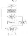
- the first embodiment is an embodiment in which the transmission of broadcast data and multicast data is not performed when a judgment standard is not fulfilled.
- Fig. 6 shows the process flow of the first embodiment, wherein the judgment standard is the judgment standard (i) in the earlier overview of the first invention.
- the processing may be performed by the base station 14 or may be performed by the wireless network control device 13.
- step 1 When multicast (broadcast) services have begun and the service area of the base station is divided into one or more sectors (zones), processing to confirm the existence of terminals receiving services is performed in each of these zones (step 1). Details on the terminal existence confirmation processing will be provided subsequently with reference to Fig. 9.
- step 2 It is then judged from the results of step 1 whether the number of terminals in each zone is "0" (step 2). If the number of terminals is "0", transmission stoppage processing for the wireless channel in the relevant zone is performed (step 3). Further, when the base station 14 performs transmission stoppage processing, transmission on a physical channel is stopped. Further, in cases where the wireless network control device 13 performs the transmission stoppage processing, transmission on a logical channel is stopped.
- processing to start (continue) transmission of broadcast data and multicast data on a wireless channel is performed. Further, the transmission of broadcast data and multicast data is started on a physical channel when the base station performs processing to start transmission and on a logical channel when the wireless network control device performs processing to start (continue) transmission.
- steps 1, 2, 5, and 6 may be performed by the wireless network control device 13, while steps 3 and 4 may be executed by the base station 14.
- the wireless network control device 13 performs the judgment of step 2 and then communicates the judgment results to the base station 14, whereupon the base station 14 terminates the physical channel.
- Fig. 7 shows a process flow that illustrates the operation of the terminal.
- the terminal 15 performs the following operation each time there is a call request from the base station 14 (or the wireless network control device 13). That is, terminal 15 performs reception processing in response to a call request from the base station 14 (or the wireless network control device 13) (step 1), and transmits a call response to the base station (wireless network control device) in response to a call request (step 2).
- the judgment standard is "the existence of terminals receiving a supply of services " in the first embodiment, the judgment standard may be the judgment standard (ii) in the earlier overview of the first invention.
- the judgment standard (ii) is "service quality, number of services, and number of terminals using the services (or the estimated number of terminals using services)". The lowest service quality required by each of the services is calculated and the transmission amount required to supply all the services is determined and, in cases where the transmission amount exceeds the transmission amount allocated to the multicast (broadcast), services with a small number of terminals using the services are terminated to establish a transmission amount that is equal to or below the allocated transmission amount.
- Fig. 8 shows the process flow of the first modified example and is an example of a case where processing to confirm the number of terminals and the transmission amount required to transmit all the services is performed by the base station 14 or the wireless network control device 13.
- processing to confirm the number of terminals receiving services is performed in the zone of each sector of the base station 14 (step 1). Processing to confirm the number of terminals will be described below with reference to Fig. 10.
- step 2 It is judged whether the total transmission amount of services exceeds the total transmission amount allocated to multicast (broadcast) in a zone (step 2).
- the number of terminals for which services can be continued is judged (step 3).
- wireless-channel transmission stoppage processing is performed (step 4). Further, in cases where the base station 14 performs the transmission stoppage processing, transmission on a physical channel is terminated. Further, when the wireless network control device 13 performs the transmission stoppage processing, transmission on a logical channel is terminated.
- step 5 processing to start (continue) transmission on a wireless channel is performed (step 5).
- the transmission of broadcast data and multicast data is started on a physical channel when the base station performs processing to start transmission and on a logical channel when the wireless network control device performs processing to start (continue) transmission.
- step 6 it is judged whether multicast (broadcast) services have ended (step 6) and, when services have ended, the operation is terminated.
- steps 1, 2, 3 and 6 may be performed by the wireless network control device 13, while steps 4 and 5 may be executed by the base station 14.
- the wireless network control device 13 performs the judgment of step 2 or three and then communicates the judgment result to the base station 14, whereupon the base station 14 terminates the physical channel.
- Fig. 9 shows the process flow of terminal existence confirmation.
- the base station 14 or wireless network control device 13 sets a variable x, which indicates the reference number of the terminal in a zone existence list at 1 (step 1). Thereafter, it is judged whether there is a request to stop the supply of services from the terminal (reduction request) with respect to the zone supplying services (step 2).
- step 2 When there is a reduction request in step 2, a terminal with a reduction request is erased from the list (step 3) and the processing moves on to the processing of step 4. Thereafter, it is judged whether there has been a service supply request (registration request) from a terminal with respect to a zone supplying services (step 4). In the following three cases, it is judged that there has been a service supply request:
- step 4 When there is a registration request in step 4, a terminal for which there is a request is registered in the list and the processing moves to step 6.
- variable y which indicates the number of call repetitions in the existence processing, is set at 1 (step 6), a call from a user whose terminal reference number is x is made (step 7), response reception processing for the user with the reference number x in response to this call is performed (step 8), and it is judged whether there has been a response from the user with the reference number x (step 9).
- the terminal existence confirmation processing is stopped when a terminal exists.
- step 9 it is judged whether the call repetition number y has reached the repetition termination number (step 11). As long as the repetition termination number has not been reached, the call repetition variable y is incremented (step 12) and the processing of step 7 and subsequent steps is repeated.
- step 11 If the repetition termination number is reached in step 11, non-respondent users are erased from the list (step 13). Subsequently, the terminal reference number is incremented (step 14) and it is judged whether confirmation of the existence of all terminals has been performed (step 15). If confirmation of the existence of all terminals is not complete, the processing of step 2 and subsequent steps is repeated and, when no terminals exist when confirmation of the existence of all terminals is complete, the terminal existence confirmation processing is terminated.
- Fig. 10 shows the process flow for confirming the number of terminals.
- the processing of steps 1 to 8 is the same as the processing of steps 1 to 8 in Fig. 9.
- step 9 it is judged whether the call repetition number y has reached the repetition termination number (step 12). As long as the call termination number has not been reached, the call repetition variable y is incremented (step 13) and the processing of step 7 and subsequent steps is repeated. If the call repetition number y has reached the repetition termination number in step 12, users from which there has been no response are erased from the list (step 14).
- the second embodiment is an example in which the optimum wireless channel for transmitting broadcast data and multicast data is selected in accordance with a judgment standard.
- Fig. 11 shows the process flow of the wireless network control device 13 and represents a case where the judgment standard is the judgment standard (i) of the earlier overview of the second invention (the number of terminals receiving a supply of services) and where the wireless channel selection condition is a.
- the wireless network control device 13 judges whether services are supplied on a common physical channel in the zone of each sector of the base station 14 supplying the services (step 1). If the physical channel supplying the services is a common physical channel, processing to confirm the number of terminals receiving services is performed (step 2). Subsequently, it is judged whether the number of terminals in the zone of each sector is "0" (step 3) and, if the number of terminals is not zero, it is judged whether the number of terminals in the zone is equal to or less than x1 (step 4).
- step 5 If the number of terminals is not equal to or less than x1, because there is an adequate number of terminals for supplying services on a common physical channel, the transmission on the common physical channel is continued (step 5). However, if the number of terminals is equal to or less than x1, there are an insufficient number of terminals for supplying services on a common physical channel and, therefore, a change is made to dedicated physical channels (step 6).
- step 7 transmission stoppage processing is performed (step 7).
- step 8 it is judged whether the physical channel for supplying the services is-an dedicated physical channel (step 8). If the physical channel for supplying the services is in dedicated physical channel, it is judged whether the number of terminals in the zone is equal to or more than x2 (step 9). In this case, the physical channel for supplying the services is an dedicated physical channel and the number of dedicated physical channels corresponds to the number of terminals, and, therefore, the number of terminals is found from the number of dedicated physical channels.
- step 10 If the number of terminals is equal to or more than x2, there is sufficient number of terminals for supplying services on a common physical channel and, therefore, a change is made to a common physical channel (step 10). However, if the number of terminals is not equal to or more than x2, there is inadequate number of terminals for supplying services on a common physical channel and, therefore, the supply of services on dedicated physical channels is continued (step 11).
- step 12 if the physical channel for supplying the services is not an dedicated physical channel in step 8, because all the terminals in the cell terminate services during the supply of services on dedicated physical channels, that is, because transmission stoppage is in progress, transmission stoppage is continued (step 12).
- steps 5 to 7 and 10 to 12 it is judged whether multicast (broadcast) services have ended (step 13) and, if services have not ended, the processing returns to step 1 and the processing of step 1 and subsequent steps is repeated. If services have ended, processing is terminated.
- Fig. 12 shows the process flow of a base station.
- step 1 When multicast (broadcast) services have begun, it is judged whether a change from a common physical channel to an dedicated physical channel has been instructed by the wireless network control device 13 (step 1).
- step 2 If an instruction for a change to an dedicated physical channel has been issued, processing for the change to an dedicated physical channel is performed (step 2). On the other hand, if an instruction for a change to an dedicated physical channel has not been made, it is judged whether a change from an dedicated physical channel to a common physical channel has been issued by the wireless network control device 13 (step 3).
- processing for the change to a common physical channel is performed (step 4). However, if a change to a common physical channel has not been instructed, it is considered that no instruction for a physical-channel change has been made by the wireless network control device 13.
- step 5 it is judged whether multicast (broadcast) services have ended. If services have not ended, processing returns to step 1, whereupon subsequent steps is repeated and, if services have ended, processing is terminated (step 6).
- Fig. 13 shows the process flow of the terminal.
- step 1 When multicast (broadcast) services have begun, it is judged whether a call request from the base station 14 (or the wireless network control device 13) has been made (step 1). If a call request has been made, processing to receive the call from the base station (wireless network control device) is performed (step 2) and, following reception processing, a response is transmitted to the base station (wireless network control device) (step 3).
- step 4 it is judged whether there is a physical-channel change request. If there is a physical-channel change request, processing to change the physical channel is performed (step 5).
- step 6 it is judged whether multicast (broadcast) services have ended (step 6) and, if these services have not ended, the processing returns to step 1, whereupon the processing of step 1 and subsequently steps is repeated and, if services have ended, the processing is terminated (step 7).
- the first modified example is a method for determining the wireless channel in a case of adopting the wireless channel selection condition b of the judgment standard (i) described in the overview of the second invention and Fig. 14 shows the process flow of the wireless network control device 13 of the first modified example.
- step 1 When multicast (broadcast) services have begun, processing to confirm the number of terminals receiving services is performed (step 1). After the processing to confirm the number of terminals receiving services has ended, it is judged whether the number of terminals in the zone of each sector is "0" (step 2). If the number of terminals is not "0", it is judged whether the logical channel for supplying the services is a common logical channel (step 3). If the logical channel for supplying the services is a common logical channel, it is judged whether the number of terminals in the zone is equal to or less than x1.
- the wireless resources can be efficiently used by supplying services on a common logical channel and, therefore, the transmission on the common logical channel is continued (step 5). However, if the number of terminals is equal to or less than x1, the wireless resources can be efficiently used by supplying services on an dedicated logical channel and, therefore, a change is made to dedicated logical channels (step 6).
- step 7 processing to stop transmission (continue stoppage) is performed (step 7). Further, if the logical channel for supplying the services is not a common logical channel in step 3, an dedicated logical channel is being used and, therefore, a judgment standard for an dedicated logical channel is used and it is judged whether the number of terminals in the zone is equal to or more than x2 (step 8).
- wireless resources can be used efficiently by supplying services on a common logical channel and, therefore, a change is made to a common logical channel (step 9).
- wireless resources can be efficiently used by supplying services on dedicated logical channels and, therefore, the supply of services on dedicated logical channels is continued (step 10).
- step 11 After the processing of steps 5 to 7 and 9 to 10, it is judged whether the multicast (broadcast) services have ended (step 11). If services have not ended, processing returns to step 1 and the processing of step 1 and subsequent steps is repeated. If services have ended, the processing is terminated.
- the second modified example is a method of determining the wireless channel in a case of adopting the judgment standard (ii) described in the overview of the second invention (the transmission power required to supply services) and Fig. 15 shows the process flow of the wireless network control device.
- step 1 processing to calculate the transmission power of all the terminals receiving services is performed.
- the processing to calculate transmission power will be described subsequently with reference to the process flow of Figs. 16 to 18.
- step 2 After the processing to calculate the transmission power has ended, it is judged whether the transmission power within the zone of each sector is 0 (step 2). If the transmission power is not 0, it is judged whether the physical channel supplying the services is a common physical channel (step 3).
- the physical channel for supplying the services is a common physical channel
- the transmission power difference within the zone that is, the common physical channel transmission power is Pc
- the dedicated physical channel transmission power is Pd
- step 7 processing to stop transmission (continue stoppage) is performed (step 7).
- step 11 it is judged whether the multicast (broadcast) services have ended. In cases where services have not ended, the processing returns to step 1 and the processing of step 1 and subsequent steps is continued. If services have ended, the processing is terminated (step 12).
- Fig. 16 shows the process flow for calculating transmission power and steps 1 to 8 are the same as those in Fig. 9.
- step 9 it is judged whether there has been a response from the terminal with the reference number x (step 9). If there has been a response from the terminal, the terminal is registered in the list and updated together with the reception power value of the reference signal of the terminal (pilot signal) (step 10). Further, the call response from the terminal includes the reported value for the reception power of the reference signal of the terminal.
- step 11 it is judged whether the call repetition number y has reached the repetition termination number. If the repetition termination number has not been reached, the call repetition variable y is incremented (step 12), and the processing returns to step 7, whereupon the processing of step 7 and subsequent steps is repeated. If the repetition termination number has been reached, users from which there has been no response are erased from the list (step 13).
- the reference number of the terminal is incremented (step 14) and it is judged whether confirmation of the existence of all terminals has been performed (step 15). If there are terminals for which the existence confirmation has not then performed, the processing returns to step 2, and the processing of step 2 and subsequent steps is repeated. If confirmation of the existence of all terminals has ended, the reception power values of the reference signals reported from the terminals are totaled to determine the transmission power when an dedicated physical channel is used (step 16). Further, the transmission power when a common physical channel is used is set beforehand.
- the third modified example is an example in which the transmission power is calculated by performing the terminal call for each group and Fig. 17 shows the process flow for calculating transmission power of the third modified example.
- the base station 14 or wireless network control device 13 performs processing to receive responses from the terminals with reference numbers x1 to x2 (step 8) and it is judged whether there has been a response from the terminals with reference numbers x1 to x2 (step 9).
- the terminal number is registered or updated in the list together with the reception power value of the reference signal of this terminal (pilot signal) (step 10). Further, the call response from the terminal includes the reception power report value of the reference signal of the terminal.
- step 11 it is judged whether there has been a response from all the terminals with reference numbers x1 to x2(step 11). If there has been a response from all the terminals x1 to x2, the processing of step 16 is performed and, if there has been no response, it is judged whether the call repetition number y has reached the repetition termination number (step 12). If the repetition termination number has not been reached, the call repetition variable y is incremented (step 13)and, among the terminals with reference numbers x1 to x2, the call data of terminals for which there has been no call response is multiplexed and transmitted to the terminals before a call is made (step 14), whereupon the processing of step 8 and subsequent steps is repeated.
- step 12 terminals from which there has been no response are erased from the list (step 15).
- grouping under reference numbers in a list was implemented above, grouping may also be implemented by means of a lower digit n for the telephone number or a lower digit n for the device number. Further, the terminal processing operation is the same as that shown in Fig. 13.
- Fig. 18 shows another process flow of the transmission power calculation processing of the third modified example. This process flow differs from the process flow in Fig. 17 in that, (1) step 14 in Fig. 17 has been removed; (2) step 21 is provided and the base station issues a reception response confirmation communication to the terminal making the call response; (3) the terminal receiving the reception response confirmation communication does not respond even when called.
- Fig. 19 shows the process flow of the terminal of the third modified example in Fig. 18.
- step 1 When multicast (broadcast) services have begun, it is judged whether there has been a call request from the base station (step 1). If there has been a call request, processing to receive a call from the base station is performed (step 2). Subsequently, it is judged whether the received data is a call regarding the non-communication of reception response confirmation (step 3).
- a call regarding the non-communication of reception response confirmation is a call to the effect that a reception response confirmation communication has not yet been received. In the event of a call regarding the non-communication of reception response confirmation, a call response is issued to the base station (step 4).
- step 1 if there is no call request from the base station, it is judged whether there has been a reception response communication from the base station (step 5). If there has been a reception response communication, processing to receive the reception response confirmation communication is performed (step 6). However, if there has been no reception response communication, it is judged whether there has been a physical-channel change request (step 7). If there has been a physical-channel change request, processing to change the physical channel is performed (step 8).
- step 9 it is judged whether multicast (broadcast) services have ended. If the services have not ended, the processing returns a step 1 and the processing of step 1 and subsequent steps is repeated. However, if the services have ended, the processing is terminated (step 10).
- the fourth modified example is a method of determining the wireless channel in a case of adopting the judgment standard (iii) described in the overview of the second invention (the interference amount generated when services are supplied) and Fig. 20 shows the process flow of the wireless network control device.
- the terminal receiving services calculates the interference amount with respect to other communications (step 1).
- the processing to calculate the interference amount is performed by the base station or the wireless network control device 13 as detailed subsequently and the calculation results are acquired.
- step 2 After the processing to calculate the interference amount has ended, it is judged whether the number of terminals in the zone of each sector is 0 (step 2). Further, processing to confirm the number of terminals during the interference amount calculation processing is performed.
- step 3 If the number of terminals is not 0, it is judged whether the physical channel providing the services is a common physical channel (step 3).
- step 2 if the number of terminals is 0, processing to stop transmission (continue stoppage) is performed (step 7). Further, in step 3, if the physical channel for supplying the services is not a common physical channel, an dedicated physical channel is employed and, therefore, a judgment standard for an dedicated physical channel is employed and it is judged whether the interference power difference (Ic-Id) is equal to or less than -x2 (step 8).
- Ic-Id interference power difference
- step 11 After the processing of steps 5 to 7 and 9 to 10, it is judged whether the multicast (broadcast) services have ended (step 11). In cases where services have not ended, the processing returns to step 1 and the processing of step 1 and subsequent steps is continued. If services have ended, the processing is terminated.
- the processing of the base station and terminal is the same as that shown in Figs. 12 and 13.
- Fig. 21 shows the process flow of an interference amount calculation by the base station on the wireless network control device 13 and is substantially the same as the process flow for calculating the transmission power shown in Fig. 16.
- the difference lies in the fact that, in step 16, the interference power when an dedicated physical channel is employed is determined by using reception power values reported by the terminal. Further, the interference power when a common physical channel is employed is calculated by using a preset transmission power value.
- Fig. 22 is an explanatory view of an interference power calculation.
- the items of terminals 15 4 to 15 6 which are not channel switching targets, are referenced from the list of interference power measurement values reported when all the terminals 15 1 to 15 6 communicate with the base station 14 and the interference power from the terminals 15 1 to 15 3 constituting the channel-type switching targets is calculated.
- the interference power recorded in the list is the total of (1) the interference from other cells, (2) interference from channels constituting channel-type switching targets, and (3) interference from the other channels within the cell in question.
- the interference power from other cells has a value that is dependent on the propagation loss and is determined beforehand (as the propagation loss increases, interference from the other cells increases). Further, the interference from channels constituting channel-type switching targets and the interference from the other channels within the cell in question are established by means of the ratio between the transmission powers P1 and P2 transmitted from the base station 14. Hereinabove, the interference power of channels constituting channel-type switching targets is calculated.
- the interference power recorded in the list It
- the interference power of the other cells Io
- the transmission power of channels constituting channel-type switching targets P1
- the transmission power from the other channels within the cell in question P2.
- P1 and P1' are the total of the reception power report values from reporting terminals in step 10 in Fig. 20 when the physical channel is an dedicated physical channel and are transmission power values determined beforehand by the sys tem when the physical channel is a common physical channel.
- the fifth modified example is a method of determining the wireless channel in a case of adopting the judgment standard (iv) described in the overview of the second invention (combination of services) and Fig. 23 shows the process flow of a wireless network control device.
- a list of service combinations for the common physical channel is retrieved (step 1). Subsequently, it is judged whether there is a suitable combination (step 2). For example, N broadcasting data items can be transmitted on a common physical channel and, where not all N broadcasting data items are transmitted, broadcasting data for new services can be transmitted on the common physical channel. Therefore, if there is scope in the common physical channel, it is judged that a suitable combination exists and, when there is no scope, it is judged that the combination is not a suitable combination.
- step 3 it is judged whether the physical channel supplying the services is a common physical channel (step 3). If the physical channel supplying the services is a common physical channel, the transmission on a common physical channel is continued (step 4). If the physical channel supplying the services is not a common physical channel, a change is made to a common physical channel (step 5).
- step 6 it is judged whether the number of terminals receiving new services is large or small (step 6). If the number of terminals receiving new services is large, transmission is performed on a new common physical channel (step 7). However, if the number of terminals receiving new services is small, transmission is performed on dedicated physical channels (step 8).
- step 9 it is judged whether multicast (broadcast) services have ended. If the services have not ended, the processing returns to step 1 and the processing of step 1 and subsequent steps is repeated. If the services have ended, the processing is terminated. Further, the processing of the base station and terminal is the same as that in Figs. 12 and 13.
- the third embodiment is an embodiment of a communication method in which, when a terminal receiving a supply of services has moved to a region that can be presumed to allow the terminal to receive services from another zone, the terminal issues a request to a network device to transmit broadcasting data (broadcast data or multicast data) from the other zone and the network device commences transmission on the basis of the request.
- broadcasting data broadcast data or multicast data
- Fig. 24 is an explanatory view of the zone-switching procedure of the third embodiment.
- Terminal 15 issues a request to start transmission by means of a zone update communication to the wireless network control device 13 via base station 14 2 of the movement-destination zone (1).
- the wireless network control device 13 issues a transmission start communication to the base station 14 2 in the movement-destination zone as shown in table 1 in accordance with the state of the movement-destination zone (only in a case where the transmission has stopped).
- the wireless network control device 13 also issues a response to a request for an update communication confirmation to terminal 15 via the movement-destination base station 14 2 ...(2).
- the base station 14 2 of the movement-destination zone starts to transmit broadcast data or multicast data in accordance with the communication from the wireless network control device 13 ... (3).
- Terminal 15 starts to receive the broadcast data or multicast data in the movement-destination zone at the time designated by the wireless network control device 13 ...(4). State of movement destination Response to terminal Communication to movement-destination zone Transmission stoppage Update communication confirmation Start of transmission Common physical channel Update communication confirmation None
- a request to start transmission by means of a zone update communication from terminal 15 is made to the wireless network control device 13 via the movement-destination base station 14 2
- a request to start transmission by means of a zone update communication can also be made to the wireless network control device 13 via the base station 14 1 of the movement-source zone as shown in Fig 25.
- Fig. 26 shows the process flow of the wireless network control device 13.
- the wireless network control device 13 judges whether there is a request for a zone update communication from the terminal 15 when multicast (broadcast) services have begun (step 1). If there is a request for a zone update communication, it is judged whether the movement-destination base station 14 2 has stopped transmission (step 2). If the movement-destination base station 14 2 has stopped transmission, the transmission start communication is transmitted to the movement-destination base station (step 3).
- step 4 Following the process of step 3 or if the movement-destination base station 14 2 has not stopped transmission in step 2 (is communicating on a common physical channel), an update communication confirmation is transmitted to terminal 15 (step 4). A short while afterward or when there is no zone update communication in step 1, it is judged whether multicast (broadcast) services have ended (step 5). If services have not ended, the processing returns to step 1 and the processing of step 1 and subsequent steps is repeated. If services have ended, the processing is terminated.
- multicast broadcast
- Fig. 27 shows the process flow of the movement-destination base station.
- step 1 When multicast (broadcast) services have begun; it is judged whether transmission has stopped (step 1). If transmission has stopped, it is judged whether there is a transmission start communication from the wireless network control device 13 (step 2). If there is a transmission start communication, transmission start processing is performed (step 3).
- step 4 After the processing of step 3 has ended or in a case where transmission has not stopped in step 1 or there is no transmission start communication in step 2, it is judged whether multicast (broadcast) services have ended (step 4). If services have not ended, the processing returns to step 1 and the processing of step 1 and subsequent steps is repeated. If the services have ended, the processing is terminated.
- Fig. 28 shows the process flow of the terminal.
- step 1 When multicast (broadcast) services have begun, it is judged whether a zone update condition (described later) is fulfilled (step 1). If the zone update communication condition is fulfilled, processing to transmit a zone update communication is performed (step 2). A short while afterward, processing to receive the update communication confirmation is performed (step 3) and processing to receive multicast (broadcast) data is executed (step 4).
- a zone update condition described later
- step 5 After the processing of step 4 is complete or if the zone update communication condition is not fulfilled in step 1, it is judged were the multicast (broadcast) services have ended (step 5). If the services have not ended, the processing returns to step 1 and the processing of step 1 and subsequent steps is repeated. If the services have ended, the processing is terminated.
- the zone update communication condition is that the following two first and second conditions be fulfilled.
- the second condition is that at least one peripheral zone satisfying the following equation Qs ⁇ Qn, x(where x is one value from 1 to n) should exist continuously for a fixed time.
- the third embodiment represents a case where the wireless network control device 13 has already transmitted multicast (broadcast) data on a logical channel to each base station and the movement-destination base station 14 2 transmits the above data to the terminal in accordance with an instruction from the wireless network control device 13.
- the wireless network control device 13 has not yet transmitted multicast (broadcast) data to the movement-destination base station 14 2 and the data is transmitted to the movement-destination base station 14 2 on a logical channel in accordance with a request from the terminal and is transmitted from the base station to the terminal.
- Fig. 29 is an explanatory view of a sequence of a modified example.
- Terminal 15 issues a request to the wireless network control device 13 to start transmission by means of a zone update communication via the movement-destination base station 14 2 .
- the wireless network control device 13 receives a zone update communication, same performs processing to start transmission as shown in table 2 in accordance with the state of the movement-destination base station 14 2 . That is, if the movement-destination base station 14 2 has stopped transmission, the wireless network control device 13 issues an instruction to transmit multicast (broadcast) data to the movement-destination base station 14 2 on a logical channel and to transmit the data to the terminal. Further, the wireless network control device 13 does nothing if the movement-destination base station 14 2 is transmitting the data on a common physical channel. State of movement destination Response to terminal Communication to movement-destination zone Transmission stoppage Update communication confirmation Start of transmission Common physical channel Update communication confirmation None
- the wireless network control device 13 issues a response to the request by sending an update communication confirmation to terminal 15 via the movement-destination base station 14 2 . Thereafter, terminal 15 starts receiving broadcast data or multicast data in the movement-destination zone at the time designated by the wireless network control device 13.
- terminal 15 issues a transmission start request to the wireless network control device 13 by means of a zone update communication via the movement-destination base station 14 2 .
- a request to start transmission can also be made to the wireless network control device 13 by means of the zone update communication via the base station 14 1 of the movement-source zone.
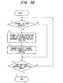
- Fig. 31 shows the process flow of the wireless network control device of a modified example. Further, the terminal processing is the same as that of the case of the third embodiment.
- the wireless network control device 13 judges whether there is a request for a zone update communication from terminal 15 when multicast (broadcast) services have begun (step 1). If there is a request for a zone update communication, the wireless network control device 13 judges whether the movement-destination base station 14 2 has stopped transmission (step 2). If the movement-destination base station 14 2 has stopped transmission, the transmission of multicast (broadcast) data is started on the logical channel to the movement-destination base station (step 3). As a result, the movement-destination base station 14 2 maps the common logical channel to the physical channel and transmits the data on the common physical channel.
- step 4 Following the processing of step 3 or if the movement-destination base station 14 2 has not stopped transmission in step 2, an update communication confirmation message is transmitted to terminal 15 (step 4).
- step 5 A short while afterward or when there is no zone update communication in step 1, it is judged whether multicast (broadcast) services have ended (step 5). If services have not ended, the processing returns to step 1 and the processing of step 1 and subsequent steps is repeated. If services have ended, the processing is terminated.
- 'zone update communication' and 'update communication confirmation' were performed via the same base station that may also be performed via different base stations.
- a communication to the movement destination is not issued when the movement-destination base station communicates on a common wireless channel but a communication may be issued regardless of the state of the movement-destination base station.
- a common physical channel and a common logical channel were used as the channel employed in the above embodiment. However, other channels, such as dedicated physical channels, dedicated logical channels, and a common physical channel could also be employed. These modified examples are also valid for the following embodiments.
- Fig. 32 is a modified example of Figs. 25 and 30 of the third embodiment and is an embodiment in which (1) physical-channel transmission and logical-channeltransmission are both performed and in which (2) processing with respect to the movement-source zone and processing to set the user-data transmission channel are added.
- the sequence of Fig. 32 is implemented in cases where, for example, the movement-source zone 14 1 communicates on a common physical channel and a common logical channel and the movement-destination zone 14 2 does not supply services.
- this sequence can also be applied to a case where the movement-source zone 14 1 communicates on a common physical channel and a common logical channel and the movement-destination zone 14 2 also communicates on a common physical channel and a common logical channel, and to a case where the movement-destination zone communicates on a common physical channel and a common logical channel, and so forth, for example.
- terminal 15 receives setting information on the wireless channel (physical channel, logical channel) following the zone shift from the wireless network control device 13 in the form of a communication regarding zone update reservation completion via the movement-source zone 14 1 . ...(3)
- the terminal 15 sets the wireless channel on the basis of the wireless channel information that is communicated by means of the zone update reservation completion communication. ... (4), (5).
- the setting of the user-data transmission channel is completed as a result of terminal 15 setting the wireless channel, whereupon the terminal starts reception. ...(6), (7).
- terminal 15 communicates the fact that 'the logical-channel or physical-channel transmission by the v zone base station can be stopped' to the network control device 13 by means of a zone-update completion communication. ...(8), (9)
- the wireless network control device 13 which has received the communication regarding zone update completion, checks the states of the movement-source zone 14 1 and, for example, checks whether another terminal that has set the same user transmission channel as the terminal 15 performing the zone shift exists in the movement-source zone. If such a terminal does not exist, the wireless network control device issues an instruction to the movement-source base station 14 1 to stop logical-channel transmissions and physical-channel transmissions and to cancel the wireless channel....(10)
- the movement-source base station 14 1 cancels the user-data transmission channel used by the terminal 15.
- the wireless network control device 13 transmits a zone-update-completion confirmation communication, which indicates that processing for a communication regarding zone update completion of (9) is finished, to terminal 15 and terminates the serial processing. ...(12)
- the terminal 15 transmits a zone update reservation and, following receipt of a zone update reservation completion, in cases where terminal 15 has not moved to the reserved zone, in the following cases (i) to (iv), for example, the wireless network control device 13 cancels the reservation of multicast (broadcast) services and stops the transmission of multicast (broadcast) services of the reserved zone.
- a zone update reservation communication can also be transmitted to a plurality of movement destinations.
- a plurality of movement-destination information items is included in one message or the zone update reservation notification is transmitted dedicatedly to each of the movement destinations.
- 'zone update reservation' of (1) in Fig. 32 is communicated in cases where a plurality of zone update communications is issued, when a shift has not been made to this zone, the transmission of data of the zone to which the terminal has not moved is suspended.
- a zone update reservation is transmitted once again via the movement-destination zone 14 2 .
- the wireless network control device 13 is also able to send the zone update reservation completion of (3) to both the movement-source zone 14 1 and also the movement-destination zone 14 2 .
- the terminal receives the zone update reservation completion in the movement-source zone 14 1 prior to a zone update and in the movement-destination zone 14 2 following a zone update.
- Fig. 33 shows the process flowof the wireless network control device 13 in the sequence of Fig. 32.
- This process flow represents an embodiment in which, following the transmission of the 'zone update reservation completion', detection of the non-arrival of the terminal in the reserved zone is performed by means of a time base. When detection is unnecessary, steps 2, 6, 10, and 11 are not required and 'processing to receive a zone-update completion communication' is performed in place of step 6.
- Fig. 35 shows the process flow of terminal 15. Detection of the zone shift state can also be rendered unnecessary if the state has the same conditions as the zone update reservation conditions.
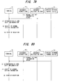
- Fig. 36 is a sequence for a case where a message is transmitted by extending a plurality of wireless network control devices 13a and 13b in the embodiment of Fig. 32.
- Fig. 37 shows the process flow for the movement-source wireless network control device 13a in the sequence of Fig. 36 and Fig. 38 shows the process flow of the movement-destination wireless network control device 13b.
- Fig. 39 is an example of a sequence in a case where a plurality of wireless network control devices 13a and 13b is mounted in the embodiment of Fig. 32.
- Fig. 40 shows the process flow of the movement-source wireless network control device 13a of Fig. 39.
- Fig. 41 shows the process flow of the movement-destination wireless network control device 13b.
- the fourth embodiment is an embodiment in which a network device detects the fact that a terminal exists in a region that can be presumed to allow the terminal to receive services from another zone and in which the transmission of broadcast data or multicast data on a wireless channel from the other zone is started.
- Fig. 42 is an explanatory view of the zone-switching sequence of the fourth embodiment.
- Terminal 15 communicates a measurement value report (reception field strength and so forth) to the wireless network control device 13 via the movement-destination base station 14 2 ...(1).
- the wireless network control device 13 Upon receiving the measurement value report, the wireless network control device 13 detects the fact that the terminal has moved to another zone or is moving to another zone on the basis of the measured value from the terminal and determines zone-shift implementation ... (2). Subsequently, the wireless network control device 13 issues a communication to commence transmission to the movement-destination base station as shown in table 3 in accordance with the state of the movement-destination base station 14 2 . That is, if the movement-destination base station 14 2 has stopped transmission, the wireless network control device 13 issues an instruction to start transmission and does nothing if the movement-destination base station 14 2 is transmitting the data on a common physical channel.... (3) State of movement-destination base station Response to terminal Communication to movement-destination zone (movement-destination base station ) Transmission stoppage Channel setting communication Start of transmission Common physical channel Channel setting communication None
- the wireless network control device 13 issues a channel setting communication to terminal 15 via the movement-destination base station 14 2 ...(4).
- the movement-destination base station 14 2 commences transmission in accordance with the transmission start communication from the wireless network control device 13 ...(5).
- terminal 15 starts to receive broadcast data or multicast data in the movement-destination zone at the time designated by the wireless network control device 13 ...(6).
- a transmission start completion and channel setting completion are sent back to the wireless network control device 13 in response to the transmission start communication and channel setting communication respectively....(3)',(4)'
- a measurement value report is sent from terminal 15 to the wireless network control device 13 via the movement-destination base station 14 2 in Fig. 42
- the measurement value report can also be sent to the wireless network control device 13 via the base station 14 1 of the movement-source zone as shown in Fig. 43.
- Fig. 44 shows the process flow of the wireless network control device of the fourth embodiment.
- the wireless network control device 13 judges whether there is a measurement value report from terminal 15 when multicast (broadcast) services have begun (step 1). If there is a measurement value report, the wireless network control device 13 decides, based on the report value, whether the terminal has shifted zone and judges how the zone shift is implemented on the basis of this decision (step 2).
- step 3 it is judged whether the movement-destination base station 14 2 has stopped transmission. If the movement-destination base station has stopped transmission, a transmission start communication is transmitted to the movement-destination base station (step 4).
- step 5 Following the processing of step 4 or if the movement-destination base station has not stopped transmission in step 3 (transmission is taking place on a common physical channel), a channel setting communication is transmitted to terminal 15 (step 5).
- step 6 it is judged whether multicast (broadcast) services have ended (step 6). If services have not ended, the processing returns to step 1 and the processing of step 1 and subsequent steps is repeated. If services have ended, the processing is terminated. Further, the operation of the movement-destination base station is the same as that of the third embodiment.
- Fig. 45 shows the process flow of the terminal.
- step 1 When multicast (broadcast) services have begun, it is judged whether a measurement value report condition (described later) is fulfilled (step 1). If the measurement value report condition is fulfilled, processing to transmit a measurement value report is performed (step 2).
- step 2 receipt of a channel setting communication is awaited for a fixed time and it is judged whether the channel setting communication has been received (step 3). If a channel setting communication has been received, channel setting communication processing is performed (step 4). Subsequently, processing to receive multicast (broadcast) data in the movement-destination zone is performed (step 5).
- step 6 it is judged whether the multicast (broadcast) services have ended. If the services have not ended, the processing returns to step 1 and the processing of step 1 is and subsequent steps is repeated. If the services have ended, the processing is terminated (step 7).
- the operation of the movement-destination base station is the same as that of the third embodiment.
- Fig. 46 is an explanatory view of a measurement value report condition.
- the measurement report condition is fulfilled when the reception quality of a reference signal A in the movement-source zone deteriorates, the reception quality of a reference signal B in the movement-destination zone improves, and the reception quality in the movement-destination zone continues to be more favorable for a fixed time t or more than the reception quality in the movement-source zone.
- a measurement value report is issued to the wireless channel control device 13 via the base station 14 1 of the movement-source zone as shown in Fig. 43
- the reference-signal reception quality is raised by ⁇ x and a measurement value report can also be issued from the periphery of the region that allows multicast (broadcast) services to actually be received.
- the time required for zone switching can be extended, for example.
- the fourth embodiment represents a case where multicast (broadcast) data has already been transmitted on a logical channel to each of the base stations by the wireless network control device 13 and the movement-destination base station 14 2 transmits this data to a terminal in accordance with an instruction from the wireless network control device 13.
- the modified example represents a case where the multicast (broadcast) data has not been transmitted to the movement-destination base station 14 2 by the wireless network control device 13 and in which the data is transmitted to the movement-destination base station 14 2 on a logical channel on the basis of the measurement value report from the terminal and is then transmitted to the terminal from the base station.
- Fig. 47 is an explanatory view of a sequence of a modified example.
- Terminal 15 issues a measurement value report to the wireless network control device 13 via the movement-destination base station 14 2 ...(1).
- the wireless network control device 13 Upon receiving the measurement value report, the wireless network control device 13 detects the fact that the terminal has moved to another zone or is moving to another zone on the basis of the measurement value from terminal 15 and determines the zone shift implementation ...(2).
- the wireless network control device 13 performs processing to commence transmission as shown in table 4 in accordance with the state of the movement destination...(3). That is, if the movement-destination base station 14 2 has stopped transmission, the wireless network control device 13 issues an instruction to the base station to transmit multicast (broadcast) data to the movement-destination base station 14 2 on a logical channel and to transmit the data to the terminal. Further, the wireless network control device 13 does nothing if the movement-destination base station 14 2 is transmitting the data on the common physical channel.
- the wireless network control device 13 issues a channel setting communication to terminal 15 via the movement-destination base station 14 2 ...(4).
- terminal 15 starts reception in the movement-destination zone at the time designated by the wireless network control device 13.
- the measurement value report is transmitted from terminal 15 to the wireless network control device 13 via the movement-destination base station 14 2 in Fig. 47, the measurement value report can also be issued to the wireless network control device 13 via the base station 14 1 in the movement-source zone as shown in Fig. 48.
- Fig. 49 shows the process flow of the wireless network control device of a modified example.
- This process flow is substantially the same as the process flow of the embodiment in Fig. 44 but the difference lies in the processing of step 4.
- step 4 of the embodiment if the movement-destination base station 14 2 has stopped transmission, the wireless network control device transmits a transmission start communication to the movement-destination base station. However, in the case of the modified example, transmission to the movement-destination base station is started. That is, if the movement-destination base station 14 2 has stopped transmission, the wireless network control device issues an instruction to the base station to transmit multicast (broadcast) data to the movement-destination base station 14 2 on a logical channel and to transmit the data to the terminal.
- multicast multicast
- the fifth embodiment is an embodiment in which, when a terminal receiving a supply of services is in a region that can be presumed to allow the terminal to receive services from another zone, the terminal issues a request to a network device for a wireless channel for supplying the services from the other zone and the network device communicates by allocating a wireless channel.
- Fig. 50 is an explanatory view of the zone-switching procedure of the fifth embodiment.
- Terminal 15 issues a request for wireless resources to the wireless network control device 13 by means of a channel setting request via the movement-destination base station 14 2 ...(1).
- the wireless network control device 13 Upon receiving the channel setting request, the wireless network control device 13 issues a channel setting communication to the movement-destination base station 14 2 as shown in table 5 in accordance with the state of the movement-destination base station...(2). Further, a response is made to the request by transmitting a channel setting communication to the terminal via the movement-destination base station...(2).
- the movement-destination base station 14 2 starts to transmit to the terminal on the channel that corresponds with the communication from the wireless network control device 13 (an dedicated physical channel or common physical channel)...(3).
- Terminal 15 starts to receive multicast data or broadcast data in the movement-destination zone at the time designated by the wireless network control device 13 ...(4).
- State of terminal State of movement destination Terminal operation Response to terminal Communication to movement-destination zone Dedicated physical channel Stopped Request to wireless network control device for wireless resources Channel setting communication Channel setting communication Dedicated physical channel Dedicated physical channel Request to wireless network control device for wireless resources Channel setting communication Channel setting communication Dedicated physical channel Common physical channel Request to wireless network control device for wireless resources Channel setting communication Channel setting communication Common physical channel Stopped Request to wireless network control device for wireless resources Channel setting communication Channel setting communication Common physical channel Dedicated physical channel Request to wireless network control device for wireless resources Channel setting communication Channel setting communication Common physical channel Common physical channel Request to wireless network control device for wireless resources Channel setting communication Channel setting communication Common physical channel Common physical channel Request to wireless network control device for wireless resources Channel setting communication Channel setting communication Channel setting communication Channel setting communication Channel setting communication
- a channel setting request is sent from terminal 15 to the wireless network control device 13 via the movement-destination base station 14 2 in Fig. 50
- the channel setting request can also be sent to the wireless network control device 13 via the base station 14 1 in the movement-source zone as shown in Fig. 51.
- Fig. 52 shows the process flow of the wireless network control device of the fifth embodiment.
- the wireless network control device 13 judges whether there is a channel setting request from terminal 15 when multicast (broadcast) services have begun (step 1). If there is a channel setting request, the wireless network control device 13 transmits a channel setting communication to the movement-destination base station 14 2 (step 2). As a result, the movement-destination base station 14 2 transmits multicast data or broadcast data to the terminal on the channel thus set (dedicated physical channel or common physical channel).
- the wireless network control device 13 transmits a channel setting communication to the terminal 15 (step 3).
- step 4 the processing returns to step 1 and the processing of step 1 and subsequent steps is repeated. If services have ended, the processing is terminated (step 5).
- Fig. 53 shows the process flow of the movement-destination base station.
- the movement-destination base station 14 2 judges whether there has been a channel setting communication from the wireless network control device 13 when multicast (broadcast) services have begun (step 1). If there is a channel setting communication, the movement-destination base station 14 2 performs channel setting processing and commences transmission (step 2). That is, the movement-destination base station 14 2 transmits multicast data or broadcast data to the terminal on the channel thus set (dedicated physical channel or common physical channel).
- step 3 Following the end of the processing of step 2 or when there is no channel setting communication in step 1, it is judged whether multicast (broadcast) services have ended (step 3). If services have not ended, the processing returns to step 1 and the processing of step 1 and subsequent steps is repeated. If services have ended, the processing is terminated (step 4).
- the movement-destination base station 14 2 relays a channel setting communication to the terminal together with the channel setting request from terminal 15.
- Fig. 54 shows the process flow of the terminal.
- Terminal 15 judges whether the channel setting request condition is fulfilled when multicast (broadcast) services have begun (step 1). If the channel setting request condition is fulfilled, terminal 15 performs processing to transmit a channel setting request (step 2). Subsequently, terminal 15 performs processing to receive a channel setting communication (step 3). After receiving the channel setting communication, terminal 15 performs processing to receive multicast (broadcast) data on the channel thus set (dedicated physical channel or common physical channel) (step 4).
- step 5 the processing returns to step 1 and the processing of step 1 and subsequent steps is repeated. If services have ended, the process is terminated (step 6).
- the channel setting request condition in step 1 is the same as the 'zone update communication condition' of the third embodiment.
- Figs. 55 and 56 represent embodiments in which, in the sequences of Figs. 50 and 51 respectively, terminal 15 switches a physical channel receiving a supply of multicast (broadcast) services between physical channels of a plurality of types when a plurality of physical channels is set at the same time.
- the difference lies in the fact that, in Figs. 55 and 56, 'start of transmission' of procedure (3) in the sequences of Figs. 50 and 51 has been changed to 'change in mapping of data to physical channel'. That is, in Figs. 55 and 56, the movement-destination zone 14 2 transmits multicast (broadcast) data to terminal 15 by mapping the data to different channel types in accordance with a channel setting communication.
- the fifth embodiment represents a case where multicast (broadcast) data has already been transmitted on a logical channel to each of the base stations by the wireless network control device 13 and in which the movement-destination base station 14 2 transmits the data to the terminal in accordance with an instruction from a wireless network control device 13.
- multicast (broadcast) data is not transmitted to the movement-destination base station 14 2 by the wireless network control device 13 and the data is transmitted to the movement-destination base station 14 2 on a logical channel on the basis of the channel setting request from the terminal before being transmitted from the base station to the terminal.
- Fig. 57 is an explanatory view of the zone-switching procedure of a modified example.
- Terminal 15 issues a request for wireless resources to the wireless network control device 13 by means of a channel setting request via the movement-destination base station 14 2 ...(1).
- the wireless network control device 13 Upon receiving the channel setting request, the wireless network control device 13 sets the channel of the movement-destination base station 14 2 as shown in table 6 in accordance with the state of the movement-destination base station and performs transmission...(2). That is, if the movement-destination base station 14 2 has stopped transmission, an instruction is sent to the base station to transmit multicast (broadcast) data to the movement-destination base station 14 2 on a logical channel and to transmit the data to the terminal. The movement-destination base station 14 2 then starts to transmit to the terminal on the channel corresponding with the communication from the wireless network control device 13 (dedicated physical channel or common physical channel).
- the wireless network control device 13 sends the channel setting communication to terminal 15 as per table 6 in accordance with the state of the movement-destination base station...(3).
- Terminal 15 starts to receive broadcast data or multicast data in the movement-destination zone at the time designated by the wireless network control device 13...(4).
- State of terminal State of movement destination Terminal operation Response to terminal Settings for movement-destination zone Dedicated logical channel Stopped Request to wireless network control device for wireless resources Channel setting communication Channel setting, transmission Dedicated logical channel Dedicated logical channel Request to wireless network control device for wireless resources Channel setting communication Channel setting, transmission Dedicated logical channel Common logical channel Request to wireless network control device for wireless resources Channel setting communication None Common logical channel Stopped Request to wireless network control device for wireless resources Channel setting communication Channel setting, transmission Common logical channel Dedicated logical channel Request to wireless network control device for wireless resources Channel setting communication Channel setting, transmission Common physical channel Common physical channel Request to wireless network control device for wireless resources Channel setting communication None
- a channel setting request is sent from terminal 15 to the wireless network control device 13 via the movement-destination base station 14 2
- the channel setting request can also be sent to the wireless network control device 13 via the base station 14 1 of the movement-source zone as shown in Fig 58.
- Fig. 59 shows the process flow of the wireless network control device of a modified example.
- the wireless network control device 13 judges whether there is a channel setting request from the terminal when multicast (broadcast) services have begun (step 1). If there is a channel setting request, the wireless network control device 13 performs channel setting processing for the movement-destination base station 14 2 and commences transmission. That is, if the movement-destination base station 14 2 has stopped transmission, the wireless network control device 13 issues an instruction to the base station to transmit multicast (broadcast) data to the movement-destination base station 14 2 on a logical channel and to transmit the data to the terminal. The movement-destination base station 14 2 then starts to transmit to the terminal on the channel set by the wireless network control device 13 (dedicated logical channel or common logical channel).
- the wireless network control device 13 also transmits a channel setting communication to terminal 15 (step 3).
- step 4 it is judged whether multicast (broadcast) services have ended. If services have not ended, the processing returns to step 1 and the processing of step 1 and subsequent steps is repeated. If services have ended, the processing is terminated (step 5).
- Fig. 60 is a modified example of Figs. 51 and 58 of the fifth embodiment and represents an embodiment in which (1) physical-channel transmission and logical-channel transmission are both performed and in which (2) processing for the movement-source zone and processing to set the user-data transmission channel have been added.
- the sequence of Fig. 60 can also be applied to a case where, for example, the movement-source zone 14 1 communicates on a common physical channel and a common logical channel and the movement-destination zone 14 2 does not supply services or to a case where terminal 15 communicates on an dedicated physical channel and an dedicated logical channel at the movement destination when services are supplied on an dedicated physical channel.
- Fig. 61 shows the process flowof the wireless network control device 13 in the sequence of Fig. 60, wherein the part of step 3 in Fig. 33 has become steps 3 and 3'.
- Fig. 33 shows the operation of the wireless network control device 13 in a case where two states in which the movement-destination base station 14 1 is transmitting and not transmitting are captured. Hence, the judgment of the state of the movement-destination base station is 'whether transmission has stopped'.
- processing to judge whether services are being supplied on a wireless channel that is different from the wireless channel being used for transmission by the movement-destination base station as shown in step 3' is required and added.
- the operation of the movement-source base station 14 1 in the sequence of Fig. 60 performs the following operations in addition to the operation of the movement-source base station 14 1 in Fig. 34:
- Fig. 62 shows the process flow of terminal 15 in the sequence of Fig. 60 and differs from the process flow of Fig. 35 as a result of the addition of processing to change the channel type in step 5.
- the sequence in a case where a plurality of wireless network channels 13a and 13b is mounted in the embodiment of Fig. 60 performs a sequence that is the same as that of the third embodiment and the second modified example of (e-2-2).
- procedure (2) of Fig. 60 is executed in procedure (5) in this sequence
- procedures (4) to (8) of Fig. 60 are executed in procedure (9) in this sequence
- procedure (10) of Fig. 60 is performed in procedure (12) in this sequence.
- a sequence of a case where a plurality of wireless network channels 13a and 13b is mounted in the embodiment in Fig. 60 performs a sequence that is the same as that of the third embodiment and the third modified example of (e-2-3).
- procedure (2) of Fig. 60 is executed in procedure (4) in this sequence
- procedures (4) to (8) of Fig. 60 are executed in procedure (9) in this sequence
- procedure (10) of Fig. 60 is performed in procedure (13) in this sequence.
- the sixth embodiment is an embodiment of a mobile communication system in which a network device detects measurement results from a terminal receiving a supply of services or detects, from a report value, that the terminal exists in a region that can be presumed to allow the terminal to receive services from another zone, and sets the wireless channel to communicate on the wireless channel.
- Fig. 63 is an explanatory view of the zone-switching procedure of the sixth embodiment.
- Terminal 15 sends a measurement value report to the wireless network control device 13 via the mobile destination base station 14 2 ...(1).
- the wireless network control device 13 detects the fact that the terminal has moved to another zone or is moving to another zone on the basis of the measurement value from the terminal and determines the implementation of zone shift control ...(2).
- the wireless network control device 13 sends a channel setting communication to the movement-destination base station as shown in table 7 in accordance with the state of the movement-destination base station 14 2 ...(3).
- the wireless network control device 13 sends a channel setting communication to terminal 15 via the movement-destination base station...(4).
- the movement-destination base station 14 2 starts to transmit broadcast data or multicast data to the terminal in accordance with the channel communication from the wireless network control device 13...(5).
- Terminal 15 starts to receive the data in the movement-destination zone at the time designated by the wireless network control device 13.
- State of terminal State of movement destination Terminal operation Response to terminal Communication to movement-destination zone Dedicated physical channel Stopped Measurement value report to wireless network control device Channel setting communication Channel setting communication Dedicated physical channel Dedicated physical channel Measurement value report to wireless network control device Channel setting communication Channel setting communication Dedicated physical channel Common physical channel Measurement value report to wireless network control device Channel setting communication Channel setting communication Common physical channel Stopped Measurement value report to wireless network control device Channel setting communication Channel setting communication Common physical channel Dedicated physical channel Measurement value report to wireless network control device Channel setting communication Channel setting communication Common physical channel Common physical channel Measurement value report to wireless network control device Channel setting communication Channel setting communication Common physical channel Common physical channel Measurement value report to wireless network control device Channel setting communication Channel setting communication Channel setting communication
- a channel setting request can also be sent to the wireless network control device 13 via the base station 14 1 of the movement-source zone as shown in Fig. 64.
- Fig. 65 shows the process flow of the wireless network control device of the sixth embodiment.
- the process flow of the movement-destination base station is the same as the process flow of the fifth embodiment (Fig. 53) and the process flow of the terminal is the same as the process flow of the fourth embodiment (Fig. 45).
- the wireless network control device 13 judges whether there is a measurement value report from terminal 15 when multicast (broadcast) services have begun (step 1). If there is a measurement value report, the wireless network control device 13 judges how to implement zone shift control on the basis of the reported value (step 2).
- the measurement value report condition is the same as the condition of the fourth embodiment.
- the wireless network control device transmits a channel setting communication to the movement-destination base station 14 2 (step 3).
- the movement-destination base station 14 2 starts to transmit broadcast data or multicast data to the terminal on the channel set by the wireless network control device 13 (dedicated physical channel or common physical channel).
- the wireless network control device 13 transmits a channel setting communication to the terminal (step 4).
- terminal 15 is able to receive broadcast data or multicast data on the channel thus set (dedicated physical channel or common physical channel).
- step 5 After the processing of step 4, or if there is no measurement value report in step 1 or implementation of the zone shift is not determined in step 2, it is judged whether multicast (broadcast) services have ended (step 5). If the services have not ended, the processing returns to step 1 and the processing of step 1 and subsequent steps is repeated. If services have ended, the processing is terminated (step 6).
- Figs. 66 and 67 are embodiments in which a physical channel receiving a supply of multicast (broadcast) services is switched between physical channels of a plurality of types in the sequence of Figs. 63 and 64.
- the difference lies in the fact that, in Figs. 66 and 67, 'start of transmission' in the procedure (5) of the sequence of Figs. 63 and 64 has been changed to 'change in mapping of data to physical channel'. That is, in Figs. 66 and 67, when terminal 15 simultaneously sets a plurality of physical channels, the movement-destination zone 14 2 maps multicast (broadcast) data with different channel types in accordance with the channel setting communication before sending the data to terminal 15.
- the sixth embodiment represents a case where multicast (broadcast) data has already been transmitted on a logical channel to each of the base stations by the wireless network control device 13 and in which the movement-destination base station 14 2 transmits the data to the terminal in accordance with a channel setting communication from the wireless network control device 13.
- the wireless network control device 13 has not yet transmitted multicast (broadcast) data to the movement-destination base station 14 2 and the data is transmitted to the movement-destination base station base station 14 2 on a logical channel on the basis of the measurement value report from the terminal before being transmitted from the base station to the terminal.
- Fig. 68 is an explanatory view of the zone-switching procedure of a modified example.
- Terminal 15 transmits a measurement value report to the wireless network control device 13 via the movement-destination base station 14 2 ...(1).
- the wireless network control device 13 Upon receiving the measurement value report, the wireless network control device 13 detects the fact that the terminal has moved to another zone or is moving to another zone on the basis of the measurement value from terminal 15 and determines the implementation of the zone shift...(2).
- the wireless network control device 13 performs processing to start transmission as shown in table 8 in accordance with the state of the movement-destination base station...(3). That is, if the movement-destination base station 14 2 has stopped transmission, the wireless network control device 13 instructs the base station to transmit multicast (broadcast) data to the movement-destination base station 14 2 on a logical channel and to start transmitting the data to the terminal.
- the wireless network control device 13 issues a channel setting communication to terminal 15 via the movement-destination base station 14 2 ...(4).
- terminal 15 starts to receive data in the movement-destination zone at the time designated by the wireless network control device 13...(5).
- State of terminal State of movement destination Terminal operation Response to terminal Settings for movement-destination zone Dedicated logical channel Stopped Measurement value report to wireless network control device Channel setting communication Channel setting, transmission Dedicated logical channel Dedicated logical channel Measurement value report to wireless network control device Channel setting communication Channel setting, transmission Dedicated logical channel Common logical channel Measurement value report to wireless network control device Channel setting communication None Common logical channel Stopped Measurement value report to wireless network control device Channel setting communication Start of transmission Common logical channel Dedicated logical channel Measurement value report to wireless network control device Channel setting communication Channel setting, transmission Common logical channel Common logical channel Measurement value report to wireless network control device Channel setting communication None
- Fig. 69 shows the process flow of the wireless network control device of a modified example.
- the wireless network control device 13 judges whether there are measurement report values from terminal 15 when multicast (broadcast) services have begun (step 1). If there are measurement report values, the wireless network control device 13 judges how to implement zone shift control on the basis of the report values (step 2). When implementation of zone shift control has been determined, channel setting processing is performed and transmission is started (step 3). A short while afterward, a channel setting communication is transmitted to terminal 15 (step 4).
- step 5 it is judged whether multicast (broadcast) services have ended. If services have not ended, the processing returns to step 1 and the processing of step 1 and subsequent steps is repeated. If services have ended, the processing is terminated (step 6).
- Fig. 70 is a modified example of Figs. 64 and 68 of the sixth embodiment and is an embodiment where (1) physical-channel transmission and logical-channel transmission are both performed and in which (2) processing for the movement-source zone and processing to set the user-data transmission channel are added. Further, where logical-channel transmission is concerned, although terminal 15 sends and receives messages to and from the wireless network control device 13 via the movement-destination zone 14 2 in Fig. 68, messages are sent and received to and from the wireless network control device 13 via the movement-source zone 14 1 in the modified example.
- the sequence of Fig. 70 is implemented in a case where, for example, when the movement-source zone 14 1 communicates on an dedicated physical channel and an dedicated logical channel and the movement-destination zone 14 2 communicates on a common physical channel and a common logical channel, communication takes place on a common physical channel and a common logical channel at the movement destination. Further, this sequence can also be applied to a case where the movement-source zone 14 1 communicates on an dedicated physical channel and an dedicated logical channel and communication takes place on a common physical channel and a common logical channel at the movement destination when the movement-destination zone 14 2 does not supply services, for example.
- terminal 15 receives setting information on the wireless channel (physical channel, logical channel) following the zone shift by means of a channel setting communication from the wireless network control device 13...(4).
- Terminal 15 checks the zone shift state and confirms the fact that the movement-destination zone 14 2 has entered a state where data can be received. ...(5)
- a wireless channel that is different from the channel type of the movement source is set in accordance with wireless channel information that is communicated by means of the channel setting communication.
- terminal 15 communicates the fact that 'it is possible to stop the logical-channel and physical-channel transmission by the mobile source base station' to the network control device 13 by means of a channel setting completion communication. ...(9), (10)
- the wireless network control device 13 which has received the channel setting completion communication, checks the state of the movement-source zone 14 1 , for example, checks for the existence in the movement-source zone 14 1 of another terminal that is performing the same user transmission channel settings as the terminal 15 making the zone shift and, if no such terminal is present, stops logical-channel transmission and physical-channel transmission and cancels the wireless channel. ...(11)
- Fig. 71 shows the process flow of the wireless network control device 13 in the sequence of Fig. 70.
- the operation of the movement-source base station 14 1 in the sequence of Fig. 70 is the same as the processing of the movement-source base station in Fig. 34. However, this sequence further comprises a function to transmit the 'measurement value report' from terminal 15 to the wireless network control device 13 in procedure (1) and a function to transmit a 'channel setting communication' from the wireless network control device to terminal 15 in procedure (4).
- Fig. 73 is an example of a sequence in a case where a message is transmitted by mounting a plurality of wireless network control devices 13a and 13b in the embodiment in Fig. 70.
- an operation that is the same as the sequence of Fig. 36 is performed with the exception of the following points:
- Fig. 74 shows the process flow of the movement-source wireless network control device 13a in the sequence of Fig. 73 and Fig. 75 shows the process flow of the movement-destination wireless network control device 13b in the sequence of Fig. 73.
- Fig. 76 is an example of a sequence in a case where a message is transmitted by extending a plurality of wireless network control devices 13a and 13b in the embodiment of Fig. 70.
- an operation that is the same as the sequence of Fig. 42 with the exception of the following points is performed.
- Fig. 77 shows the process flow of the movement-source wireless network control device 13a in the sequence of Fig. 76 and Fig. 78 shows the process flow of the movement-destination wireless network control device 13b in the sequence of Fig. 76.
- the seventh embodiment is an embodiment of a mobile communication system in which, when a terminal receiving a supply of services exists in a region that can be presumed to allow the terminal to receive services from another zone, the wireless channel of the movement-destination base station captured beforehand is employed and a change is made to the wireless channel of the movement-destination base station to receive the supply of services.
- Fig. 79 is an explanatory view of the zone-switching procedure of a seventh embodiment.
- the wireless network control device 13 reports channel setting information from each zone to the terminal via each base station ...(1).
- Terminal 15 determines zone shift implementation when the zone update condition is fulfilled... (2). Subsequently, terminal 15 receives channel setting information that has been reported by the wireless network control device 13 via the movement-destination base station 14 2 ...(3).
- the channel setting information includes a predetermined common wireless channel that corresponds with table 9 from a combination of wireless channel types of the movement-source base stations 14 1 and 14 2 .
- terminal 15 commences reception in the moving destination zone in accordance with the channel setting information designated by the wireless network control device 13.
- State of terminal (movement source) State of movement destination Operation of terminal Common wireless channel (common physical channel, common logical channel)
- Common wireless channel common physical channel, common logical channel) Change to settings of common wireless channel recorded in channel setting information (common physical channel, common logical channel)
- channel setting information is reported to the terminal by the wireless network control device 13 via the movement-destination base station 14 2 in Fig. 79
- the channel setting information can also be reported via the base station 14 1 of the movement-source zone as shown in Fig. 80.
- Fig. 81 shows the process flow of the terminal of the seventh embodiment.
- Terminal 15 performs the same judgment as 'zone update communication condition' of the third embodiment, for example, and judges how to implement zone shift control (step 1).
- zone shift control processing to receive the channel setting information is performed (step 2) and processing to receive multicast (broadcast) data is performed on the basis of the wireless channel that is set by means of channel setting information (step 3).
- step 4 the processing returns to step 1 and the processing of step 1 and subsequent steps is repeated. If services have ended, the processing is terminated (step 5).
- the eighth embodiment is an embodiment of a mobile communication system in which, when a terminal receiving a supply of services move to another zone, the terminal performs the zone movement by switching the wireless channel to the channel type established by the system and, after the terminal has moved to the other zone, the terminal changes to the channel type for supplying services in the other zone.
- Fig. 82 The rules during the zone switching established by the system are shown in Fig. 82. This constitutes an example in which a terminal is always switched to an dedicated physical channel during zone switching.
- Fig. 83 rules for channel switching following zone switching are shown in Fig. 83. If the movement-destination base station has stopped, after performing the zone movement, the terminal continues to communicate with the movement-destination base station on an dedicated physical channel. Further, if the movement-destination base station is communicating on an dedicated physical channel, the terminal continues to communicate with the movement-destination base station on an dedicated physical channel after performing the zone movement. Further, if the movement-destination base station is communicating on a common physical channel, the terminal continues to communicate with the movement-destination base station on the common physical channel by switching from an dedicated physical channel to the common physical channel.
- Fig. 84 is an explanatory view of the zone-switching procedure of the eighth embodiment when the broadcast channel of the movement-source terminal is an dedicated physical channel. This procedure is similar to the procedure of the sixth embodiment.
- Terminal 15 sends a measurement value report to the wireless network control device 13 via the movement-destination base station 14 2 ...(1).
- the wireless network control device 13 detects the fact that the terminal has moved to another zone or is moving to another zone based on measurement value from the terminal and determines implementation of zone shift control and determines the implementation of zone shift control...(2). Subsequently, the wireless network control device 13 communicates the settings of the dedicated physical channel to the movement-destination base station 14 2 . Further, if the movement-destination base station 14 2 is communicating with another terminal on a predetermined channel as shown in Fig. 82, the movement-destination base station 14 2 continues to communicate with the other terminal in this state...(3).
- the wireless network control device 13 communicates the settings of the dedicated physical channel to terminal 15 as shown in Fig. 82 via the movement-destination base station...(4).
- the movement-destination base station 14 2 transmits broadcast data or multicast data to the terminal on an dedicated physical channel that is communicated by the wireless network control device 13...(5).
- Terminal 15 starts to receive the data in the movement-destination zone at the time designated by the wireless network control device 13...(6).
- the wireless network control device 13 switches the communication channel of terminal 15 to the communication channel of the movement-destination base station 14 2 as shown in Fig. 83 by sending a channel setting communication to terminal 15...(7).
- the wireless network control device 13 sets the common physical channel in terminal 15 by means of the channel setting communication and, thereafter, the movement-destination base station 14 2 transmits the data to all the terminals on the common physical channel.
- the eighth embodiment when it takes time to afford the movement-destination base station 14 2 and terminal 15 the same physical channel, communications between the movement-destination base station 14 2 and terminal 15 are first continued by connecting same by means of an dedicated physical channel and, thereafter, the time-consuming processing to render the channels the same can be performed. As a result, broadcast services are not cut off. That is, the terminal is able to perform zone switching with continued service.
- Fig. 85 is another explanatory view of the zone switching procedure of the eighth embodiment when the broadcast channel of the movement-source terminal is a common physical channel. The procedure is the same as the procedure of the fifth embodiment.
- Terminal 15 transmits a channel setting request to the wireless network control device 13 via the movement-destination base station 14 2 upon detecting zone movement...(1).
- the wireless network control device 13 Upon receiving the channel setting request, the wireless network control device 13 communicates the settings of an dedicated physical channel to the movement-destination base station 14 2 . Further, if the movement-destination base station 14 2 is communicating with another terminal on a predetermined channel as shown in Fig. 82, communications with the other terminal are continued in this state...(2). Further, the wireless network control device 13 communicates the settings of an dedicated physical channel to terminal 15 as shown in Fig. 82 via the movement-destination base station...(2).
- the movement-destination base station 14 2 transmits broadcast data or multicast data to the terminal on an dedicated physical channel that is communicated by the wireless network control device 13...(3).
- the terminal 15 starts to receive the data in the movement-destination zone at the time designated by the wireless network control device 13...(4).
- the wireless network control device 13 switches the communication channel of the terminal 15 as shown in Fig. 83 to the communication channel of the movement-destination base station 14 2 by sending a channel setting communication to terminal 15...(5).
- the wireless network control device 13 sets a common physical channel for the terminal 15 by means of the channel setting communication. Thereafter, the movement-destination base station 14 2 transmits the data to all the terminals on the common physical channel.
- the terminal when a terminal that is receiving a supply of services moves to another zone, the terminal performs the zone movement by switching the wireless channel to a channel type that is established by the system, requests the channel type for receiving a supply of services in the movement destination, communicates the wireless channel type whereby a network device supplies services to the terminal in the other zone and, after the terminal has moved to the other zone, changes to the channel type for supplying services in the other zone.
- the terminal is able to perform zone switching with continued service.
- Fig. 86 This constitutes an example in which a terminal is always switched to an dedicated logical channel. Further, rules for channel switching following zone switching are shown in Fig. 87.
- Fig. 88 This constitutes an example in which the terminal is switched to a common physical channel only when the movement-destination base station 14 2 is serviced on a common physical channel and where the terminal is otherwise switched to an dedicated physical channel.
- the channel-type switching of this modified example can be implemented by means of the same procedure as the procedure shown in the eighth embodiment.
- Fig. 89 This constitutes an example in which the terminal is switched to a common logical channel only when the movement-destination base station is serviced on a common logical channel and where the terminal is otherwise switched to an dedicated logical channel.
- Fig. 90 This constitutes an example in which zone switching is performed by means of the movement-source channel.
- the channel-type switching of this modified example can be implemented by means of the same procedure as the procedure shown in the eighth embodiment.
- Fig. 91 Rules during zone switching established by the system and rules for channel switching following zone switching are shown in Fig. 91. This constitutes an example in which the terminal performs zone switching by means of the movement-source channel.
- the eighth embodiment when it takes time to afford the movement-destination base station and the terminal the same wireless channel, communications between the movement-destination base station and the terminal are first continued by connecting same by means of a wireless channel established by the system and, thereafter, the time-consuming processing to render the channels the same can be performed. As a result, broadcast services are not cut off.
- a zone shift can be performed regardless of the type of the physical channel for supplying the services by means of the movement-source base station 14 1 and movement-destination base station 14 2 .
- a zone shift can be executed on a channel that possesses the characteristic of not being susceptible to the interruption of data in the communication system or a channel that allows wireless resources in the periphery of the zone to the used efficiently, and so forth, whereby services can be improved and the system usage efficiency can be increased.
- the procedure of (2) 'detecting movement to another zone and determining zone shift implementation' in Fig. 84 is a procedure known as (2) 'other zone periphery movement detection and channel-type change determination'.
- the 'channel setting request' of procedure (1) in Fig. 85 can also be transmitted by terminal 15 upon detection of arrival in the periphery of the other zone.
- the settings for the movement-source zone 14 1 can also be made at the same time as or prior to the channel settings for the movement-destination zone 14 2 .
- terminal 15 can also issue a 'measurement value report' that constitutes a trigger for issuing the 'channel setting communication' of procedure (7) between procedures (6) and (7) in Fig. 84.
- terminal 15 can also issue a 'measurement value report' that constitutes a trigger for issuing the 'channel setting communication' of procedure (5) between procedures (4) and (5) in Fig. 85.
- the constitution can be such that terminal 15 issues the 'channel setting request' of procedure (8) and the wireless network control device 13 issues the channel setting communication of (9) after procedure (6) of Fig. 84 and procedure (4) of Fig. 85 respectively.
- Figs. 84 and 85 are examples in which a zone shift takes place via movement-destination zone 14 2 when movement is from the movement-source zone 14 1 to movement-destination zone 14 2 but can instead take place via the movement-source zone 14 1 .
- the ninth embodiment is an embodiment a system that performs a broadcast or multicast by means of a predetermined method (the third to seventh embodiments) in accordance with the channel type, transmission state, and transmission stoppage state of the wireless channel for supplying the services of the movement destination, as well as the channel type of the wireless channel of the terminal receiving a supply of services.
- the table in Fig. 98 shows how to implement (1) the channel of communication to the terminal and (2) any of the methods of the third to seventh embodiments in correspondence with a combination of channel types of the movement source and movement destination.
- the system performs a broadcast or multicast in accordance with any of the methods of the third to seventh embodiments on the basis of the combination of channel types of the movement source and movement destination.
- the tenth embodiment is an embodiment in which the channel type, transmission state, and transmission stoppage state of the wireless channel for supplying the services of the movement destination is reported by the movement-destination base station 14 2 .
- Fig. 99 providesaconceptualview.
- Fig. 100 shows an example of the constitution of report information.
- the base station manages, for each service, (1) the transmission state (transmission in progress, transmission stopped), (2) the supply channel, (3) the wireless resources (frequency, spread code, time slot) and then creates and reports the table in Fig. 100.
- the eleventh embodiment is an example where the channel type, transmission state, and transmission stoppage state of the wireless channel supplying the services of the movement source are reported by the movement-source base station 14 1 .
- Fig. 101 provides a conceptual view.
- Fig. 102 shows an example of the constitution of report information.
- Each base station manages, for each of the services of adjacent zones, (1) the transmission state (transmission in progress, transmission stopped), (2) the supply channel, (3)the wireless resources (frequency, spread code, time slot) and then creates and reports the table in Fig. 102.
- the service area of the base station was one zone or an area established by dividing the service area into a plurality of zones constituted a zone
- a variety of zone definitions can be considered.
- the service areas of one or more base stations can be combined to establish one zone or an area established by dividing the service area into a plurality of zones can constitute a zone.
- a judgment standard (the existence of a terminal receiving a supply of services, for example) is established for one zone within a service area or for each zone divided into a plurality of zones and broadcast data or multicast data is not transmitted by the base station to a zone that does not satisfy the standard (in which a terminal is not present). Therefore, when the standard is not satisfied in one zone, broadcast data and multicast data are not transmitted, meaning that the wireless resources in the zone can be used efficiently.
- the data is transmitted on the wireless channel from the base station on the basis of the request, or it is detected that a terminal that is receiving a supply of services exists in a region that allows services to the received from another zone and the data is transmitted on the wireless channel from the base station of the other zone, whereby a zone shift in a system that makes efficient use of wireless resources can be performed without problems.
- a judgment standard is established for one zone in a service area or for each zone divided into a plurality of zones and a wireless channel type (dedicated physical channel, common physical channel, for example) is determined on the basis of the judgment result. Therefore, in one zone, the optimal wireless channel for transmitting broadcast data and multicast data can be selected in accordance with the judgment standard, whereby the wireless resources in the zone can be used efficiently and the transmission power and interference power of the base station can be reduced.
- a wireless channel type dedicated physical channel, common physical channel, for example
- the wireless channel is determined on the basis of the request and the data is transmitted on the wireless channel, or it is detected that a terminal receiving a supply of services exists in a region that allows services to be received from another zone and, when the existence of the terminal is detected, the wireless channel is determined and the data is transmitted on the wireless channel, whereby a zone shift in a system that makes efficient use of wireless resources can be performed without problems.
Applications Claiming Priority (3)
| Application Number | Priority Date | Filing Date | Title |
|---|---|---|---|
| JP2002268185 | 2002-09-13 | ||
| JP2002268185 | 2002-09-13 | ||
| PCT/JP2002/011588 WO2004025985A1 (fr) | 2002-09-13 | 2002-11-07 | Systeme de communication mobile |
Publications (2)
| Publication Number | Publication Date |
|---|---|
| EP1538858A1 true EP1538858A1 (fr) | 2005-06-08 |
| EP1538858A4 EP1538858A4 (fr) | 2007-10-31 |
Family
ID=31986750
Family Applications (1)
| Application Number | Title | Priority Date | Filing Date |
|---|---|---|---|
| EP02780033A Withdrawn EP1538858A4 (fr) | 2002-09-13 | 2002-11-07 | Systeme de communication mobile |
Country Status (3)
| Country | Link |
|---|---|
| EP (1) | EP1538858A4 (fr) |
| JP (2) | JPWO2004025985A1 (fr) |
| WO (1) | WO2004025985A1 (fr) |
Cited By (1)
| Publication number | Priority date | Publication date | Assignee | Title |
|---|---|---|---|---|
| US8583137B2 (en) | 2008-05-16 | 2013-11-12 | Qualcomm Incorporated | Dynamic coverage adjustment in a multi-carrier communication system |
Families Citing this family (5)
| Publication number | Priority date | Publication date | Assignee | Title |
|---|---|---|---|---|
| JP4549782B2 (ja) * | 2004-08-30 | 2010-09-22 | エヌ・ティ・ティ・コミュニケーションズ株式会社 | マルチキャスト制御方法、マルチキャスト制御装置、及びプログラム |
| CN101267591B (zh) * | 2007-03-16 | 2011-07-06 | 电信科学技术研究院 | 确定单频网络域的方法及装置 |
| WO2008134554A2 (fr) * | 2007-04-27 | 2008-11-06 | Interdigital Technology Corporation | Procédé et appareil de gestion de ressources pour services multidiffusion de diffusion multimédia |
| US8625501B2 (en) | 2007-09-24 | 2014-01-07 | Qualcomm Incorporated | Regulating broadcast overhead messages within a wireless communications network |
| CN101426207B (zh) * | 2007-10-29 | 2011-11-16 | 中国移动通信集团公司 | 一种单频网络控制方法及单频网络控制实体 |
Citations (3)
| Publication number | Priority date | Publication date | Assignee | Title |
|---|---|---|---|---|
| GB2346512A (en) * | 1998-12-07 | 2000-08-09 | Nec Corp | A multicast communication method for a CDMA mobile communication system |
| WO2002015606A2 (fr) * | 2000-08-14 | 2002-02-21 | Vesuvius, Inc. | Transfert d'abonne a un service de communique entre un reseau de communication cellulaire a diffusion restreinte et un reseau de communication cellulaire point a point |
| EP1185125A1 (fr) * | 2000-04-14 | 2002-03-06 | NTT DoCoMo, Inc. | Systeme et procede de prestation de services multidiffusion, distributeur d'informations, terminal radio et station radio fixe |
Family Cites Families (4)
| Publication number | Priority date | Publication date | Assignee | Title |
|---|---|---|---|---|
| JP2590692B2 (ja) * | 1993-07-14 | 1997-03-12 | 日本電気株式会社 | 移動通信における通話中チャネル切替方法およびシステム |
| JP2000013847A (ja) * | 1998-06-19 | 2000-01-14 | Ntt Mobil Communication Network Inc | 移動通信用情報配信システムにおける配信処理情報用データベース |
| JP3618065B2 (ja) * | 1999-10-22 | 2005-02-09 | 株式会社エヌ・ティ・ティ・ドコモ | 移動通信システム |
| JP2002171548A (ja) * | 2000-11-30 | 2002-06-14 | Ntt Docomo Inc | マルチキャストサービス提供方法、無線基地局及び無線端末 |
-
2002
- 2002-11-07 WO PCT/JP2002/011588 patent/WO2004025985A1/fr active Application Filing
- 2002-11-07 EP EP02780033A patent/EP1538858A4/fr not_active Withdrawn
- 2002-11-07 JP JP2004535857A patent/JPWO2004025985A1/ja active Pending
-
2008
- 2008-06-02 JP JP2008144889A patent/JP2008259240A/ja not_active Abandoned
Patent Citations (3)
| Publication number | Priority date | Publication date | Assignee | Title |
|---|---|---|---|---|
| GB2346512A (en) * | 1998-12-07 | 2000-08-09 | Nec Corp | A multicast communication method for a CDMA mobile communication system |
| EP1185125A1 (fr) * | 2000-04-14 | 2002-03-06 | NTT DoCoMo, Inc. | Systeme et procede de prestation de services multidiffusion, distributeur d'informations, terminal radio et station radio fixe |
| WO2002015606A2 (fr) * | 2000-08-14 | 2002-02-21 | Vesuvius, Inc. | Transfert d'abonne a un service de communique entre un reseau de communication cellulaire a diffusion restreinte et un reseau de communication cellulaire point a point |
Non-Patent Citations (4)
| Title |
|---|
| 3GPP: "3rd Generation Partnership Project; Technical Specification Group Services and System Aspects; Multimedia Broadcast/Multicast Service; Architecture and Functional Description (Release 6)" 3GPP TR 23.846 1.1.1 (2002-01), 31 January 2002 (2002-01-31), pages 1-94, XP002451517 fRANCE * |
| 3GPP: "3rd Generation Partnership Project" May 2002 (2002-05), 3GPP TS 25.346 V1.1.0, XX, XX, PAGE(S) 1-11 , XP002260225 * page 5, paragraph 5.1.1 - page 6, paragraph 5.2 * * page 7, paragraph 7.1.1 - page 8, paragraph 7.1.3 * * |
| ETSI: "Universal Mobile Telecommunications System (UMTS); Multimedia Broadcast/Multicast Service (MBMS); Stage 1 (3GPP TS 22.146 version 5.2.0 Release 5)" ETSI TS 122 146 V5.2.0 (2002-03), 31 March 2002 (2002-03-31), pages 1-15, XP014007342 France * |
| See also references of WO2004025985A1 * |
Cited By (1)
| Publication number | Priority date | Publication date | Assignee | Title |
|---|---|---|---|---|
| US8583137B2 (en) | 2008-05-16 | 2013-11-12 | Qualcomm Incorporated | Dynamic coverage adjustment in a multi-carrier communication system |
Also Published As
| Publication number | Publication date |
|---|---|
| JP2008259240A (ja) | 2008-10-23 |
| JPWO2004025985A1 (ja) | 2006-01-12 |
| WO2004025985A1 (fr) | 2004-03-25 |
| EP1538858A4 (fr) | 2007-10-31 |
Similar Documents
| Publication | Publication Date | Title |
|---|---|---|
| US20070173247A1 (en) | Mobile communication system | |
| JP4271853B2 (ja) | 通信交換機間の測定値の転送 | |
| CN101529742B (zh) | 用于mbms服务的无线通信系统和方法 | |
| CN101014183B (zh) | 无线接入通信系统中用于切换的设备和方法 | |
| KR100842654B1 (ko) | 이동 통신 시스템에서 멀티캐스트 멀티미디어 방송서비스를 송신하는 송신 방식 결정 방법 | |
| CN101554036B (zh) | 用于控制无线设备的系统和方法 | |
| CN101374326B (zh) | 一种用户终端参与切换决定的切换方法及其实现设备 | |
| US8369855B2 (en) | Mobile communications system and control method thereof | |
| US20060084438A1 (en) | Method and system for controlling hard handoff in mobile network | |
| US20100226274A1 (en) | Method and apparatus for interrupting a transmission of a multicast signal | |
| WO2006071638A1 (fr) | Station mobile, processeur d'infrastructure, systeme et procede utiles dans des communications cellulaires | |
| CN101120523B (zh) | 发送mbms信息的装置和方法 | |
| CN102668636A (zh) | 在协同多点(CoMP)传输网络中的切换规程 | |
| CN101374324A (zh) | 一种移动终端实现小区切换的方法、系统及节点设备 | |
| JPWO2006134642A1 (ja) | 無線基地局システム | |
| JP2002112302A (ja) | Cdma方式における基地局選択システム及び基地局選択方法 | |
| CN101309107A (zh) | Wimax移动通信系统中执行切换的系统和方法 | |
| EP2209278A1 (fr) | Procédé de commande d'un réseau monofréquence et entité de commande d'un réseau monofréquence | |
| JP2008259240A (ja) | 移動通信システム | |
| JP3990016B2 (ja) | Cdmaのソフトハンドオフ制御方法 | |
| JP4695169B2 (ja) | 無線基地局装置 | |
| CN101379843B (zh) | 管理异步网络和同步网络的混合移动通信系统中移动交换中心之间的仅交接用中继线的方法和系统 | |
| US20050135296A1 (en) | Mobile communication system and method for performing handover | |
| JPH0984105A (ja) | 移動通信の呼受付制御方法及び装置 | |
| CN102647742A (zh) | 控制用户设备进行测量的方法、装置及系统 |
Legal Events
| Date | Code | Title | Description |
|---|---|---|---|
| PUAI | Public reference made under article 153(3) epc to a published international application that has entered the european phase |
Free format text: ORIGINAL CODE: 0009012 |
|
| 17P | Request for examination filed |
Effective date: 20050406 |
|
| AK | Designated contracting states |
Kind code of ref document: A1 Designated state(s): AT BE CH CY DE DK ES FI FR GB GR IE IT LI LU MC NL PT SE TR |
|
| RBV | Designated contracting states (corrected) |
Designated state(s): DE FR GB |
|
| A4 | Supplementary search report drawn up and despatched |
Effective date: 20071001 |
|
| STAA | Information on the status of an ep patent application or granted ep patent |
Free format text: STATUS: THE APPLICATION IS DEEMED TO BE WITHDRAWN |
|
| 18D | Application deemed to be withdrawn |
Effective date: 20110601 |