EP1538575B1 - Safety device for bank note storage apparatus - Google Patents
Safety device for bank note storage apparatus Download PDFInfo
- Publication number
- EP1538575B1 EP1538575B1 EP04257567A EP04257567A EP1538575B1 EP 1538575 B1 EP1538575 B1 EP 1538575B1 EP 04257567 A EP04257567 A EP 04257567A EP 04257567 A EP04257567 A EP 04257567A EP 1538575 B1 EP1538575 B1 EP 1538575B1
- Authority
- EP
- European Patent Office
- Prior art keywords
- tray
- latch
- slot
- safety device
- housing
- Prior art date
- Legal status (The legal status is an assumption and is not a legal conclusion. Google has not performed a legal analysis and makes no representation as to the accuracy of the status listed.)
- Not-in-force
Links
Images
Classifications
-
- G—PHYSICS
- G07—CHECKING-DEVICES
- G07D—HANDLING OF COINS OR VALUABLE PAPERS, e.g. TESTING, SORTING BY DENOMINATIONS, COUNTING, DISPENSING, CHANGING OR DEPOSITING
- G07D11/00—Devices accepting coins; Devices accepting, dispensing, sorting or counting valuable papers
- G07D11/10—Mechanical details
- G07D11/12—Containers for valuable papers
Definitions
- This invention relates to a safety device for a container of the kind comprising a housing, a slot in a wall of the housing and a tray slideable into and out of the housing through the slot to convey items placed in the tray while the tray is extended from the slot into the interior of the housing.
- a safety device for a container of the kind comprising a housing, a slot in a wall of the housing and a tray slideable into and out of the housing through the slot to convey items placed in the tray while the tray is extended from the slot into the interior of the housing.
- a principal object of the present invention is to offer a solution to this problem. If a bank note is not fully inserted into the tray before the tray is pushed into the housing it will actuate a safety device which will prevent the tray from closing. Inability to close the tray will of course alert the user to the problem. After the tray has been pulled out again and the offending note or notes have been properly inserted into the tray the safety device is deactivated and it is possible to push the tray fully into the housing, whereupon the plunger can be operated.
- a safety device for a container of the kind comprising a housing, a slot in a wall of the housing and a tray slideable into and out of the housing through the slot to convey items placed in the tray while the tray is extended from the slot into the interior of the housing
- the safety device comprising a body mounted in the tray to have limited .movement relative thereto generally in the direction of movement of the tray, means biasing said body to a forward position in which, as the tray moves into the slot, it substantially fills the cross sectional area between the tray and the slot and a latch depending from the body, the latch having a camming surface which will cooperate with a camming surface of the tray to force the latch downward as the body moves rearwardly and a latch surface adapted to abut said wall below the slot, the arrangement being such that if the slot is obstructed when the tray is moved into the housing the body will be moved rearwardly by the obstruction to a position where the latch will engage said wall to prevent reception of the tray into the housing
- the safety device may be applied to the apparatus described and claimed in the International Patent Application published as WO 02/019289 .
- the body may have an upstanding flange in the region of its forward end which passes as a close tolerance fit between formations of the housing on opposite sides of the slot as the tray moves into the housing.
- connection means which biases the latch to a raised position.
- the connection means may be a strip of resilient material.
- Said camming surface of the tray may be a curved internal surface near to the rear of the tray and the camming surface of the latch may be a curved rear surface of the latch.
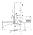
- a box-like enclosure has a front wall 11 in which there is a generally rectangular slot 14.
- a tray 13 of hollow, open-topped construction is slideable into and out of the enclosure through the slot 14. With the tray fully extended from the enclosure, i.e. fully open, bank notes are placed in it so that when the tray is pushed fully into the enclosure, i.e. fully closed, the bank notes are carried into the interior of the enclosure. By then operating a plunger (not shown) the bank notes can be displaced through the bottom of the tray, so that when the tray is again pulled out it is empty.
- WO 02/019289 for a clearer understanding of these features of the apparatus which will not therefore be further described.
- the tray 13 has a channel-shaped rear wall 20 and between this and the interior 21 of the tray where bank notes are to be placed is a compartment 22 in which a body 23 is located. This is mounted on a slotted shelf 24 enabling the body 23 to move backward and forward in the compartment 22 in a direction parallel with the direction in which the tray 13 is moveable.
- the body 23 is biased by a compression spring 25 to the forward position in which it is shown both in Figure 1 and Figure 2 .
- the body 23 is generally T-shaped and at its forward end has an upstanding flange 26 which will pass with close tolerance between pegs 27 and 28 depending from the top of the slot 14 as the tray 13 moves into or out of the enclosure.
- a latch member 29 is attached to the underside of the body 23 by a resilient strip 30 which, in an unstressed condition ( Figure 1 ) holds the latch 29 in a raised position.
- the channel 20 and the rear of the latch member 29 have cooperating cam surfaces 31 and 32.
- the front surface 33 of the latch is straight.
- the spring 25 will hold the body 23 in its forward position in the compartment 22.
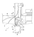
- the latch 29 is held in a raised position by the strip 30 and the tray 13 is free to slide through the slot 14 into and out of the enclosure ( Figure 1 ). If, however, with the tray pulled out an item such as the banknote 35 of Figure 2 has not been inserted properly into the compartment 21 of the tray and overlies the flange 26, then when the tray 13 is pushed into the enclosure the note 35 will jam between the pegs 27 and 28 and the flange 26, causing the latter to move back against the action of the spring 25.
Abstract
Description
- This invention relates to a safety device for a container of the kind comprising a housing, a slot in a wall of the housing and a tray slideable into and out of the housing through the slot to convey items placed in the tray while the tray is extended from the slot into the interior of the housing. An example of such a container is the apparatus for the storage and transport of bank notes described in the International Patent Application published as
WO 02/019289 - A problem which has been identified in use of the apparatus of
WO 02/019289 - A principal object of the present invention is to offer a solution to this problem. If a bank note is not fully inserted into the tray before the tray is pushed into the housing it will actuate a safety device which will prevent the tray from closing. Inability to close the tray will of course alert the user to the problem. After the tray has been pulled out again and the offending note or notes have been properly inserted into the tray the safety device is deactivated and it is possible to push the tray fully into the housing, whereupon the plunger can be operated.
- In accordance with the present invention there is provided a safety device for a container of the kind comprising a housing, a slot in a wall of the housing and a tray slideable into and out of the housing through the slot to convey items placed in the tray while the tray is extended from the slot into the interior of the housing, the safety device comprising a body mounted in the tray to have limited .movement relative thereto generally in the direction of movement of the tray, means biasing said body to a forward position in which, as the tray moves into the slot, it substantially fills the cross sectional area between the tray and the slot and a latch depending from the body, the latch having a camming surface which will cooperate with a camming surface of the tray to force the latch downward as the body moves rearwardly and a latch surface adapted to abut said wall below the slot, the arrangement being such that if the slot is obstructed when the tray is moved into the housing the body will be moved rearwardly by the obstruction to a position where the latch will engage said wall to prevent reception of the tray into the housing.
- The safety device may be applied to the apparatus described and claimed in the International Patent Application published as
WO 02/019289 - The body may have an upstanding flange in the region of its forward end which passes as a close tolerance fit between formations of the housing on opposite sides of the slot as the tray moves into the housing.
- Preferably the latch is connected to the body by connection means which biases the latch to a raised position. The connection means may be a strip of resilient material.
- Said camming surface of the tray may be a curved internal surface near to the rear of the tray and the camming surface of the latch may be a curved rear surface of the latch.
- A preferred embodiment of the invention will now be described by way of non-limitative example with reference to the accompanying drawings, in which:
- Figures 1
- is a partial sectional elevation through apparatus of the kind described and illustrated in
WO 02/019289 - Figure 2
- is a view similar to
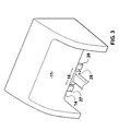
Figure 1 but showing the tray in a partially open position, and - Figure 3
- is a schematic, partial view taken in the direction of the arrow A in
Figure 2 . - A box-like enclosure has a
front wall 11 in which there is a generallyrectangular slot 14. Atray 13 of hollow, open-topped construction is slideable into and out of the enclosure through theslot 14. With the tray fully extended from the enclosure, i.e. fully open, bank notes are placed in it so that when the tray is pushed fully into the enclosure, i.e. fully closed, the bank notes are carried into the interior of the enclosure. By then operating a plunger (not shown) the bank notes can be displaced through the bottom of the tray, so that when the tray is again pulled out it is empty. Reference is made toWO 02/019289
Thetray 13 has a channel-shapedrear wall 20 and between this and theinterior 21 of the tray where bank notes are to be placed is acompartment 22 in which abody 23 is located. This is mounted on a slottedshelf 24 enabling thebody 23 to move backward and forward in thecompartment 22 in a direction parallel with the direction in which thetray 13 is moveable. Thebody 23 is biased by acompression spring 25 to the forward position in which it is shown both inFigure 1 andFigure 2 . Thebody 23 is generally T-shaped and at its forward end has anupstanding flange 26 which will pass with close tolerance betweenpegs slot 14 as thetray 13 moves into or out of the enclosure. - A
latch member 29 is attached to the underside of thebody 23 by aresilient strip 30 which, in an unstressed condition (Figure 1 ) holds thelatch 29 in a raised position. Thechannel 20 and the rear of thelatch member 29 have cooperatingcam surfaces front surface 33 of the latch is straight. - If the
flange 26 can pass freely between thepegs spring 25 will hold thebody 23 in its forward position in thecompartment 22. Thelatch 29 is held in a raised position by thestrip 30 and thetray 13 is free to slide through theslot 14 into and out of the enclosure (Figure 1 ). If, however, with the tray pulled out an item such as thebanknote 35 ofFigure 2 has not been inserted properly into thecompartment 21 of the tray and overlies theflange 26, then when thetray 13 is pushed into the enclosure thenote 35 will jam between thepegs flange 26, causing the latter to move back against the action of thespring 25. As this happens thecam surface 32 will be pressed against thecam surface 31, causing thelatch 29 to be deflected downwardly against the action of the strip 30 (Figure 2 ). As thetray 13 is pushed further into theslot 14 thesurface 33 of the latch will abut thewall 11 below theslot 14 arresting the movement of the tray. The user is thus alerted to misplacement of thenote 35 and must pull the tray out again to remove it. As theflange 26 moves away from thepegs body 23 is moved back to its forward position by thespring 25, raising thelatch 29. Provided there is no longer anything overlying theflange 26 the user can push thetray 13 fully into the enclosure (Figure 1 ) and the plunger can be operated to displace banknotes out of the tray.
Claims (6)
- A safety device for a container of the kind comprising a housing, a slot in a wall of the housing and a tray slideable into and out of the housing through the slot to convey items placed in the tray while the tray is extended from the slot into the interior of the housing, characterised in that the safety device comprises a body (23) mounted in the tray (13) to have limited .movement relative thereto generally in the .direction of movement of the tray, means (25) biasing said body to a forward position in which, as the tray moves into the slot, it substantially fills the cross sectional area between the tray and the slot and a latch (29) depending from the body, the latch having a camming surface (32) which will cooperate with a camming surface (31) of the tray to force the latch downward as the body moves rearwardly and a latch surface (33) adapted to abut said wall below the slot, the arrangement being such that if the slot (14) is obstructed when the tray (13) is moved into the housing the body (23) will be moved rearwardly by the obstruction to a position where the latch (29) will engage said wall (11) to prevent reception of the tray into the housing.
- A safety device as claimed in either preceding claim, characterised in that the body (23) has an upstanding flange (26) in the region of its forward end which passes as a close tolerance fit between formations (27,28) of the housing on opposite sides of the slot as the tray moves into the housing.
- A safety device as claimed in any one of the preceding claims, characterised in that the latch (29) is connected to the body (23) by connection means (30) which biases the latch to a raised position.
- A safety device as claimed in. claim 4, characterised in that the connection means is a strip (30) of resilient material.
- A safety device as claimed in any one of the preceding claims, characterised in that said camming surface of the tray is a curved internal surface (3.1) near to the rear of the tray.
- A safety device as claimed in any one of the preceding claims, characterised in that the camming surface of the latch is a curved rear surface (32) of the latch.
Applications Claiming Priority (2)
| Application Number | Priority Date | Filing Date | Title |
|---|---|---|---|
| GB0328393A GB2408830B (en) | 2003-12-06 | 2003-12-06 | Safety device for bank note storage apparatus |
| GB0328393 | 2003-12-06 |
Publications (3)
| Publication Number | Publication Date |
|---|---|
| EP1538575A2 EP1538575A2 (en) | 2005-06-08 |
| EP1538575A3 EP1538575A3 (en) | 2005-08-31 |
| EP1538575B1 true EP1538575B1 (en) | 2010-02-24 |
Family
ID=30129804
Family Applications (1)
| Application Number | Title | Priority Date | Filing Date |
|---|---|---|---|
| EP04257567A Not-in-force EP1538575B1 (en) | 2003-12-06 | 2004-12-06 | Safety device for bank note storage apparatus |
Country Status (5)
| Country | Link |
|---|---|
| US (1) | US7175067B2 (en) |
| EP (1) | EP1538575B1 (en) |
| AT (1) | ATE459065T1 (en) |
| DE (1) | DE602004025661D1 (en) |
| GB (1) | GB2408830B (en) |
Families Citing this family (1)
| Publication number | Priority date | Publication date | Assignee | Title |
|---|---|---|---|---|
| EP2778105B1 (en) * | 2013-03-11 | 2016-10-26 | Wincor Nixdorf International GmbH | Apparatus and method for filling a transport container with vouchers |
Family Cites Families (25)
| Publication number | Priority date | Publication date | Assignee | Title |
|---|---|---|---|---|
| US3500772A (en) * | 1969-01-27 | 1970-03-17 | George I Ratner | Security locking device |
| US3674360A (en) * | 1970-10-29 | 1972-07-04 | Automatic Close & Lock Corp | Security locking device |
| US3655186A (en) | 1970-12-14 | 1972-04-11 | Ardac Inc | Stacker for paper currency |
| GB1442599A (en) * | 1972-07-28 | 1976-07-14 | Armstrong J H G | Containers for substantially planar articles |
| GB2121472B (en) * | 1982-06-04 | 1985-09-18 | De La Rue Syst | Secure containers |
| GB2136498B (en) * | 1983-03-16 | 1986-07-09 | Burroughs Corp | Money cassette for an autoteller |
| US4512263A (en) | 1983-05-06 | 1985-04-23 | International Business Machines Corporation | Depository apparatus with sequential stacking |
| GB2199890A (en) | 1986-12-05 | 1988-07-20 | Timetill Security Ltd | A cassette for storage and transportation of banknotes |
| JPH0643083Y2 (en) | 1987-03-02 | 1994-11-09 | グローリー工業株式会社 | Currency storage device |
| GB8729306D0 (en) | 1987-12-16 | 1988-01-27 | De La Rue Syst | Closure assembly |
| IE880187L (en) * | 1988-01-26 | 1989-07-26 | Teneret Ltd | A security drawer apparatus |
| US4913341A (en) * | 1989-01-03 | 1990-04-03 | Bachman Theodore L | Currency storage device |
| GB2236143B (en) | 1989-09-06 | 1993-09-01 | Timothy William Tod | Bank note cassette |
| US5176315A (en) | 1990-07-30 | 1993-01-05 | The Highsmith Co., Inc. | Book receptacle with collapsible container |
| EP0674296A4 (en) | 1992-05-19 | 1996-06-05 | Ace Denken Kk | Paper money handling system for game houses. |
| US5595129A (en) | 1992-11-17 | 1997-01-21 | Grobe; Philip R. | Removable security box |
| US5344226A (en) * | 1993-03-12 | 1994-09-06 | Lee Wen Ting | Safety device for drawers |
| US6074646A (en) * | 1993-10-26 | 2000-06-13 | Board Of Regents, The University Of Texas System | Nondenatured HIV envelope antigens for detecting early HIV-specific antibodies |
| CZ283145B6 (en) | 1993-12-03 | 1998-01-14 | As Beteiligungs Gesellschaft M. B. H. | Apparatus for stacking and issuing banknotes |
| US5607102A (en) | 1995-12-11 | 1997-03-04 | Walsh; Michael J. | Tamper-resistant cash box |
| GB2313622B (en) * | 1996-05-31 | 1998-12-09 | Roger Winston Keith Painter | A bank note holder |
| US5850966A (en) * | 1996-07-16 | 1998-12-22 | Safepak, Inc. | Deposit retrieval and transport security apparatus |
| DE19640574C2 (en) * | 1996-10-01 | 1998-07-16 | Siemens Nixdorf Inf Syst | Note container for note issuing unit |
| US5890439A (en) | 1997-01-21 | 1999-04-06 | Mcgunn; Edward T. | Safe deposit box assembly |
| AU2001282346B2 (en) * | 2000-08-29 | 2005-07-28 | Volumatic Limited | Apparatus for the storage and transport of bank notes |
-
2003
- 2003-12-06 GB GB0328393A patent/GB2408830B/en not_active Expired - Lifetime
-
2004
- 2004-12-06 DE DE602004025661T patent/DE602004025661D1/en active Active
- 2004-12-06 US US11/005,364 patent/US7175067B2/en active Active
- 2004-12-06 EP EP04257567A patent/EP1538575B1/en not_active Not-in-force
- 2004-12-06 AT AT04257567T patent/ATE459065T1/en not_active IP Right Cessation
Also Published As
| Publication number | Publication date |
|---|---|
| GB0328393D0 (en) | 2004-01-14 |
| DE602004025661D1 (en) | 2010-04-08 |
| US7175067B2 (en) | 2007-02-13 |
| EP1538575A2 (en) | 2005-06-08 |
| ATE459065T1 (en) | 2010-03-15 |
| GB2408830B (en) | 2006-05-24 |
| EP1538575A3 (en) | 2005-08-31 |
| GB2408830A (en) | 2005-06-08 |
| US20050121502A1 (en) | 2005-06-09 |
Similar Documents
| Publication | Publication Date | Title |
|---|---|---|
| EP2458125B1 (en) | Cash box provided with self-locking mechanism | |
| US7909198B2 (en) | Tamper evident enclosure for the storage and transport of bank notes | |
| CN105314148B (en) | It is a kind of for load and be closed accommodate bank note disposable bags device | |
| JP5622245B2 (en) | Catch system | |
| DE602006015259D1 (en) | Apparatus for processing banknotes and control system therefor | |
| EP2953496B1 (en) | Magnetically operated locking slider for zipper | |
| EP2053572A2 (en) | Apparatus for receiving and storing banknotes | |
| US20040007165A1 (en) | Theft-prevention ink pack device, and treasure safe having the same | |
| JP6659432B2 (en) | Cabinet for disposal of confidential documents | |
| US4720611A (en) | Electro-manual drawer latch | |
| US7971775B2 (en) | Magnetic lock for banknote cassette | |
| EP1550625B1 (en) | Media dispenser comprising media cassette with internal lock | |
| EP1538575B1 (en) | Safety device for bank note storage apparatus | |
| US4377303A (en) | Closure latch mechanism improvements | |
| US6805344B2 (en) | Automatic bank note pushing device for a storing device | |
| JP2015013729A (en) | Cabinet for disposal of confidential document | |
| US4066308A (en) | Cash drawer | |
| EP2482258A1 (en) | Storage drawer for banknotes and valuables | |
| GB2313622A (en) | A bank note holder | |
| JP2008308313A (en) | Secret document discarding cabinet | |
| JP4950764B2 (en) | Stamping equipment | |
| JP3868165B2 (en) | Information processing device | |
| JPH09226434A (en) | Console box for vehicle | |
| JP3641158B2 (en) | Disk cartridge positioning structure in stocker | |
| KR100655409B1 (en) | Tray fixing device for car |
Legal Events
| Date | Code | Title | Description |
|---|---|---|---|
| PUAI | Public reference made under article 153(3) epc to a published international application that has entered the european phase |
Free format text: ORIGINAL CODE: 0009012 |
|
| AK | Designated contracting states |
Kind code of ref document: A2 Designated state(s): AT BE BG CH CY CZ DE DK EE ES FI FR GB GR HU IE IS IT LI LT LU MC NL PL PT RO SE SI SK TR |
|
| AX | Request for extension of the european patent |
Extension state: AL BA HR LV MK YU |
|
| PUAL | Search report despatched |
Free format text: ORIGINAL CODE: 0009013 |
|
| AK | Designated contracting states |
Kind code of ref document: A3 Designated state(s): AT BE BG CH CY CZ DE DK EE ES FI FR GB GR HU IE IS IT LI LT LU MC NL PL PT RO SE SI SK TR |
|
| AX | Request for extension of the european patent |
Extension state: AL BA HR LV MK YU |
|
| 17P | Request for examination filed |
Effective date: 20060110 |
|
| AKX | Designation fees paid |
Designated state(s): AT BE BG CH CY CZ DE DK EE ES FI FR GB GR HU IE IS IT LI LT LU MC NL PL PT RO SE SI SK TR |
|
| 17Q | First examination report despatched |
Effective date: 20060808 |
|
| GRAP | Despatch of communication of intention to grant a patent |
Free format text: ORIGINAL CODE: EPIDOSNIGR1 |
|
| GRAS | Grant fee paid |
Free format text: ORIGINAL CODE: EPIDOSNIGR3 |
|
| GRAA | (expected) grant |
Free format text: ORIGINAL CODE: 0009210 |
|
| AK | Designated contracting states |
Kind code of ref document: B1 Designated state(s): AT BE BG CH CY CZ DE DK EE ES FI FR GR HU IE IS IT LI LT LU MC NL PL PT RO SE SI SK TR |
|
| REG | Reference to a national code |
Ref country code: CH Ref legal event code: EP |
|
| REG | Reference to a national code |
Ref country code: IE Ref legal event code: FG4D |
|
| REF | Corresponds to: |
Ref document number: 602004025661 Country of ref document: DE Date of ref document: 20100408 Kind code of ref document: P |
|
| REG | Reference to a national code |
Ref country code: NL Ref legal event code: VDEP Effective date: 20100224 |
|
| LTIE | Lt: invalidation of european patent or patent extension |
Effective date: 20100224 |
|
| PG25 | Lapsed in a contracting state [announced via postgrant information from national office to epo] |
Ref country code: IS Free format text: LAPSE BECAUSE OF FAILURE TO SUBMIT A TRANSLATION OF THE DESCRIPTION OR TO PAY THE FEE WITHIN THE PRESCRIBED TIME-LIMIT Effective date: 20100624 Ref country code: LT Free format text: LAPSE BECAUSE OF FAILURE TO SUBMIT A TRANSLATION OF THE DESCRIPTION OR TO PAY THE FEE WITHIN THE PRESCRIBED TIME-LIMIT Effective date: 20100224 Ref country code: PT Free format text: LAPSE BECAUSE OF FAILURE TO SUBMIT A TRANSLATION OF THE DESCRIPTION OR TO PAY THE FEE WITHIN THE PRESCRIBED TIME-LIMIT Effective date: 20100625 |
|
| PG25 | Lapsed in a contracting state [announced via postgrant information from national office to epo] |
Ref country code: SI Free format text: LAPSE BECAUSE OF FAILURE TO SUBMIT A TRANSLATION OF THE DESCRIPTION OR TO PAY THE FEE WITHIN THE PRESCRIBED TIME-LIMIT Effective date: 20100224 Ref country code: AT Free format text: LAPSE BECAUSE OF FAILURE TO SUBMIT A TRANSLATION OF THE DESCRIPTION OR TO PAY THE FEE WITHIN THE PRESCRIBED TIME-LIMIT Effective date: 20100224 Ref country code: PL Free format text: LAPSE BECAUSE OF FAILURE TO SUBMIT A TRANSLATION OF THE DESCRIPTION OR TO PAY THE FEE WITHIN THE PRESCRIBED TIME-LIMIT Effective date: 20100224 Ref country code: FI Free format text: LAPSE BECAUSE OF FAILURE TO SUBMIT A TRANSLATION OF THE DESCRIPTION OR TO PAY THE FEE WITHIN THE PRESCRIBED TIME-LIMIT Effective date: 20100224 |
|
| PG25 | Lapsed in a contracting state [announced via postgrant information from national office to epo] |
Ref country code: EE Free format text: LAPSE BECAUSE OF FAILURE TO SUBMIT A TRANSLATION OF THE DESCRIPTION OR TO PAY THE FEE WITHIN THE PRESCRIBED TIME-LIMIT Effective date: 20100224 Ref country code: BE Free format text: LAPSE BECAUSE OF FAILURE TO SUBMIT A TRANSLATION OF THE DESCRIPTION OR TO PAY THE FEE WITHIN THE PRESCRIBED TIME-LIMIT Effective date: 20100224 Ref country code: SE Free format text: LAPSE BECAUSE OF FAILURE TO SUBMIT A TRANSLATION OF THE DESCRIPTION OR TO PAY THE FEE WITHIN THE PRESCRIBED TIME-LIMIT Effective date: 20100224 Ref country code: RO Free format text: LAPSE BECAUSE OF FAILURE TO SUBMIT A TRANSLATION OF THE DESCRIPTION OR TO PAY THE FEE WITHIN THE PRESCRIBED TIME-LIMIT Effective date: 20100224 Ref country code: NL Free format text: LAPSE BECAUSE OF FAILURE TO SUBMIT A TRANSLATION OF THE DESCRIPTION OR TO PAY THE FEE WITHIN THE PRESCRIBED TIME-LIMIT Effective date: 20100224 Ref country code: GR Free format text: LAPSE BECAUSE OF FAILURE TO SUBMIT A TRANSLATION OF THE DESCRIPTION OR TO PAY THE FEE WITHIN THE PRESCRIBED TIME-LIMIT Effective date: 20100525 Ref country code: ES Free format text: LAPSE BECAUSE OF FAILURE TO SUBMIT A TRANSLATION OF THE DESCRIPTION OR TO PAY THE FEE WITHIN THE PRESCRIBED TIME-LIMIT Effective date: 20100604 Ref country code: CY Free format text: LAPSE BECAUSE OF FAILURE TO SUBMIT A TRANSLATION OF THE DESCRIPTION OR TO PAY THE FEE WITHIN THE PRESCRIBED TIME-LIMIT Effective date: 20100224 |
|
| PG25 | Lapsed in a contracting state [announced via postgrant information from national office to epo] |
Ref country code: SK Free format text: LAPSE BECAUSE OF FAILURE TO SUBMIT A TRANSLATION OF THE DESCRIPTION OR TO PAY THE FEE WITHIN THE PRESCRIBED TIME-LIMIT Effective date: 20100224 Ref country code: CZ Free format text: LAPSE BECAUSE OF FAILURE TO SUBMIT A TRANSLATION OF THE DESCRIPTION OR TO PAY THE FEE WITHIN THE PRESCRIBED TIME-LIMIT Effective date: 20100224 Ref country code: BG Free format text: LAPSE BECAUSE OF FAILURE TO SUBMIT A TRANSLATION OF THE DESCRIPTION OR TO PAY THE FEE WITHIN THE PRESCRIBED TIME-LIMIT Effective date: 20100524 |
|
| PLBE | No opposition filed within time limit |
Free format text: ORIGINAL CODE: 0009261 |
|
| STAA | Information on the status of an ep patent application or granted ep patent |
Free format text: STATUS: NO OPPOSITION FILED WITHIN TIME LIMIT |
|
| PG25 | Lapsed in a contracting state [announced via postgrant information from national office to epo] |
Ref country code: DK Free format text: LAPSE BECAUSE OF FAILURE TO SUBMIT A TRANSLATION OF THE DESCRIPTION OR TO PAY THE FEE WITHIN THE PRESCRIBED TIME-LIMIT Effective date: 20100224 |
|
| 26N | No opposition filed |
Effective date: 20101125 |
|
| PG25 | Lapsed in a contracting state [announced via postgrant information from national office to epo] |
Ref country code: IT Free format text: LAPSE BECAUSE OF FAILURE TO SUBMIT A TRANSLATION OF THE DESCRIPTION OR TO PAY THE FEE WITHIN THE PRESCRIBED TIME-LIMIT Effective date: 20100224 |
|
| PG25 | Lapsed in a contracting state [announced via postgrant information from national office to epo] |
Ref country code: MC Free format text: LAPSE BECAUSE OF NON-PAYMENT OF DUE FEES Effective date: 20101231 |
|
| REG | Reference to a national code |
Ref country code: CH Ref legal event code: PL |
|
| REG | Reference to a national code |
Ref country code: FR Ref legal event code: ST Effective date: 20110831 |
|
| PG25 | Lapsed in a contracting state [announced via postgrant information from national office to epo] |
Ref country code: FR Free format text: LAPSE BECAUSE OF NON-PAYMENT OF DUE FEES Effective date: 20110103 Ref country code: LI Free format text: LAPSE BECAUSE OF NON-PAYMENT OF DUE FEES Effective date: 20101231 Ref country code: CH Free format text: LAPSE BECAUSE OF NON-PAYMENT OF DUE FEES Effective date: 20101231 Ref country code: IE Free format text: LAPSE BECAUSE OF NON-PAYMENT OF DUE FEES Effective date: 20101206 |
|
| REG | Reference to a national code |
Ref country code: DE Ref legal event code: R119 Ref document number: 602004025661 Country of ref document: DE Effective date: 20110701 |
|
| PG25 | Lapsed in a contracting state [announced via postgrant information from national office to epo] |
Ref country code: DE Free format text: LAPSE BECAUSE OF NON-PAYMENT OF DUE FEES Effective date: 20110701 |
|
| PG25 | Lapsed in a contracting state [announced via postgrant information from national office to epo] |
Ref country code: LU Free format text: LAPSE BECAUSE OF NON-PAYMENT OF DUE FEES Effective date: 20101206 Ref country code: HU Free format text: LAPSE BECAUSE OF FAILURE TO SUBMIT A TRANSLATION OF THE DESCRIPTION OR TO PAY THE FEE WITHIN THE PRESCRIBED TIME-LIMIT Effective date: 20100825 |
|
| PG25 | Lapsed in a contracting state [announced via postgrant information from national office to epo] |
Ref country code: TR Free format text: LAPSE BECAUSE OF FAILURE TO SUBMIT A TRANSLATION OF THE DESCRIPTION OR TO PAY THE FEE WITHIN THE PRESCRIBED TIME-LIMIT Effective date: 20100224 |