EP1538570A2 - Method for graphically displaying audio frequency component in digital broadcast receiver - Google Patents
Method for graphically displaying audio frequency component in digital broadcast receiver Download PDFInfo
- Publication number
- EP1538570A2 EP1538570A2 EP04028754A EP04028754A EP1538570A2 EP 1538570 A2 EP1538570 A2 EP 1538570A2 EP 04028754 A EP04028754 A EP 04028754A EP 04028754 A EP04028754 A EP 04028754A EP 1538570 A2 EP1538570 A2 EP 1538570A2
- Authority
- EP
- European Patent Office
- Prior art keywords
- audio
- frequency
- data
- mpeg
- audio data
- Prior art date
- Legal status (The legal status is an assumption and is not a legal conclusion. Google has not performed a legal analysis and makes no representation as to the accuracy of the status listed.)
- Withdrawn
Links
Images


Classifications
-
- G—PHYSICS
- G06—COMPUTING OR CALCULATING; COUNTING
- G06T—IMAGE DATA PROCESSING OR GENERATION, IN GENERAL
- G06T13/00—Animation
- G06T13/20—Three-dimensional [3D] animation
- G06T13/205—Three-dimensional [3D] animation driven by audio data
-
- H—ELECTRICITY
- H04—ELECTRIC COMMUNICATION TECHNIQUE
- H04N—PICTORIAL COMMUNICATION, e.g. TELEVISION
- H04N5/00—Details of television systems
- H04N5/44—Receiver circuitry for the reception of television signals according to analogue transmission standards
- H04N5/60—Receiver circuitry for the reception of television signals according to analogue transmission standards for the sound signals
-
- G—PHYSICS
- G06—COMPUTING OR CALCULATING; COUNTING
- G06T—IMAGE DATA PROCESSING OR GENERATION, IN GENERAL
- G06T11/00—Two-dimensional [2D] image generation
- G06T11/20—Drawing from basic elements
- G06T11/26—Drawing of charts or graphs
-
- H—ELECTRICITY
- H04—ELECTRIC COMMUNICATION TECHNIQUE
- H04H—BROADCAST COMMUNICATION
- H04H60/00—Arrangements for broadcast applications with a direct linking to broadcast information or broadcast space-time; Broadcast-related systems
- H04H60/56—Arrangements characterised by components specially adapted for monitoring, identification or recognition covered by groups H04H60/29-H04H60/54
- H04H60/58—Arrangements characterised by components specially adapted for monitoring, identification or recognition covered by groups H04H60/29-H04H60/54 of audio
-
- H—ELECTRICITY
- H04—ELECTRIC COMMUNICATION TECHNIQUE
- H04N—PICTORIAL COMMUNICATION, e.g. TELEVISION
- H04N17/00—Diagnosis, testing or measuring for television systems or their details
-
- H—ELECTRICITY
- H04—ELECTRIC COMMUNICATION TECHNIQUE
- H04N—PICTORIAL COMMUNICATION, e.g. TELEVISION
- H04N21/00—Selective content distribution, e.g. interactive television or video on demand [VOD]
- H04N21/40—Client devices specifically adapted for the reception of or interaction with content, e.g. set-top-box [STB]; Operations thereof
- H04N21/43—Processing of content or additional data, e.g. demultiplexing additional data from a digital video stream; Elementary client operations, e.g. monitoring of home network or synchronising decoder's clock; Client middleware
- H04N21/431—Generation of visual interfaces for content selection or interaction; Content or additional data rendering
-
- H—ELECTRICITY
- H04—ELECTRIC COMMUNICATION TECHNIQUE
- H04N—PICTORIAL COMMUNICATION, e.g. TELEVISION
- H04N21/00—Selective content distribution, e.g. interactive television or video on demand [VOD]
- H04N21/40—Client devices specifically adapted for the reception of or interaction with content, e.g. set-top-box [STB]; Operations thereof
- H04N21/43—Processing of content or additional data, e.g. demultiplexing additional data from a digital video stream; Elementary client operations, e.g. monitoring of home network or synchronising decoder's clock; Client middleware
- H04N21/432—Content retrieval operation from a local storage medium, e.g. hard-disk
- H04N21/4325—Content retrieval operation from a local storage medium, e.g. hard-disk by playing back content from the storage medium
-
- H—ELECTRICITY
- H04—ELECTRIC COMMUNICATION TECHNIQUE
- H04N—PICTORIAL COMMUNICATION, e.g. TELEVISION
- H04N21/00—Selective content distribution, e.g. interactive television or video on demand [VOD]
- H04N21/40—Client devices specifically adapted for the reception of or interaction with content, e.g. set-top-box [STB]; Operations thereof
- H04N21/43—Processing of content or additional data, e.g. demultiplexing additional data from a digital video stream; Elementary client operations, e.g. monitoring of home network or synchronising decoder's clock; Client middleware
- H04N21/439—Processing of audio elementary streams
- H04N21/4394—Processing of audio elementary streams involving operations for analysing the audio stream, e.g. detecting features or characteristics in audio streams
-
- H—ELECTRICITY
- H04—ELECTRIC COMMUNICATION TECHNIQUE
- H04N—PICTORIAL COMMUNICATION, e.g. TELEVISION
- H04N21/00—Selective content distribution, e.g. interactive television or video on demand [VOD]
- H04N21/40—Client devices specifically adapted for the reception of or interaction with content, e.g. set-top-box [STB]; Operations thereof
- H04N21/41—Structure of client; Structure of client peripherals
- H04N21/426—Internal components of the client ; Characteristics thereof
Definitions
- the present invention relates to a method for graphically displaying an audio frequency component in a digital broadcast receiver, and more particularly to a method for extracting a frequency component of an audio stream in a digital broadcast receiver such as a Set Top Box (STB), and graphically displaying the extracted frequency component of the audio stream.
- STB Set Top Box
- the above-mentioned digital broadcast receiver includes a tuner 10, a demultiplexer (DeMux) 11, an audio buffer 12, a video buffer 13, a data buffer 14, an MPEG decoder 15, a microprocessor 16, an OSD generator 17, and a memory, as shown in Fig. 1.
- a tuner 10 a demultiplexer (DeMux) 11, an audio buffer 12, a video buffer 13, a data buffer 14, an MPEG decoder 15, a microprocessor 16, an OSD generator 17, and a memory, as shown in Fig. 1.
- the microprocessor 16 selects a corresponding broadcast channel by controlling the tuner 10, and divides a data stream received over the selected broadcast channel into audio data, video data, and other data, etc., by controlling the demultiplexer 11.
- the MPEG decoder 15 reads data temporarily stored in the audio buffer 12, the video buffer 13, and the data buffer 14, and decodes the read data into original video and audio data.
- the OSD generator 17 Upon receiving a control signal from the microprocessor 16, the OSD generator 17 generates a variety of information message images or menu images to be displayed on a screen of an external device such as a TV.
- the microprocessor 16 controls a signal-processed audio signal decoded by the MPEG decoder 15 to be outputted via a speaker of the TV, and controls the OSD generator 17 to generate a caption-, blue-colored background-, or still- image including an information message indicative of audio broadcast channel as shown in Fig. 2, such that the generated image is displayed on the TV screen.
- a user of the digital broadcast receiver selects a desired broadcast channel, and views audio and video signals received over the selected broadcast channel. If the user selects an audio broadcast channel, the user can listen to an audio signal received over the selected audio broadcast channel.
- a conventional digital broadcast receiver receives audio data over the audio broadcast channel, a blue-colored background image including an information message indicative of the audio broadcast channel is displayed on the TV screen, such that the user is not visually stimulated, and feels monotonous.
- a hardware module or complicated calculation process is necessary to extract a frequency component using PCM audio data having been decoded. Therefore, there has been no digital broadcast receiver capable of graphically displaying components for every frequency band of an audio stream when a broadcast program having no image data, for example, a radio broadcast program or a music broadcast program, is received.
- the present invention has been made in view of the above problems, and it is an object of the present invention to provide a method for efficiently extracting a frequency component of an audio stream input in a state of being encoded in a digital broadcast receiver such as an STB, and graphically displaying the extracted frequency component of the audio stream.
- a method for graphically displaying an audio frequency component in a digital broadcast receiver comprising the steps of: a) extracting a plurality of frequency-band components associated with an audio stream during a decoding process of the audio stream; and b) generating graphic data corresponding to the extracted frequency-band components, and displaying the graphic data on a screen.
- the audio stream is indicative of any one of MPEG-1 audio data, MPEG-2 audio data, and Dolby AC-3 audio data.
- the audio stream is received over a broadcast channel, or is received from an MPEG-based reproducer contained in the digital broadcast receiver.
- the frequency-band components of the MPEG-1 audio data or the frequency-band components of the MPEG-2 audio data are extracted in a filter bank operation of the decoding process.
- the frequency-band components of the Dolby AC-3 audio data are extracted in an inverse transform operation of the decoding process.
- the number of extracted frequency bands is adjusted through a predetermined calculation among the frequency-band components separated in the decoding process.
- the extracted frequency-band components are temporarily stored in a register having a plurality of sections classified according to individual frequency bands, such that the stored frequency-band components are used to generate a corresponding graphic image.
- caption data including information associated with the audio stream is displayed along with the graphic data corresponding to the frequency-band components.
- Fig. 3 is a block diagram illustrating a configuration for implementing a graphic display method of an audio frequency component in accordance with the present invention.
- an input stream may be indicative of a data stream including audio and/or video data received over a broadcast channel, or may also be indicative of an audio stream input from an MP3 player contained in a digital broadcast receiver.
- the audio stream is input in a state of being compressed by a voice compression algorithm.
- voice compression algorithms for example, MPEG-1 Layer 1, Layer 2, Layer 3, MPEG-2 AAC, and Dolby AC-3 algorithms, etc.
- the above-mentioned voice compression algorithms are adapted to convert audio data into frequency-domain data.
- a procedure for inversely converting the frequency-domain encoded audio data into time-domain data In order to reproduce the input audio data, there is needed a procedure for inversely converting the frequency-domain encoded audio data into time-domain data.
- the present invention stores an audio frequency component used in the above-mentioned procedure for inversely converting the frequency-domain data into the time-domain data in a register or predetermined memory, and enables an external device to refer to the stored audio frequency component.
- the audio decoder shown in Fig. 3 inversely converts the input audio stream into time-domain data, and at the same time detects component values for every frequency band of the audio stream at intervals of a predetermined time (e.g., 10 times per second), such that it stores the detected component values in a register or memory.
- the microprocessor reads the audio frequency component stored in the register at intervals of the predetermined time, and controls the OSD generator to generate a bar-shaped graph corresponding to the audio frequency component.
- the graph generated by the OSD generator is combined with a video image reproduced by a video decoder, and the resultant graph is displayed on an external display such as a TV. If video data is not contained in the input stream in Fig. 3, a still image including the bar-shaped graph generated by the OSD generator is displayed on the external display without displaying a video image.
- Fig. 4 is a flow chart illustrating a method for extracting an audio frequency component when receiving an audio stream based on the MPEG-1 Layer 3 standard in accordance with a preferred embodiment of the present invention.
- the MPEG-1 compression algorithm divides audio data into 32 frequency-domain data units, and compresses the divided frequency-domain data units according to auditory characteristics of a human being.
- a decoding process uses an Inverse Modified Discrete Cosine Transform (IMDCT) scheme and a synthesis filter bank such that it synthesizes audio data from the 32 frequency components.
- IMDCT Inverse Modified Discrete Cosine Transform
- the demultiplexer 11 When receiving the audio stream based on the MPEG-1 Layer 3 standard, the demultiplexer 11 divides the received audio stream into audio data, side information data, and scale factor data.
- the audio data is temporarily stored in the audio buffer 13, is Huffman-decoded at step 150, and is dequantized at step 151, such that its scale is adjusted by the decoded scale factor information at step 155. Also, the side information decoded at step 156 controls audio data dequantization and a scale operation of the audio data.
- the above-mentioned scale-controlled audio data is transmitted to an IMDCT 153 and an Up-sampling & Synthesis filter bank 154, such that frequency-domain audio data is converted into time-domain audio data.
- the decoded side information data controls an IMDCT operation of the audio data.
- component values for every frequency band of the audio data are transmitted to a register 20.
- the register 20 separately stores the frequency-band component values divided by the synthesis filter bank process 154. For example, if the audio data is indicative of MPEG-1 Layer 3 audio data, individual component values of 32 frequency-domains are stored separately from each other in the register 20.
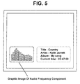
- the microprocessor 16 checks audio frequency component values stored in the register 20 at intervals of a predetermined time, controls the OSD generator 17 to generate a graphic image associated with the audio frequency component values as shown in Fig. 5, and displays the generated graphic image on a TV screen.
- the microprocessor 16 searches for audio information (e.g., an audio file name, a singer name, and lyrics, etc.) provided over an audio broadcast channel, controls the OSD generator 17 to generate caption data including the audio information in the form of text as shown in Fig. 5, and displays the caption data on the TV screen. Therefore, the user views graphic image associated with audio frequency components and the caption data of audio data displayed on the TV screen, and at the same time listens to the audio data.
- audio information e.g., an audio file name, a singer name, and lyrics, etc.
- the inventive signal processing procedure capable of extracting a plurality of frequency-band components separately in the decoding process of the audio data is considered to be more effective.
- Fig. 6 is a flow chart illustrating a method for extracting an audio frequency component when receiving an audio stream based on the MPEG-2 AAC (Advanced Audio Coding) standard in accordance with another preferred embodiment of the present invention.
- the MPEG-2 AAC audio data is sequentially transmitted to a noiseless decoding unit 251, a dequantizer 252, a scale factor 253, a middle/side stereo 244, a prediction unit 255, an intensity coupling unit 256, a temporal noise shaping unit 257, a filter bank 258, and a pre-processing unit 259 as shown in Fig. 6, such that PCM audio data is generated.
- the filter bank process 154 a plurality of frequency-band component values associated with audio data are separately transmitted to the register 20.
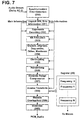
- Fig. 7 is a flow chart illustrating a method for extracting an audio frequency component when receiving an audio stream based on the Dolby AC-3 standard in accordance with yet another preferred embodiment of the present invention.
- the Dolby AC-3 audio data is sequentially transmitted to a synchronization error detection unit 350, an Unpack Side Information unit 351, an exponent decoding unit 352, a bit allocation unit 353, a dequantizer 354, a decoupling unit 355, a rematrixing unit 356, a dynamic range compression unit 357, an Inverse Transform unit 358, a window overlap/add unit 359, and a downmix unit 360 as shown in Fig. 7, such that PCM audio data is generated.
- the Dolby AC-3 audio stream is characterized in that it converts 512 audio samples into 256 frequency samples, instead of using a sub-band filter bank.
- a plurality of frequency-band component values of audio data are transmitted to the register 20, respectively.
- the register 20 stores 256 frequency-band component values separately from each other.
- the microprocessor 16 checks audio frequency component values temporarily stored in the register, controls the OSD generator 17 to generate a graphic image associated with the audio frequency component values as shown in Fig. 5, and displays the graphic image on the TV screen.
- the microprocessor 16 searches for audio information provided over an audio broadcast channel, controls the OSD generator 17 to generate caption data in the form of text, and displays the caption data on the TV screen. Therefore, the user views graphic image associated with audio frequency components and the caption data of audio data displayed on the TV screen, and at the same time listens to the audio data.
- the present invention can efficiently extract a frequency component of an encoded audio stream.
- the present invention extracts the frequency component of the audio stream during a decoding process of the audio stream, such that it prevents the size of a device from being increased and also prevents additional power consumption from being generated.
- the present invention allows a user to graphically view a frequency component of audio data on a TV screen, simultaneously with listening to the audio data.
Landscapes
- Engineering & Computer Science (AREA)
- Multimedia (AREA)
- Signal Processing (AREA)
- Physics & Mathematics (AREA)
- General Physics & Mathematics (AREA)
- Theoretical Computer Science (AREA)
- Health & Medical Sciences (AREA)
- Biomedical Technology (AREA)
- General Health & Medical Sciences (AREA)
- Acoustics & Sound (AREA)
- Databases & Information Systems (AREA)
- Circuits Of Receivers In General (AREA)
- Two-Way Televisions, Distribution Of Moving Picture Or The Like (AREA)
Abstract
Description
Claims (10)
- A method for graphically displaying an audio frequency component in a digital broadcast receiver, comprising the steps of:a) extracting a plurality of frequency-band components associated with an audio stream during a decoding process of the audio stream; andb) generating graphic data corresponding to the extracted frequency-band components, and displaying the graphic data on a screen.
- The method according to claim 1, wherein the audio stream is indicative of any one of MPEG-1 audio data, MPEG-2 audio data, and Dolby AC-3 audio data.
- The method according to claim 2, wherein the frequency-band components of the MPEG-1 audio data or the frequency-band components of the MPEG-2 audio data are extracted in a filter bank operation of the decoding process.
- The method according to claim 2, the frequency-band components of the Dolby AC-3 audio data are extracted in an inverse transform operation of the decoding process.
- The method according to claim 1, wherein the extracting step a) further includes the step of:adjusting the number of frequency bands through a predetermined calculation among the frequency-band components separated by the decoding process.
- The method according to claim 1, wherein the extracted frequency-band components are temporarily stored in a register having a plurality of sections classified according to individual frequency bands.
- The method according to claim 1, wherein the displaying step b) further includes the step of:generating caption data including information associated with the audio stream, and displaying the caption data on the screen.
- The method according to claim 1, wherein the audio stream is received over a broadcast channel.
- The method according to claim 1, wherein the audio stream is input from an MPEG-based reproducer contained in the digital broadcast receiver.
- The method according to claim 9, wherein the MPEG-based reproducer is indicative of an MP3 player.
Applications Claiming Priority (2)
| Application Number | Priority Date | Filing Date | Title |
|---|---|---|---|
| KR2003087823 | 2003-12-05 | ||
| KR1020030087823A KR100568775B1 (en) | 2003-12-05 | 2003-12-05 | How to Display Audio Graphic Equalizer in Digital Broadcast Receiver |
Publications (2)
| Publication Number | Publication Date |
|---|---|
| EP1538570A2 true EP1538570A2 (en) | 2005-06-08 |
| EP1538570A3 EP1538570A3 (en) | 2005-08-31 |
Family
ID=34464808
Family Applications (1)
| Application Number | Title | Priority Date | Filing Date |
|---|---|---|---|
| EP04028754A Withdrawn EP1538570A3 (en) | 2003-12-05 | 2004-12-03 | Method for graphically displaying audio frequency component in digital broadcast receiver |
Country Status (4)
| Country | Link |
|---|---|
| US (1) | US20050132397A1 (en) |
| EP (1) | EP1538570A3 (en) |
| KR (1) | KR100568775B1 (en) |
| CN (1) | CN1625239A (en) |
Cited By (2)
| Publication number | Priority date | Publication date | Assignee | Title |
|---|---|---|---|---|
| EP2048801A1 (en) * | 2007-10-11 | 2009-04-15 | Promax Electronica, S.A. | Method for identifying and diagnosing interferences in RF signals and particularly television signals |
| ES2324693A1 (en) * | 2007-10-11 | 2009-08-12 | Promax Electronica, S.A. | Metod and apparatus for the identification and diagnosis of interferences in rf signs, in particular television signals. (Machine-translation by Google Translate, not legally binding) |
Families Citing this family (3)
| Publication number | Priority date | Publication date | Assignee | Title |
|---|---|---|---|---|
| KR100852223B1 (en) * | 2006-02-03 | 2008-08-13 | 한국전자통신연구원 | Apparatus and method for visualizing multichannel audio signals |
| KR100803606B1 (en) * | 2006-09-05 | 2008-02-15 | 삼성전자주식회사 | Display method of equalizer and recording medium thereof |
| CN103793190A (en) * | 2014-02-07 | 2014-05-14 | 北京京东方视讯科技有限公司 | Information display method and device and display equipment |
Family Cites Families (7)
| Publication number | Priority date | Publication date | Assignee | Title |
|---|---|---|---|---|
| US4461026A (en) * | 1980-01-21 | 1984-07-17 | Motorola Inc. | Radio with audio graphic equalizer |
| US4665494A (en) * | 1982-12-17 | 1987-05-12 | Victor Company Of Japan, Limited | Spectrum display device for audio signals |
| JPS61264576A (en) * | 1985-05-18 | 1986-11-22 | Pioneer Electronic Corp | Control system for segment display device in tape deck |
| JPH01296169A (en) * | 1988-05-24 | 1989-11-29 | Sony Corp | Spectrum analyzer |
| US6430533B1 (en) * | 1996-05-03 | 2002-08-06 | Lsi Logic Corporation | Audio decoder core MPEG-1/MPEG-2/AC-3 functional algorithm partitioning and implementation |
| US6230322B1 (en) * | 1997-11-05 | 2001-05-08 | Sony Corporation | Music channel graphical user interface |
| US20030187528A1 (en) * | 2002-04-02 | 2003-10-02 | Ke-Chiang Chu | Efficient implementation of audio special effects |
-
2003
- 2003-12-05 KR KR1020030087823A patent/KR100568775B1/en not_active Expired - Fee Related
-
2004
- 2004-12-03 EP EP04028754A patent/EP1538570A3/en not_active Withdrawn
- 2004-12-03 US US11/002,721 patent/US20050132397A1/en not_active Abandoned
- 2004-12-06 CN CNA2004100979189A patent/CN1625239A/en active Pending
Cited By (3)
| Publication number | Priority date | Publication date | Assignee | Title |
|---|---|---|---|---|
| EP2048801A1 (en) * | 2007-10-11 | 2009-04-15 | Promax Electronica, S.A. | Method for identifying and diagnosing interferences in RF signals and particularly television signals |
| ES2324693A1 (en) * | 2007-10-11 | 2009-08-12 | Promax Electronica, S.A. | Metod and apparatus for the identification and diagnosis of interferences in rf signs, in particular television signals. (Machine-translation by Google Translate, not legally binding) |
| ES2324693B1 (en) * | 2007-10-11 | 2010-07-07 | Promax Electronica, S.A. | METHOD AND APPLIANCE FOR THE IDENTIFICATION AND DIAGNOSIS OF INTERFERENCES IN RF SIGNALS, IN PARTICULAR TELEVISION SIGNALS. |
Also Published As
| Publication number | Publication date |
|---|---|
| CN1625239A (en) | 2005-06-08 |
| US20050132397A1 (en) | 2005-06-16 |
| KR20050054504A (en) | 2005-06-10 |
| KR100568775B1 (en) | 2006-04-07 |
| EP1538570A3 (en) | 2005-08-31 |
Similar Documents
| Publication | Publication Date | Title |
|---|---|---|
| US7467088B2 (en) | Closed caption control apparatus and method therefor | |
| KR101761041B1 (en) | Metadata for loudness and dynamic range control | |
| JP5101579B2 (en) | Spatial audio parameter display | |
| KR101061129B1 (en) | Method of processing audio signal and apparatus thereof | |
| JP5414684B2 (en) | Method and apparatus for performing audio watermarking, watermark detection, and watermark extraction | |
| US20100189266A1 (en) | Method and an apparatus for processing an audio signal | |
| KR100998913B1 (en) | Method of processing audio signal and apparatus thereof | |
| US20090325524A1 (en) | method and an apparatus for processing an audio signal | |
| WO2008039045A1 (en) | Apparatus for processing mix signal and method thereof | |
| US20160065160A1 (en) | Terminal device and audio signal output method thereof | |
| TW201012246A (en) | A method and an apparatus for processing an audio signal | |
| US20050004791A1 (en) | Perceptual noise substitution | |
| EP1538570A2 (en) | Method for graphically displaying audio frequency component in digital broadcast receiver | |
| KR20090110234A (en) | Audio signal processing method and device thereof | |
| JP2006050045A (en) | Moving image data editing apparatus and moving image data editing method | |
| JP2006093918A (en) | Digital broadcast receiving apparatus, digital broadcast receiving method, digital broadcast receiving program, and program recording medium | |
| JP2000341652A (en) | Hearing compensation method for digital broadcasting and receiving apparatus used therefor | |
| JP2011118215A (en) | Coding device, coding method, program and electronic apparatus | |
| EP2357645A1 (en) | Music detecting apparatus and music detecting method | |
| JP2000152398A (en) | Audio signal processor and method | |
| HK40013898B (en) | Metadata for loudness and dynamic range control | |
| KR20070008232A (en) | Digital Multimedia Speed Control Device and Method | |
| JP2008016882A (en) | Display device, display control method, and display control program | |
| JP2011138123A (en) | Music detecting device and music detecting method |
Legal Events
| Date | Code | Title | Description |
|---|---|---|---|
| PUAI | Public reference made under article 153(3) epc to a published international application that has entered the european phase |
Free format text: ORIGINAL CODE: 0009012 |
|
| AK | Designated contracting states |
Kind code of ref document: A2 Designated state(s): AT BE BG CH CY CZ DE DK EE ES FI FR GB GR HU IE IS IT LI LT LU MC NL PL PT RO SE SI SK TR |
|
| AX | Request for extension of the european patent |
Extension state: AL BA HR LV MK YU |
|
| PUAL | Search report despatched |
Free format text: ORIGINAL CODE: 0009013 |
|
| AK | Designated contracting states |
Kind code of ref document: A3 Designated state(s): AT BE BG CH CY CZ DE DK EE ES FI FR GB GR HU IE IS IT LI LT LU MC NL PL PT RO SE SI SK TR |
|
| AX | Request for extension of the european patent |
Extension state: AL BA HR LV MK YU |
|
| RIC1 | Information provided on ipc code assigned before grant |
Ipc: 7H 04H 1/00 B Ipc: 7G 01R 23/18 B Ipc: 7G 06T 15/70 A |
|
| 17P | Request for examination filed |
Effective date: 20060228 |
|
| AKX | Designation fees paid |
Designated state(s): DE FR GB |
|
| STAA | Information on the status of an ep patent application or granted ep patent |
Free format text: STATUS: THE APPLICATION IS DEEMED TO BE WITHDRAWN |
|
| 18D | Application deemed to be withdrawn |
Effective date: 20061024 |