EP1538568A2 - X-ray CT system and image processing method - Google Patents
X-ray CT system and image processing method Download PDFInfo
- Publication number
- EP1538568A2 EP1538568A2 EP04257483A EP04257483A EP1538568A2 EP 1538568 A2 EP1538568 A2 EP 1538568A2 EP 04257483 A EP04257483 A EP 04257483A EP 04257483 A EP04257483 A EP 04257483A EP 1538568 A2 EP1538568 A2 EP 1538568A2
- Authority
- EP
- European Patent Office
- Prior art keywords
- ray
- tomographic images
- subject
- images
- image
- Prior art date
- Legal status (The legal status is an assumption and is not a legal conclusion. Google has not performed a legal analysis and makes no representation as to the accuracy of the status listed.)
- Withdrawn
Links
Images




Classifications
-
- A—HUMAN NECESSITIES
- A61—MEDICAL OR VETERINARY SCIENCE; HYGIENE
- A61B—DIAGNOSIS; SURGERY; IDENTIFICATION
- A61B6/00—Apparatus or devices for radiation diagnosis; Apparatus or devices for radiation diagnosis combined with radiation therapy equipment
- A61B6/02—Arrangements for diagnosis sequentially in different planes; Stereoscopic radiation diagnosis
- A61B6/03—Computed tomography [CT]
-
- G—PHYSICS
- G06—COMPUTING OR CALCULATING; COUNTING
- G06T—IMAGE DATA PROCESSING OR GENERATION, IN GENERAL
- G06T19/00—Manipulating three-dimensional [3D] models or images for computer graphics
-
- G—PHYSICS
- G06—COMPUTING OR CALCULATING; COUNTING
- G06T—IMAGE DATA PROCESSING OR GENERATION, IN GENERAL
- G06T12/00—Tomographic reconstruction from projections
- G06T12/30—Image post-processing, e.g. metal artefact correction
Definitions
- the present invention relates to an X-ray CT system and image processing method. More particularly, the present invention is concerned with an X-ray CT system and image processing method for producing second tomographic images, which represent sections different from sections represented by first tomographic images, using the first tomographic images produced from projection data.
- CT X-ray computed tomography
- the X-ray CT system includes an X-ray source and an X-ray detector array opposed to the X-ray source with a subject between them.
- the X-ray detector array detects X-rays irradiated from the X-ray source to the subject.
- the X-ray CT system scans the subject by rotating the X-ray source about the subject and moving the X-ray source. This results in a plurality of views of projection data of the subject.
- the X-ray CT system recomposes the acquired projection data so as to produce tomographic images of a predetermined slice thickness representing sections at predetermined positions of the subject.
- the X-ray CT system produces tomographic images of sections orthogonal to the direction of a body axis linking the subject's head and the subject's tiptoe.
- the tomographic images are called axial images.
- an X-ray CT system in accordance with the present invention comprises an X-ray source and an X-ray detector array opposed to the X-ray source with a subject between them.
- the X-ray detector array detects X-rays irradiated from the X-ray source to the subject.
- the X-ray source is rotated about the subject and moved, whereby first tomographic images of a predetermined slice thickness representing sections that are orthogonal to a body axis, which links the subject's head and the subject's tiptoe, at predetermined positions of the subject are produced.
- the image processing method further comprises: a step of designating parameters that define the conditions for producing second tomographic images, which represent predetermined sections parallel to the body axis, from the first tomographic images; and a step of producing the second tomographic images from the plurality of first tomographic images according to the parameters.
- the second tomographic images are produced from the plurality of first tomographic images.
- images to be used for diagnosis can be produced for a short period of time and the number of images to be used for diagnosis can be reduced.
- images to be used for diagnosis can be produced for a short period of time and the number of images to be used for diagnosis can be reduced.
- Fig. 1 is a block diagram showing the overall configuration of an X-ray CT system in accordance with the present invention.
- an X-ray CT system 1 comprises a scanner gantry 2, an operator console 3, and a radiographic table (cradle) 4.
- the scanner gantry 2 includes an X-ray tube 21, a collimator 22, a detector array 23, a data acquisition unit 24, an X-ray controller 25, and a collimator controller 26.
- the X-ray tube 21 radiates X-rays. X-rays radiated from the X-ray tube 21 are recomposed into, for example, a fan-shaped X-ray beam by a collimator 22 and irradiated to the detector array 23.
- An example of an X-ray source included in the present invention corresponds to the X-ray tube 21.
- the detector array 23 has a plurality of X-ray detector elements set in array in a direction in which the fan-beam X-rays spread.
- the detector array 23 is a multi-channel detector having the plurality of X-ray detector elements set in array.
- An example of an X-ray detector included in the present invention corresponds to the detector array 23.
- the detector array 23 forms an X-ray incidence surface curved like a semicylindrical concave surface as a whole.
- the detector array 23 comprises combinations of, for example, a scintillator and a photodiode.
- the X-ray detector elements are not limited to the combinations but may be realized with semiconductor X-ray detector elements that utilize cadmium telluride (CdTe) or the like or ionization chamber-type X-ray detector elements that utilize a xenon gas.
- the detector array 23 is connected to the data acquisition unit 24.
- the X-ray controller 25 controls X-irradiation from the X-ray tube 21.
- the collimator controller 26 controls the collimator 22.
- connectional relationship between the X-ray tube 21 and X-ray controller 25 and the connectional relationship between the collimator 22 and collimator controller 26 will be omitted.
- the X-ray tube 21, collimator 22, detector array 23, data acquisition unit 24, X-ray controller 25, and collimator controller 26 are incorporated in a rotary unit 27 of the scanner gantry 2.
- a subject lies down on a cradle in a bore 29 located in the center of the rotary unit 2.
- the rotary unit 27 rotates while being controlled by the rotation controller 28.
- the X-ray tube 21 irradiates X-rays
- the detector array 23 detects X-rays, which have passed through the subject, as projection information of each view.
- the illustration of the connection between the rotary unit 27 and rotation controller 28 will be omitted.
- the operator console 3 includes a central processing unit 31, an input device 32, a display device 33, and a storage device 34.
- the central processing unit 31 comprises, for example, a microprocessor and a memory.
- Tomographic image information and other information sent from the central processing unit 31 are displayed on the display device 33.
- a user manipulates the input device 32, whereby various kinds of instructions or pieces of information are transferred to the central processing unit 31.
- Fig. 2 is a side view of the X-ray CT system 1 in accordance with the present invention.
- the scanner gantry 2 that moves based on manipulations performed at the operator console 3 causes the X-ray tube 21 and detector array 23 to relatively move.
- the X-ray tube 21 and detector array 23 move near the subject lying down on the radiographic table 4, and thus scan a region of the subject that is an object of detection.
- the data acquisition unit 24 acquires projection data from the subject, and transmits the projection data to the central processing unit 31.
- the central processing unit 31 reconstructs images of axial sections orthogonal to a body axis linking the subject's head and the subject's tiptoe.
- the images shall be called axial images and correspond to first tomographic images employed in the present invention.
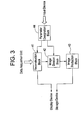
- Fig. 3 is a block diagram illustratively showing the central processing unit 31 included in the X-ray CT system 1.
- the parameter designation block 44 designates parameters, based on which axial images are produced from projection data, in response to a command entered at the input device 32 by a user.
- the parameters to be designated include, for example, a slice thickness, a scan field of a subject, a field of view (FOV), a window width (W/W) indicating a range of CT numbers to be selected, and a window level (W/L) indicating a median of the range of CT numbers to be selected.
- a parameter designating means included in the present invention corresponds to the parameter designation block 44.
- Fig. 4 is a schematic sectional view showing a section represented by an axial image produced by the reconstruction block 41.
- a section represented by an axial image is an xy plane
- a section represented by a sagittal image is a yz plane
- a section represented by a coronal image is an xz plane.
- the sagittal section and coronal section are sections parallel to the body axis.
- Tomographic images of the sagittal section and coronal section shall be called the sagittal image and coronal image respectively.
- An example of a second tomographic image employed in the present invention corresponds to at least one of the sagittal image and coronal image.
- the parameter designation block 44 designates a range of movement of the scanner gantry 2 and a magnitude of X-irradiation.
- the parameter designation block 44 transmits the designated parameters to each of the reconstruction block 41 and image division block 42.
- the parameters are designated prior to radiography of a subject.
- the image production block 43 concatenates a plurality of axial images, each of which is divided into the predetermined fields by the image division block 42, so as to produce images that develop in the z-axis direction corresponding to the body-axis direction. For concatenation, the image production block 43 interpolates the division fields in the z-axis direction if necessary so as to produce the images. Moreover, the image production block 43 averages the sum of pixel data items contained in each of the division fields of each of the axial images. The averages are also added up in the z-axis direction. Consequently, sagittal images or coronal images are produced.
- An example of an image processing means included in the present invention corresponds to the image division block 42 and image production block 43.
- parameters based on which axial images are produced are designated, parameters based on which sagittal images or coronal images are produced are also designated. Consequently, when the axial images are produced, sagittal images or coronal images are produced from the axial images according to the designated parameters by following a series of steps. Moreover, when the sagittal images or coronal images are produced, since a slick thickness can be designated in advance, an unnecessarily large number of images will not be produced. Eventually, the number of images a user has to interpret can be reduced.
- Fig. 5 is a flowchart describing the actions to be performed in the X-ray CT system 1 in accordance with the present invention.
- a user uses the input device 32 to enter a scanning range, a slice thickness for axial images, a field of view (FOV), a window width (W/W), a window level (W/L), a slice thickness for sagittal or coronal images, and a range of image production.
- FOV field of view
- W/W window width
- W/L window level
- ST1 slice thickness for sagittal or coronal images
- ST1 the conditions for radiography and the conditions for image processing are designated in the parameter designation block 44 included in the central processing unit 31 (ST1).
- Fig. 6 shows an example of a parameter designation screen image via which parameters based on which sagittal images or coronal images are produced are designated.
- right and left lateral distances (R200 and L200) from an isocenter and a slice thickness (TH 10) are designated as the conditions for producing sagittal images.
- Anterior and posterior distances (A100 and P100) from the isocenter and a slice thickness (TH 10) are designated as the conditions for producing coronal images.
- the right and left lateral distances from the isocenter or the anterior and posterior distances therefrom define the range of image production.
- the number of pixels constituting each axial image may be designated on behalf of the slice thickness.
- a user asks a subject to lie down on the radiographic table 4. Thereafter, the user uses the input device 32 to issue a command to the central processing unit 31.
- the central processing unit 31 moves the scanner gantry 2 while rotating the rotary unit 27, and allows the X-ray tube 21 to irradiate X-rays.
- the subject is scanned (ST2).
- the detector array 23 detects X-rays having passed through the subject, and the data acquisition unit 24 acquires a view of projection data.
- the data acquisition unit 24 transmits the acquired projection data to the central processing unit 31.
- the parameters including the scanning range may be designated at step ST1. Thereafter, the subject may be scanned at step ST2.
- the reconstruction block 41 included in the central processing unit 31 uses the projection data to execute image reconstruction and thus produces axial images. Moreover, the reconstruction block 41 transmits the produced axial images to the display device 33. If necessary, the reconstruction block 41 transmits the produced axial images to the storage device 34.
- the produced axial images are displayed on the display device 33, and stored in the storage device 34 (ST4).
- the user views the axial images displayed on the display device 33 and confirms that the images representing the scanning range have been produced (ST5). If the images of the scanning range have not been produced or if the scanning range must be modified, processing may be resumed from step ST1 or step ST2.
- the central processing unit 31 continues image processing. Sagittal images and coronal images are produced based on axial images (ST7).
- Fig. 7 includes schematic views illustratively showing part of the sagittal image production step.
- the reconstruction block 41 transmits image data of produced axial images ax1 to ax5 to the image division block 42.
- the axial images ax1 to ax5 have been produced based on a slice thickness for axial images designated in the parameter designation block 44.
- the number of axial images to be transmitted to the image division block 42 is not limited to five.
- the image division block 42 divides each of the axial images ax1 to ax5 in parallel with the y axis into division fields b1 to b3 within the range defined with the designated right and left lateral distances (R200 and L200) from an isocenter IC according to the parameters designated in order to produce sagittal images.
- the width w1 of each of the division fields b1 to b3 corresponds to a slice thickness for sagittal images designated in the parameter designation block 44.
- the image division block 42 adds up in the x-axis direction the pixel data items, which are represented by the same y-coordinate, among all the pixel data items contained in the division field b1 of the axial image ax1 developed on the xy plane. Furthermore, the image division block 42 averages the sum of the pixel data items. Thus, pixel data items lined in the y-axis direction are produced.
- the image division block 42 performs the above processing on each of the division fields b1 to b3 of the axial image ax1.
- the resultant pixel data items are transmitted to the image production block 43.
- pixel data corresponds to a CT number or a luminance value exhibited by each pixel.
- the image production block 43 concatenates in the z-axis direction the pixel data items, which are calculated by averaging each of the sums of the pixel data items contained in the division field b1 of each of the axial images ax1 to ax5, so as to produce a sagittal image sa1.
- a distance between the centers of adjoining ones of the axial images ax1 to ax5 may be smaller than the slice thickness for axial images, that is, adjoining ones of the axial images ax1 to ax5 may overlap.
- the image production block 43 does not use one of overlapping images when producing the sagittal image sa1.
- the image production block 43 interpolates in the z-axis direction the data items calculated from the respective division fields so as to produce the sagittal image sa1.
- the image production unit 43 transmits the produced sagittal images sa1 to sa3 to each of the display device 33 and storage device 34.
- Fig. 8 includes schematic views illustratively showing part of the coronal image production step.
- the coronal image production step is substantially identical to the foregoing sagittal image production step. Only a difference will be described below.
- the reconstruction block 41 transmits data items of the plurality of axial images ax1 to ax5 to the image division block 42.
- the axial images ax1 to ax5 are produced based on the slice thickness designated in the parameter designation block 44.
- the image division block 52 divides each of the axial images ax1 to ax5 in parallel with the x axis into division fields c1 to c3 within the range defined with the designated anterior and posterior distances (A100 and P100) from the isocenter IC according to the parameters designated as listed in Fig. 6.
- the width w2 of each of the division fields corresponds to the slice thickness designated in the parameter designation block 41.
- the image division block 42 adds up in the y-axis direction the pixel data items contained in each of the division fields of each of the axial images ax1 to ax5, and averages the sum.
- the image division block 42 then transmits the resultant data to the image production block 43.
- the image production block 43 transmits the produced coronal images to each of the display device 33 and storage device 34.
- sagittal images and coronal images are produced from the axial images by following a series of steps according to the parameters.
- a slice thickness can be designated in advance. An unnecessarily large number of images will therefore not be produced.
- the time required from radiography to interpretation can be shortened.
- images can be readily preserved and sorted out.
- a radiography system in accordance with the present invention is not limited to the X-ray CT system of the aforesaid embodiment.
- the X-ray CT system in accordance with the present invention produces both sagittal images and coronal images
- one of the sagittal images and coronal images may be produced.
- the number of images and the scanning range are taken for instance and may be modified.
- images of any sections other than the sagittal and coronal sections can be produced.
Landscapes
- Engineering & Computer Science (AREA)
- Physics & Mathematics (AREA)
- General Physics & Mathematics (AREA)
- Theoretical Computer Science (AREA)
- Health & Medical Sciences (AREA)
- Life Sciences & Earth Sciences (AREA)
- Medical Informatics (AREA)
- Computer Graphics (AREA)
- General Engineering & Computer Science (AREA)
- Computer Hardware Design (AREA)
- Software Systems (AREA)
- Pathology (AREA)
- Heart & Thoracic Surgery (AREA)
- Nuclear Medicine, Radiotherapy & Molecular Imaging (AREA)
- Optics & Photonics (AREA)
- Biophysics (AREA)
- Radiology & Medical Imaging (AREA)
- Biomedical Technology (AREA)
- High Energy & Nuclear Physics (AREA)
- Molecular Biology (AREA)
- Surgery (AREA)
- Animal Behavior & Ethology (AREA)
- General Health & Medical Sciences (AREA)
- Public Health (AREA)
- Veterinary Medicine (AREA)
- Apparatus For Radiation Diagnosis (AREA)
Abstract
Description
Claims (10)
- An X-ray CT system (1) which includes an X-ray source (21) and an X-ray detector (23) opposed to said X-ray source (21) with a subject between them, said X-ray detector (23) detecting X-rays irradiated from said X-ray source (21) to said subject, and said X-ray source (21) being rotated about said subject and moved in order to produce a plurality of first tomographic images representing sections that are orthogonal to a body axis, which links said subject's head and said subject's tiptop, at predetermined positions of said subject,
said X-ray CT system (1) comprising:a parameter designating device (32) for designating conditions for producing second tomographic images that represent predetermined sections parallel to said body axis; andan image processing device (31) for producing said second tomographic images from said plurality of first tomographic images according to said parameters. - An X-ray CT system (1) according to Claim 1, wherein:said parameter designating device (32) designates a range of production, based on which said second tomographic images are produced, in said first tomographic images or said subject, and also designates a slice thickness for said second tomographic images produced based on the range of production; andsaid image processing device (31) comprises: an image division block that divides each of said first tomographic images into a plurality of division fields according to the designated slice thickness; and an image production block that produces said second tomographic images by performing image processing of concatenating said division fields of said plurality of first tomographic images in a body-axis direction.
- An X-ray CT system (1) according to Claim 2, wherein in said image processing device (31), said image division block adds up pixel data items contained in each of said division fields, and said image production block produces said second tomographic images by concatenating in the body-axis direction said division fields of said plurality of first tomographic images.
- An X-ray CT system (1) according to Claim 3, wherein in said image processing device (31), said image division block calculates averages of the sums of pixel data items contained in each of said division fields of each of said first tomographic images, and said image production block produces said second tomographic images by concatenating said division fields of said plurality of first tomographic images, of which pixel data items are added up and averaged, in the body-axis direction.
- An X-ray CT system (1) according to any of Claims 1 to 4, wherein in said image processing device (31), said image production block interpolates corresponding division fields in the body-axis direction so as to produce said second tomographic images.
- An X-ray CT system (1) according to Claim 2, wherein in said image processing device (31), said image division block adds up pixel data items, which are contained in each of said division fields of each of said first tomographic images, in a direction orthogonal to a direction in which each of said first tomographic images is divided.
- An X-ray CT system (1) according to Claim 2, wherein said parameter designating device (32) has the range of production, based on which said second tomographic images are produced, designated therein relative to the isocenter in said subject.
- An X-ray CT system (1) according to Claim 2, wherein said parameter designating device (32) has the range of production, based on which said second tomographic images are produced, designated therein relative to a position at which said subject is located.
- An X-ray CT system (1) according to Claim 1, wherein said image processing device (31) produces said second tomographic images representing sagittal sections or coronal sections.
- An image processing method that is implemented in an X-ray CT system (1) including an X-ray source (21) and an X-ray detector (23) opposed to said X-ray source (21) with a subject between them, and that comprises a step of scanning said subject by detecting X-rays irradiated from said X-ray source (21) to said subject with said X-ray detector (23) and rotating said X-ray source (21) about said subject and moving said X-ray source (21), and a step of producing first tomographic images representing sections that are orthogonal to a body axis, which links said subject's head and said subject's tiptoe, at predetermined positions of said subject,
said image processing method comprising the steps of:designating parameters that define conditions for producing second tomographic images, which represent predetermined sections parallel to said body axis, from said first tomographic images; andproducing said second tomographic images from said plurality of first tomographic images according to said parameters.
Applications Claiming Priority (2)
| Application Number | Priority Date | Filing Date | Title |
|---|---|---|---|
| JP2003403186A JP4056968B2 (en) | 2003-12-02 | 2003-12-02 | X-ray CT apparatus and image processing method |
| JP2003403186 | 2003-12-02 |
Publications (2)
| Publication Number | Publication Date |
|---|---|
| EP1538568A2 true EP1538568A2 (en) | 2005-06-08 |
| EP1538568A3 EP1538568A3 (en) | 2010-07-28 |
Family
ID=34463955
Family Applications (1)
| Application Number | Title | Priority Date | Filing Date |
|---|---|---|---|
| EP04257483A Withdrawn EP1538568A3 (en) | 2003-12-02 | 2004-12-01 | X-ray CT system and image processing method |
Country Status (5)
| Country | Link |
|---|---|
| US (1) | US7428289B2 (en) |
| EP (1) | EP1538568A3 (en) |
| JP (1) | JP4056968B2 (en) |
| KR (1) | KR20050053332A (en) |
| CN (1) | CN100415172C (en) |
Families Citing this family (1)
| Publication number | Priority date | Publication date | Assignee | Title |
|---|---|---|---|---|
| CN112183551A (en) * | 2019-07-02 | 2021-01-05 | 佳能株式会社 | Illumination color prediction method, image processing apparatus, and storage medium |
Family Cites Families (29)
| Publication number | Priority date | Publication date | Assignee | Title |
|---|---|---|---|---|
| JP4054402B2 (en) * | 1997-04-25 | 2008-02-27 | 株式会社東芝 | X-ray tomography equipment |
| US4472822A (en) * | 1980-05-19 | 1984-09-18 | American Science And Engineering, Inc. | X-Ray computed tomography using flying spot mechanical scanning mechanism |
| US5493595A (en) * | 1982-02-24 | 1996-02-20 | Schoolman Scientific Corp. | Stereoscopically displayed three dimensional medical imaging |
| US4680709A (en) * | 1984-11-13 | 1987-07-14 | General Electric Company | Back projection image reconstruction apparatus and method |
| US4737921A (en) * | 1985-06-03 | 1988-04-12 | Dynamic Digital Displays, Inc. | Three dimensional medical image display system |
| JPH01121038A (en) | 1987-11-06 | 1989-05-12 | Toshiba Corp | Image diagnosis system |
| US5295488A (en) | 1992-08-05 | 1994-03-22 | General Electric Company | Method and apparatus for projecting diagnostic images from volumed diagnostic data |
| US5442672A (en) * | 1993-03-31 | 1995-08-15 | Bjorkholm; Paul J. | Three-dimensional reconstruction based on a limited number of X-ray projections |
| DE69529857T2 (en) * | 1994-03-25 | 2004-01-08 | Kabushiki Kaisha Toshiba, Kawasaki | Radiotherapy System |
| JPH07265300A (en) | 1994-03-29 | 1995-10-17 | Toshiba Corp | Diagnostic support device |
| JP3853392B2 (en) | 1995-02-21 | 2006-12-06 | 東芝医用システムエンジニアリング株式会社 | Medical image processing apparatus for tomographic images |
| GB9515446D0 (en) | 1995-07-27 | 1995-09-27 | Marconi Gec Ltd | Imaging systems |
| US5754618A (en) * | 1995-12-22 | 1998-05-19 | Matsushita Electric Industrial | Image processing apparatus and image processing method for favorably enhancing continuous boundaries which are affected by noise |
| JP3828967B2 (en) * | 1996-10-30 | 2006-10-04 | 株式会社東芝 | X-ray CT scanner |
| US5802134A (en) | 1997-04-09 | 1998-09-01 | Analogic Corporation | Nutating slice CT image reconstruction apparatus and method |
| US6167110A (en) | 1997-11-03 | 2000-12-26 | General Electric Company | High voltage x-ray and conventional radiography imaging apparatus and method |
| JP4497570B2 (en) * | 1998-01-22 | 2010-07-07 | 株式会社東芝 | Diagnostic imaging equipment |
| US6292530B1 (en) * | 1999-04-29 | 2001-09-18 | General Electric Company | Method and apparatus for reconstructing image data acquired by a tomosynthesis x-ray imaging system |
| DE19962666A1 (en) * | 1999-12-23 | 2001-07-05 | Siemens Ag | Method for reconstructing 3D image data relating to a volume of interest of an examination object |
| DE10194962T1 (en) * | 2000-11-24 | 2003-12-04 | Nihon University Tokio Tokyo | Image processing method |
| WO2002043007A1 (en) * | 2000-11-25 | 2002-05-30 | Infinitt Co., Ltd. | 3-dimensional multiplanar reformatting system and method and computer-readable recording medium having 3-dimensional multiplanar reformatting program recorded thereon |
| US6526117B1 (en) * | 2001-11-09 | 2003-02-25 | Ge Medical Systems Global Technology Company, Llc | Method and apparatus to minimize phase misregistration artifacts in gated CT images |
| US6922457B2 (en) * | 2001-11-29 | 2005-07-26 | Kabushiki Kaisha Toshiba | Computer tomography apparatus |
| DE102004031169A1 (en) * | 2004-06-28 | 2006-01-19 | Siemens Ag | X-ray apparatus for determining image data of human or animal subject, has two-part filter dividing X-ray fan beam into two adjacent X-ray beam fans, each differing in intensity and comprising common boundary |
| JP2003190145A (en) | 2001-12-21 | 2003-07-08 | Ge Medical Systems Global Technology Co Llc | X-ray ct system and control method therefor |
| US7103134B2 (en) * | 2001-12-28 | 2006-09-05 | Kabushiki Kaisha Toshiba | Computed tomography apparatus |
| US7027855B2 (en) * | 2002-08-27 | 2006-04-11 | General Electric Company | R-peak detection corrections for improved cardiac gated reconstruction |
| JP4420312B2 (en) * | 2002-12-04 | 2010-02-24 | 株式会社東芝 | X-ray computed tomography apparatus and image processing apparatus |
| JP4434698B2 (en) * | 2003-11-13 | 2010-03-17 | 株式会社東芝 | X-ray CT system |
-
2003
- 2003-12-02 JP JP2003403186A patent/JP4056968B2/en not_active Expired - Fee Related
-
2004
- 2004-11-30 US US10/999,251 patent/US7428289B2/en not_active Expired - Fee Related
- 2004-12-01 EP EP04257483A patent/EP1538568A3/en not_active Withdrawn
- 2004-12-01 KR KR1020040099802A patent/KR20050053332A/en not_active Withdrawn
- 2004-12-02 CN CNB2004100980627A patent/CN100415172C/en not_active Expired - Fee Related
Also Published As
| Publication number | Publication date |
|---|---|
| CN1623512A (en) | 2005-06-08 |
| US7428289B2 (en) | 2008-09-23 |
| JP2005160712A (en) | 2005-06-23 |
| KR20050053332A (en) | 2005-06-08 |
| JP4056968B2 (en) | 2008-03-05 |
| CN100415172C (en) | 2008-09-03 |
| US20050117695A1 (en) | 2005-06-02 |
| EP1538568A3 (en) | 2010-07-28 |
Similar Documents
| Publication | Publication Date | Title |
|---|---|---|
| US7466790B2 (en) | Systems and methods for improving a resolution of an image | |
| US20060291612A1 (en) | X-ray CT method and X-ray CT apparatus | |
| US8798353B2 (en) | Apparatus and method for two-view tomosynthesis imaging | |
| US7072437B2 (en) | Radiation tomography system and tomography method | |
| US20100172472A1 (en) | Collecting images for image stitching with rotating a radiation detector | |
| JP3897925B2 (en) | Cone beam CT system | |
| US20220071578A1 (en) | Improved method of acquiring a radiographic scan of a region-of-interest in a metal containing object | |
| US7822171B2 (en) | Cone beam computed tomography with multiple partial scanning trajectories | |
| WO2007072286A2 (en) | Method for movement compensation of image data | |
| US7336758B2 (en) | Radiography system | |
| EP2029021A2 (en) | Systems and methods for determining object position | |
| CN101175439B (en) | Continuous computer tomography performing ultra-short scans and stronger weighting of up-to-date data | |
| US6728331B1 (en) | Method and system for trauma application of CT imaging | |
| US11158093B2 (en) | Workstation, medical imaging device including same, and control method therefor | |
| CN104545962B (en) | The medical imaging procedure and system of artifact in image can be reduced | |
| US7428289B2 (en) | X-ray CT system and image processing method | |
| JP2007125174A (en) | Radiographic imaging method and apparatus | |
| WO2006090321A1 (en) | Determination of the coverage of a ct scan | |
| EP3648062B1 (en) | Workstation, medical imaging device including same, and control method therefor | |
| JPH0921876A (en) | Improved gamma camera imaging system | |
| JP7258474B2 (en) | X-ray CT device and radiotherapy system | |
| EP3113111B1 (en) | Display of depth location of computed tomography slice images relative to an object to be imaged | |
| JPWO2019064346A1 (en) | Medical X-ray image processing device |
Legal Events
| Date | Code | Title | Description |
|---|---|---|---|
| PUAI | Public reference made under article 153(3) epc to a published international application that has entered the european phase |
Free format text: ORIGINAL CODE: 0009012 |
|
| AK | Designated contracting states |
Kind code of ref document: A2 Designated state(s): AT BE BG CH CY CZ DE DK EE ES FI FR GB GR HU IE IS IT LI LT LU MC NL PL PT RO SE SI SK TR |
|
| AX | Request for extension of the european patent |
Extension state: AL BA HR LV MK YU |
|
| PUAL | Search report despatched |
Free format text: ORIGINAL CODE: 0009013 |
|
| AK | Designated contracting states |
Kind code of ref document: A3 Designated state(s): AT BE BG CH CY CZ DE DK EE ES FI FR GB GR HU IE IS IT LI LT LU MC NL PL PT RO SE SI SK TR |
|
| AX | Request for extension of the european patent |
Extension state: AL BA HR LV MK YU |
|
| RIC1 | Information provided on ipc code assigned before grant |
Ipc: G06T 17/40 20060101ALI20100621BHEP Ipc: G06T 11/00 20060101AFI20050310BHEP |
|
| AKY | No designation fees paid | ||
| REG | Reference to a national code |
Ref country code: DE Ref legal event code: R108 Effective date: 20110309 Ref country code: DE Ref legal event code: 8566 |
|
| STAA | Information on the status of an ep patent application or granted ep patent |
Free format text: STATUS: THE APPLICATION IS DEEMED TO BE WITHDRAWN |
|
| 18D | Application deemed to be withdrawn |
Effective date: 20110129 |