EP1538433B1 - Capteur capacitif pour pneumatique et méthode de montage - Google Patents
Capteur capacitif pour pneumatique et méthode de montage Download PDFInfo
- Publication number
- EP1538433B1 EP1538433B1 EP04106127A EP04106127A EP1538433B1 EP 1538433 B1 EP1538433 B1 EP 1538433B1 EP 04106127 A EP04106127 A EP 04106127A EP 04106127 A EP04106127 A EP 04106127A EP 1538433 B1 EP1538433 B1 EP 1538433B1
- Authority
- EP
- European Patent Office
- Prior art keywords
- connector block
- capacitor
- capacitor plates
- rod
- sensor
- Prior art date
- Legal status (The legal status is an assumption and is not a legal conclusion. Google has not performed a legal analysis and makes no representation as to the accuracy of the status listed.)
- Expired - Fee Related
Links
- 238000000034 method Methods 0.000 title claims description 13
- 239000003990 capacitor Substances 0.000 claims description 54
- 125000006850 spacer group Chemical group 0.000 claims description 25
- 239000000463 material Substances 0.000 claims description 24
- 230000002093 peripheral effect Effects 0.000 claims description 23
- 239000004033 plastic Substances 0.000 claims description 6
- 229920003023 plastic Polymers 0.000 claims description 6
- 150000001875 compounds Chemical class 0.000 description 9
- 229910001369 Brass Inorganic materials 0.000 description 6
- 239000010951 brass Substances 0.000 description 6
- 229920002799 BoPET Polymers 0.000 description 4
- 239000005041 Mylar™ Substances 0.000 description 4
- 238000004519 manufacturing process Methods 0.000 description 4
- 239000004677 Nylon Substances 0.000 description 3
- 238000001746 injection moulding Methods 0.000 description 3
- 238000005259 measurement Methods 0.000 description 3
- 239000002184 metal Substances 0.000 description 3
- 229910052751 metal Inorganic materials 0.000 description 3
- 229920001778 nylon Polymers 0.000 description 3
- 238000004073 vulcanization Methods 0.000 description 3
- 230000000295 complement effect Effects 0.000 description 2
- 239000000203 mixture Substances 0.000 description 2
- 239000000088 plastic resin Substances 0.000 description 2
- 239000012815 thermoplastic material Substances 0.000 description 2
- RYGMFSIKBFXOCR-UHFFFAOYSA-N Copper Chemical compound [Cu] RYGMFSIKBFXOCR-UHFFFAOYSA-N 0.000 description 1
- 230000000712 assembly Effects 0.000 description 1
- 238000000429 assembly Methods 0.000 description 1
- 238000005452 bending Methods 0.000 description 1
- 238000003490 calendering Methods 0.000 description 1
- 238000010276 construction Methods 0.000 description 1
- 229910052802 copper Inorganic materials 0.000 description 1
- 239000010949 copper Substances 0.000 description 1
- 230000007547 defect Effects 0.000 description 1
- 239000012777 electrically insulating material Substances 0.000 description 1
- 238000010348 incorporation Methods 0.000 description 1
- 229910001092 metal group alloy Inorganic materials 0.000 description 1
- 150000002739 metals Chemical class 0.000 description 1
- 238000000465 moulding Methods 0.000 description 1
- 230000000717 retained effect Effects 0.000 description 1
- 238000005476 soldering Methods 0.000 description 1
Images


Classifications
-
- G—PHYSICS
- G01—MEASURING; TESTING
- G01L—MEASURING FORCE, STRESS, TORQUE, WORK, MECHANICAL POWER, MECHANICAL EFFICIENCY, OR FLUID PRESSURE
- G01L1/00—Measuring force or stress, in general
- G01L1/14—Measuring force or stress, in general by measuring variations in capacitance or inductance of electrical elements, e.g. by measuring variations of frequency of electrical oscillators
- G01L1/142—Measuring force or stress, in general by measuring variations in capacitance or inductance of electrical elements, e.g. by measuring variations of frequency of electrical oscillators using capacitors
Definitions
- the present invention relates to stress sensors for measuring stress forces within a material like a rubber compound and, more specifically, to a stress sensor and method of assembly for measuring stress forces present within a rubber compound of a tire.
- Capacitor sensors for measuring stress forces within materials are generally well known. Such sensors comprise metallic plates typically formed of a suitable material such as brass. The metallic plates are spaced apart by an air gap and are retained at a predisposed relationship. The metallic plates deflect responsive to stress force within a material and the air gap between the plates varies accordingly. As the air gap varies, the capacitance between the capacitor plates also varies. A signal is directed into the device from a remote source and the capacitance between the metallic sheets is detected by a remote antenna and reader to measure the level of stress force within the material.
- capacitor sensors work well and have been well accepted in the industry, several shortcomings in their manufacture and use remain.
- Existing capacitor stress sensors are relatively complicated to manufacture and assemble, resulting in a greater than optimal cost to the end user.
- existing sensors are prone to misalignment resulting in measurement inaccuracy.
- existing sensors tend to be susceptible to horizontal and vertical slippage between the capacitor plates when vulcanized into rubber compounds such as a tire. Such slippage distorts the configuration of the sensor and may dislocate the sensor from its optimal, intended location within the material, resulting in a potential for measurement error.
- US-A- 4,168,518 or US-A- 4,458,292 disclose a sensor according to the preamble of claim 1.
- a sensor for measuring stress forces within a material such as a tire compound is assembled to include first and second capacitor plates spaced apart by a variably dimensioned air gap.
- a connector block formed unitarily from a thermoplastic material such as Nylon is situated between the capacitor plates and holds the capacitor plates together in a predetermined mutual orientation.
- the connector block includes a plurality of rod members protruding from opposite connector block sides and extending into a respective capacitor plate to attach peripheral portions of each capacitor plate to the connector block. The peripheral portions of the capacitor plates may be stepped to accommodate assembly to the connector block.
- a spacer member is situated between the capacitor plates, the spacer member including opposite spacer member sides held against a respective inward facing surface of the capacitor plates along peripheral portions of the air gap whereby the air gap is calibrated along the peripheral portions to the thickness of the spacer member.
- the spacer member may be formed from a plastic resin such as MYLAR in order to maintain a tight thickness tolerance whereby the air gap spacing between the capacitor plates can be controlled to a desired precision.
- the connector block rod members may be formed to extend axially through the capacitor plates to an outer plate side and include terminal rod portions formed at an angle over the capacitor plate along the capacitor plate outer side. The terminal ends of the rods thus serve to hold the sensor assembly together and further act to resist any sensor misalignment from horizontal or vertical slippage as the sensor is vulcanized into a tire rubber compound.
- a further aspect of the invention includes a method of assembling the sensor according to claim 7.
- This method may further include the steps: forming the connector block of heat deformable plastics material; extending the terminal portions of the connector rod members a distance beyond the outer side of a respective capacitor plate; applying heat to the terminal portions of the connector rod members while deforming the terminal portions over the outer side of the respective capacitor plate positioning a spacer member between the capacitor plates with opposite spacer member sides against an inward facing surface of the capacitor plates along peripheral portions of the air gap; and calibrating the air gap along the peripheral portions to the thickness of the spacer member.
- the method may include the steps of forming the external peripheral shapes of the connector block and the capacitor plates to be complementary in external geometric configuration and dimension.
- the subject sensor 10 is of a general type commonly referred to as capacitor sensors.
- the sensors may be embedded in a material and used to monitor stress forces acting within the material.
- a particular application in which such sensors find utility is in the measurement of stresses within a tire rubber compound.
- One or more of the sensors may be incorporated into the rubber compound of a tire prior to tire vulcanization. The sensors monitor the tire and provide data that may be used to analyze the stress profile of the tire during its manufacture and use.
- the sensor 10 will be seen to comprise first and second capacitor plates 12, 14 having a connector block 16 generally disposed therebetween.
- the plates 12, 14 are of metallic composition and may be fabricated from various known metals or metal alloys such as brass. Metal wires (not shown) having copper or brass surfaces may be soldered to the plates 12, 14 in conventional manner.
- the plates 12, 14 are shown in a preferred form to be substantially circular, however, other shapes and configurations may be employed if so desired.
- the connector block 16 is preferably formed as a unitary body and composed of heat deformable plastics material. Preferably, it is formed of an electrically insulating material such as nylon.
- the block 16 may be efficiently made by means of conventional processes such as injection molding.
- block 16 is circular and has a general external geometry and dimension that complements the configuration of plates 12, 14. Shapes other than circular may be employed if desired, however.
- the connector block 16 is disposed between peripheral portions 22 of the capacitor plates 12, 14 and extends into the peripheral capacitor plate portions 22 to attach the peripheral plate portions to the connector block 16.
- a spacer ring 18 is also provided for incorporation into the assembly 10 and is preferably situated between the capacitor plates concentrically inward of the connector block.
- the spacer ring 18 is formed of any suitable material such as plastic by conventional means such as injection molding, or cut out from a film having the desired gauge.
- One suitable preferred material for ring 18 is MYLAR.
- each plate 12, 14 is of similar configuration, having a planar outward facing surface 20 and a peripheral edge portion designated generally at 22.
- the peripheral plate portion 22 includes an inward facing peripheral surface 24 that extends inwardly to an elevated central surface 26 by means of step 28.
- a plurality of through-holes 30 is disposed within and preferably at equidistant spacing about peripheral plate portion 22. The number and location of through-holes may be varied from that illustrated if desired.
- the connector block 16 preferably comprises a unitarily formed ring-shaped body 32 formed from a thermoplastic material such as nylon.
- the ring-shaped body 32 includes oppositely facing sides 34, 36 and is dimensioned having generally the same radius of curvature as plates 12, 14.
- a central aperture 38 is disposed within body 32 and a plurality of connector rod members 40 extend from the sides 34, 36 at a spacing complementary with the spacing of apertures 30 through plates 12, 14.
- the rod members 40 are elongate and preferably straight and symmetrical about a longitudinal axis. Integral to each rod member 40 is a remote terminal end portion 42.
- the spacer ring 18 includes a preferably unitary spacer body 44 composed of any suitable material such as plastic resin. MYLAR is one such acceptable material.
- the ring 18 has a radius of curvature smaller than that of the connector block 16 and plates 12, 14. While preferred, the circular configuration of blocks 16, 18 and plates 12, 14 may be varied without departing from the invention.
- the spacer body 44 is dimensioned to fit over and closely encircle the raised central surface 26 of each plate adjacent each plate's step 28.
- Assembly of the subject sensor 10 proceeds as follows.
- the individual components 12, 14, 16, and 18 are fabricated as described above.
- the connector block 16 is disposed between the capacitor plates 12, 14.
- the two brass sheets or plates 12, 14 attach to the opposite sides 34, 36 of connector block 16 as the through-holes 30 of plates 12, 14 are slipped over the connector rod members 40.
- Through-holes 30 are dimensioned and spaced for close receipt of the rod members 40 therethrough.
- the spacer ring 18 is sandwiched between the elevated central surfaces 26 of plates and encircles the perimeter of plate surfaces 26.
- the stepped inner profile of the capacitor plates 12, 14 compliments the external shape and dimension of the connector block 16 such that an air gap 48 is defined between plate central surfaces 26 of plates 12, 14 as the plates are brought into final abutment against the connector block.
- the brass plates 12, 14 are designed in section to have a two-step profile such that when brought together against connector block 16, air gap 48 results.
- the air gap 48 is generally rectangular in profile and extends across the central opening 38 of the connector block 16. Manufacturing the components 12, 14, and 16 to close tolerances ensures that the air gap 48 will be defined to a desired width. A nominal reference capacitance between plates 12, 14 can thus be established.
- the small air gap 48 is further controlled by the presence of spacer ring 18.
- spacer ring 18 allows for greater control over the width of the gap.
- Spacer ring is preferentially formed of a hard plastic such as MYLAR and may be formed to tight dimensional tolerances by conventional molding techniques such as injection molding, blown film or calendered film.
- Location of the ring 18 around peripheral portions of the air gap 48 in abutment with surfaces 26 of plates 12, 14, ensures that the peripheral portions of air gap 48 will be calibrated to the thickness of the spacer ring 18.
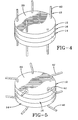
- FIG. 4 illustrates the sensor at a partially assembled state with plates 12, 14 positioned against opposite sides of connector block 16 and rod members 40 extending through the plates 12, 14. Thereafter, the terminal portions 42 of rods 40 are melted by the application of heated die (not shown) to extend along the top surface 20 of each plate at substantially a right angle. The angle of deformation of rod portions 42, while preferentially ninety degrees, may be varied if desired. Once cooled, the deformed portions 42 of rods 40 fixes the brass plates 12, 14 into their intended mutual position against the connector block 16 and avoids any horizontal or vertical slippage of the plates relative to the connector block that might otherwise occur. The avoidance of slippage is particularly important should the sensor be subsequently vulcanized into a tire rubber compound.
- One or more of the completed sensor assemblies as shown in FIG. 5 may be incorporated into a material monitor stress forces within the material.
- the composition of plates 12, 14 is selected so that metal wires (not shown) may be attached to the plate outer surfaces 20 by soldering or other known techniques.
- the device 10 may thus be connected to other mechanical devices or electronic circuitry (not shown) of conventional form.
- a signal may be induced into the sensor plates 12, 14.
- An antenna (not shown) may be positioned to pick up variations to the induced signal resulting from capacitance changes in the device.
- the air gap 48 Located within a rubber compound, the air gap 48 will vary in thickness as plates 12, 14 flex inward under the influence of stress forces.
- the capacitance of device 10 will accordingly change in proportion to the applied stress force.
- the change in capacitance may be monitored by associate circuits connected to device 10 and the level of stress within the material deduced from changes in capacitance levels.
- the subject invention satisfies the needs of the industry for a stress sensor that is readily and economically fabricated, assembled and deployed.
- the sensor 10 may be made in various shapes including the circular form shown in the preferred embodiment.
- the deformation of rods 40 is an economical means to attach the sensor components together and to maintain their preferred mutual orientation against vertical and horizontal slippage.
- the use of a heat deformable material in the construction of connector block 16 facilitates the bending of rod portions 42.
Landscapes
- Engineering & Computer Science (AREA)
- Power Engineering (AREA)
- Physics & Mathematics (AREA)
- General Physics & Mathematics (AREA)
- Measuring Fluid Pressure (AREA)
- Arrangements For Transmission Of Measured Signals (AREA)
- Tires In General (AREA)
- Force Measurement Appropriate To Specific Purposes (AREA)
Claims (8)
- Capteur (10) pour détecter des contraintes au sein d'une matière, comprenant une première et une deuxième plaque de condensateur (12, 14) maintenues à l'écart l'une de l'autre par un entrefer (48), un bloc de connexion (16) étant disposé entre les plaques de condensateur (12, 14) et maintenant ensemble les plaques de condensateur (12, 14) dans des orientations réciproques prédéterminées, le bloc de connexion (16) englobant plusieurs membres en forme de tige (40) faisant saillie par rapport aux côtés opposés du bloc de connexion (34, 36) et s'étendant jusque dans une plaque de condensateur respective (12, 14) pour fixer des portions périphériques (22) de chaque plaque de condensateur (12, 14) au bloc de connexion (16), caractérisé en ce que le capteur comprend en outre un membre faisant office d'élément d'espacement (18) et situé entre les plaques de condensateur (12, 14), le membre (18) faisant office d'élément d'espacement englobant des côtés opposés du membre faisant office d'élément d'espacement maintenus contre une surface respective (24) orientée vers l'intérieur des plaques de condensateur (12, 14) le long des portions périphériques de l'entrefer (48), l'entrefer (48) étant dimensionné de manière variable et étant étalonné le long des portions périphériques par rapport à l'épaisseur du membre faisant office d'élément d'espacement (18).
- Capteur selon la revendication 1, dans lequel les membres (40) en forme de tige du bloc de connexion s'étendant en direction axiale à travers les plaques de condensateur (12, 14) en direction du côté externe des plaques englobent des portions de tiges terminales (42) formant un angle par-dessus les plaques de condensateur (12, 14) le long du côté externe des plaques de condensateur.
- Capteur selon la revendication 2, dans lequel chaque portion de tige terminale respective (42) d'un membre (40) en forme de tige s'étend en formant un angle approximatif de 90° par rapport à l'axe longitudinal du membre (40) en forme de tige.
- Capteur selon l'une quelconque des revendications précédentes, dans lequel les membres en forme de tige (40) du bloc de connexion sont composés d'une matière plastique thermodéformable.
- Assemblage d'un bandage pneumatique et d'un capteur pour détecter des contraintes au sein d'une matière de caoutchouc pour bandage pneumatique, caractérisé par un bandage pneumatique possédant une zone cible composée au moins en partie de caoutchouc et un capteur (10) selon au moins une des revendications 1 à 4.
- Assemblage selon la revendication 5, dans lequel les membres (40) en forme de tige du bloc de connexion s'étendent en direction axiale à travers les plaques de condensateur (12, 14) jusqu'au côté externe des plaques et englobent des portions de tiges terminales (42) formées pour s'étendre par-dessus les plaques de condensateur (12, 14) le long du côté externe des plaques de condensateur, et dans lequel la portion de tige terminale (42) d'un membre en forme de tige (40) s'étend de préférence en formant un angle approximatif de 90° par rapport à l'axe longitudinal du membre (40) en forme de tige.
- Procédé d'assemblage d'un capteur (10) pour détecter des contraintes au sein d'une matière, le capteur (10) comprenant une première et une deuxième plaque de condensateur (12, 14), le procédé comprenant les étapes consistant à :a) former plusieurs trous de passage à travers des portions périphériques (22) de chaque plaque de condensateur (12, 14) ;b) disposer un bloc de connexion (16) entre les plaques de condensateur (12, 14) ;c) étendre plusieurs membres (40) en forme de tige à travers des trous de passage respectifs (30) dans les plaques de condensateur (12, 14) pour fixer les portions périphériques (22) de chaque plaque de condensateur (12, 14) au bloc de connexion (16) ; etd) former des portions de tiges terminales (42) des membres (40) en forme de tige par-dessus le côté externe d'une plaque de condensateur respective (12, 14) ;caractérisé en ce que
le bloc de connexion (16) disposé entre les plaques de condensateur (12, 14) englobe lesdits plusieurs membres (40) en forme de tige faisant saillie par rapport aux côtés opposés du bloc de connexion ; et
le procédé comprend en outre le fait d'écarter, l'une de l'autre, la première et la deuxième plaque de condensateur (12, 14) via un entrefer (48) de dimension variable en positionnant un membre (18) faisant office d'élément d'espacement entre les plaques de condensateur (12, 14), les côtés opposés du membre faisant office d'élément d'espacement venant se disposer contre une surface (24) orientée vers l'intérieur, des plaques de condensateur (12, 14) le long des portions périphériques de l'entrefer (48), et le fait d'étalonner l'entrefer (48) le long des portions périphériques par rapport à l'épaisseur du membre (18) faisant office d'élément d'espacement. - Procédé d'assemblage selon la revendication 7, comprenant en outre les étapes consistant à :réaliser le bloc de connexion (16) à partir d'une matière plastique thermodéformable ;étendre les portions terminales (42) des membres (40) faisant office de tige de raccordement sur une distance s'étendant au-delà du côté externe d'une plaque de condensateur respective (12, 14) etappliquer de la chaleur sur les portions terminales (42) des membres (40) faisant office de tige de raccordement, tout en déformant les portions terminales (42) par-dessus le côté externe de la plaque de condensateur respective (12, 14).
Applications Claiming Priority (2)
| Application Number | Priority Date | Filing Date | Title |
|---|---|---|---|
| US729600 | 2003-12-05 | ||
| US10/729,600 US6951139B2 (en) | 2003-12-05 | 2003-12-05 | Tire sensor and method of assembly |
Publications (2)
| Publication Number | Publication Date |
|---|---|
| EP1538433A1 EP1538433A1 (fr) | 2005-06-08 |
| EP1538433B1 true EP1538433B1 (fr) | 2007-10-24 |
Family
ID=34465798
Family Applications (1)
| Application Number | Title | Priority Date | Filing Date |
|---|---|---|---|
| EP04106127A Expired - Fee Related EP1538433B1 (fr) | 2003-12-05 | 2004-11-29 | Capteur capacitif pour pneumatique et méthode de montage |
Country Status (5)
| Country | Link |
|---|---|
| US (1) | US6951139B2 (fr) |
| EP (1) | EP1538433B1 (fr) |
| JP (1) | JP2005172818A (fr) |
| BR (1) | BRPI0405142A (fr) |
| DE (1) | DE602004009655T2 (fr) |
Families Citing this family (2)
| Publication number | Priority date | Publication date | Assignee | Title |
|---|---|---|---|---|
| US7284417B2 (en) * | 2005-07-28 | 2007-10-23 | Reynolds Charles W | Tire monitor |
| US11435176B2 (en) | 2019-03-26 | 2022-09-06 | The Boeing Company | Systems and methods for remote sensing of air gaps using a capacitor sensor array |
Family Cites Families (14)
| Publication number | Priority date | Publication date | Assignee | Title |
|---|---|---|---|---|
| US4168518A (en) * | 1977-05-10 | 1979-09-18 | Lee Shih Y | Capacitor transducer |
| US4458292A (en) * | 1982-07-22 | 1984-07-03 | Tward 2001 Limited | Multiple capacitor transducer |
| US4430690A (en) * | 1982-10-07 | 1984-02-07 | International Business Machines Corporation | Low inductance MLC capacitor with metal impregnation and solder bar contact |
| JPS61112807A (ja) * | 1984-11-07 | 1986-05-30 | 河西工業株式会社 | 自動車用内装部品の取付用クリツプ |
| JPS63141312U (fr) * | 1987-03-06 | 1988-09-19 | ||
| JPH01182028A (ja) * | 1988-01-18 | 1989-07-19 | Sakamoto Kogyo Kk | フランジを有する物品の固定方法および装置 |
| US5027076A (en) * | 1990-01-29 | 1991-06-25 | Ball Corporation | Open cage density sensor |
| US5075624A (en) * | 1990-05-29 | 1991-12-24 | North American Philips Corporation | Radio frequency quadrature coil construction for magnetic resonance imaging (mri) apparatus |
| US5610335A (en) * | 1993-05-26 | 1997-03-11 | Cornell Research Foundation | Microelectromechanical lateral accelerometer |
| US6026694A (en) * | 1998-03-30 | 2000-02-22 | Serena Industries Incorporated | Linear force sensing device |
| JP2000258261A (ja) * | 1999-03-10 | 2000-09-22 | Furukawa Electric Co Ltd:The | 静電容量型荷重センサ |
| JP2001241698A (ja) * | 2000-02-25 | 2001-09-07 | Sanyo Electric Co Ltd | 外装パネル及びこれを用いた冷凍装置 |
| JP2002039709A (ja) * | 2000-07-28 | 2002-02-06 | Mitsutoyo Corp | 静電容量式プローブデバイス及び変位測定回路 |
| EP1617197B8 (fr) * | 2001-07-10 | 2009-04-15 | Commissariat A L'energie Atomique | Dispositif de mesure de forces, notamment pour pneumatique |
-
2003
- 2003-12-05 US US10/729,600 patent/US6951139B2/en not_active Expired - Fee Related
-
2004
- 2004-11-24 JP JP2004338786A patent/JP2005172818A/ja active Pending
- 2004-11-26 BR BR0405142-4A patent/BRPI0405142A/pt not_active IP Right Cessation
- 2004-11-29 EP EP04106127A patent/EP1538433B1/fr not_active Expired - Fee Related
- 2004-11-29 DE DE602004009655T patent/DE602004009655T2/de not_active Expired - Lifetime
Non-Patent Citations (1)
| Title |
|---|
| None * |
Also Published As
| Publication number | Publication date |
|---|---|
| DE602004009655D1 (de) | 2007-12-06 |
| US20050120801A1 (en) | 2005-06-09 |
| BRPI0405142A (pt) | 2005-08-02 |
| EP1538433A1 (fr) | 2005-06-08 |
| US6951139B2 (en) | 2005-10-04 |
| DE602004009655T2 (de) | 2008-08-28 |
| JP2005172818A (ja) | 2005-06-30 |
Similar Documents
| Publication | Publication Date | Title |
|---|---|---|
| US5729128A (en) | Magnetic sensor with a magnetically sensitive component that is movable during calibration and rigidly attachable to a formed magnet | |
| EP1519173B1 (fr) | Capteur de force a semi-conducteur | |
| CN107449537B (zh) | 压力感测器的制造方法 | |
| CA1313060C (fr) | Transducteur de pression avec pont polymerique conducteur | |
| US6718827B1 (en) | Center-mount capacitive sensor with overload protection | |
| US6555767B1 (en) | Composite load cell | |
| KR101535451B1 (ko) | 센서 조립체 | |
| KR100972161B1 (ko) | 압력센서 | |
| US6311571B1 (en) | Seat belt tension sensor | |
| KR0184012B1 (ko) | 내연기관의 연소실내의 압력 탐지용 압력센서 | |
| EP1538433B1 (fr) | Capteur capacitif pour pneumatique et méthode de montage | |
| KR102012986B1 (ko) | 측정 플러그 및 측정 플러그를 조립하는 방법 | |
| KR20110071023A (ko) | 온도 센서, 온도 센서 제조 방법 및 대응하는 온도 센서 조립 방법 | |
| WO1991001681A1 (fr) | Transducteur a pont polymere conducteur | |
| US20020035878A1 (en) | Seat belt tension sensor | |
| US9446727B2 (en) | Flexible interior mount fascia bracket | |
| JPWO1998018168A1 (ja) | ホトインタラプタ | |
| US9709592B2 (en) | Wheel speed sensor | |
| US20090001850A1 (en) | Saw sensor with adjustable preload | |
| EP0149962A2 (fr) | Disque à déclic capteur de condition et méthode pour sa fabrication | |
| US20210190606A1 (en) | Strain gages and methods for manufacturing thereof | |
| US6437680B1 (en) | Process for manufacture of sensors, and sensor so made, particularly a temperature sensor | |
| EP0269759A1 (fr) | Jauge de contrainte en matière semi-conductrice | |
| KR102529671B1 (ko) | 센서 엘리먼트 | |
| JPH113804A (ja) | 低抵抗抵抗器及びその製造方法 |
Legal Events
| Date | Code | Title | Description |
|---|---|---|---|
| PUAI | Public reference made under article 153(3) epc to a published international application that has entered the european phase |
Free format text: ORIGINAL CODE: 0009012 |
|
| AK | Designated contracting states |
Kind code of ref document: A1 Designated state(s): AT BE BG CH CY CZ DE DK EE ES FI FR GB GR HU IE IS IT LI LU MC NL PL PT RO SE SI SK TR |
|
| AX | Request for extension of the european patent |
Extension state: AL HR LT LV MK YU |
|
| 17P | Request for examination filed |
Effective date: 20051208 |
|
| AKX | Designation fees paid |
Designated state(s): DE FR GB |
|
| GRAP | Despatch of communication of intention to grant a patent |
Free format text: ORIGINAL CODE: EPIDOSNIGR1 |
|
| GRAS | Grant fee paid |
Free format text: ORIGINAL CODE: EPIDOSNIGR3 |
|
| GRAA | (expected) grant |
Free format text: ORIGINAL CODE: 0009210 |
|
| AK | Designated contracting states |
Kind code of ref document: B1 Designated state(s): DE FR GB |
|
| REG | Reference to a national code |
Ref country code: GB Ref legal event code: FG4D |
|
| REF | Corresponds to: |
Ref document number: 602004009655 Country of ref document: DE Date of ref document: 20071206 Kind code of ref document: P |
|
| ET | Fr: translation filed | ||
| PLBE | No opposition filed within time limit |
Free format text: ORIGINAL CODE: 0009261 |
|
| STAA | Information on the status of an ep patent application or granted ep patent |
Free format text: STATUS: NO OPPOSITION FILED WITHIN TIME LIMIT |
|
| 26N | No opposition filed |
Effective date: 20080725 |
|
| PGFP | Annual fee paid to national office [announced via postgrant information from national office to epo] |
Ref country code: FR Payment date: 20081106 Year of fee payment: 5 |
|
| GBPC | Gb: european patent ceased through non-payment of renewal fee |
Effective date: 20081129 |
|
| PG25 | Lapsed in a contracting state [announced via postgrant information from national office to epo] |
Ref country code: GB Free format text: LAPSE BECAUSE OF NON-PAYMENT OF DUE FEES Effective date: 20081129 |
|
| PGFP | Annual fee paid to national office [announced via postgrant information from national office to epo] |
Ref country code: DE Payment date: 20101130 Year of fee payment: 7 |
|
| REG | Reference to a national code |
Ref country code: FR Ref legal event code: ST Effective date: 20110826 |
|
| PG25 | Lapsed in a contracting state [announced via postgrant information from national office to epo] |
Ref country code: FR Free format text: LAPSE BECAUSE OF NON-PAYMENT OF DUE FEES Effective date: 20091130 |
|
| REG | Reference to a national code |
Ref country code: DE Ref legal event code: R119 Ref document number: 602004009655 Country of ref document: DE Effective date: 20120601 |
|
| PG25 | Lapsed in a contracting state [announced via postgrant information from national office to epo] |
Ref country code: DE Free format text: LAPSE BECAUSE OF NON-PAYMENT OF DUE FEES Effective date: 20120601 |