EP1538308A1 - Compound valve assembly for controlling high and low oil flow and pressure - Google Patents
Compound valve assembly for controlling high and low oil flow and pressure Download PDFInfo
- Publication number
- EP1538308A1 EP1538308A1 EP04078214A EP04078214A EP1538308A1 EP 1538308 A1 EP1538308 A1 EP 1538308A1 EP 04078214 A EP04078214 A EP 04078214A EP 04078214 A EP04078214 A EP 04078214A EP 1538308 A1 EP1538308 A1 EP 1538308A1
- Authority
- EP
- European Patent Office
- Prior art keywords
- valve
- oil
- pressure
- chamber
- relief
- Prior art date
- Legal status (The legal status is an assumption and is not a legal conclusion. Google has not performed a legal analysis and makes no representation as to the accuracy of the status listed.)
- Withdrawn
Links
- 150000001875 compounds Chemical class 0.000 title claims abstract description 9
- 238000002485 combustion reaction Methods 0.000 claims description 6
- 238000004891 communication Methods 0.000 claims description 3
- 230000009849 deactivation Effects 0.000 claims description 3
- 239000003921 oil Substances 0.000 description 42
- 239000010705 motor oil Substances 0.000 description 5
- 238000010304 firing Methods 0.000 description 2
- 230000003071 parasitic effect Effects 0.000 description 2
- 230000004913 activation Effects 0.000 description 1
- 230000006835 compression Effects 0.000 description 1
- 238000007906 compression Methods 0.000 description 1
- 238000006073 displacement reaction Methods 0.000 description 1
- 239000000446 fuel Substances 0.000 description 1
- 230000006870 function Effects 0.000 description 1
- 230000013011 mating Effects 0.000 description 1
- 230000007246 mechanism Effects 0.000 description 1
- 238000000034 method Methods 0.000 description 1
- 230000000717 retained effect Effects 0.000 description 1
- 230000003319 supportive effect Effects 0.000 description 1
- 238000004804 winding Methods 0.000 description 1
Images

Classifications
-
- F—MECHANICAL ENGINEERING; LIGHTING; HEATING; WEAPONS; BLASTING
- F01—MACHINES OR ENGINES IN GENERAL; ENGINE PLANTS IN GENERAL; STEAM ENGINES
- F01L—CYCLICALLY OPERATING VALVES FOR MACHINES OR ENGINES
- F01L13/00—Modifications of valve-gear to facilitate reversing, braking, starting, changing compression ratio, or other specific operations
- F01L13/0005—Deactivating valves
-
- F—MECHANICAL ENGINEERING; LIGHTING; HEATING; WEAPONS; BLASTING
- F01—MACHINES OR ENGINES IN GENERAL; ENGINE PLANTS IN GENERAL; STEAM ENGINES
- F01L—CYCLICALLY OPERATING VALVES FOR MACHINES OR ENGINES
- F01L1/00—Valve-gear or valve arrangements, e.g. lift-valve gear
- F01L1/26—Valve-gear or valve arrangements, e.g. lift-valve gear characterised by the provision of two or more valves operated simultaneously by same transmitting-gear; peculiar to machines or engines with more than two lift-valves per cylinder
- F01L1/267—Valve-gear or valve arrangements, e.g. lift-valve gear characterised by the provision of two or more valves operated simultaneously by same transmitting-gear; peculiar to machines or engines with more than two lift-valves per cylinder with means for varying the timing or the lift of the valves
-
- F—MECHANICAL ENGINEERING; LIGHTING; HEATING; WEAPONS; BLASTING
- F01—MACHINES OR ENGINES IN GENERAL; ENGINE PLANTS IN GENERAL; STEAM ENGINES
- F01L—CYCLICALLY OPERATING VALVES FOR MACHINES OR ENGINES
- F01L1/00—Valve-gear or valve arrangements, e.g. lift-valve gear
- F01L1/34—Valve-gear or valve arrangements, e.g. lift-valve gear characterised by the provision of means for changing the timing of the valves without changing the duration of opening and without affecting the magnitude of the valve lift
- F01L1/344—Valve-gear or valve arrangements, e.g. lift-valve gear characterised by the provision of means for changing the timing of the valves without changing the duration of opening and without affecting the magnitude of the valve lift changing the angular relationship between crankshaft and camshaft, e.g. using helicoidal gear
-
- F—MECHANICAL ENGINEERING; LIGHTING; HEATING; WEAPONS; BLASTING
- F01—MACHINES OR ENGINES IN GENERAL; ENGINE PLANTS IN GENERAL; STEAM ENGINES
- F01L—CYCLICALLY OPERATING VALVES FOR MACHINES OR ENGINES
- F01L13/00—Modifications of valve-gear to facilitate reversing, braking, starting, changing compression ratio, or other specific operations
- F01L13/0015—Modifications of valve-gear to facilitate reversing, braking, starting, changing compression ratio, or other specific operations for optimising engine performances by modifying valve lift according to various working parameters, e.g. rotational speed, load, torque
-
- F—MECHANICAL ENGINEERING; LIGHTING; HEATING; WEAPONS; BLASTING
- F01—MACHINES OR ENGINES IN GENERAL; ENGINE PLANTS IN GENERAL; STEAM ENGINES
- F01L—CYCLICALLY OPERATING VALVES FOR MACHINES OR ENGINES
- F01L13/00—Modifications of valve-gear to facilitate reversing, braking, starting, changing compression ratio, or other specific operations
- F01L13/0015—Modifications of valve-gear to facilitate reversing, braking, starting, changing compression ratio, or other specific operations for optimising engine performances by modifying valve lift according to various working parameters, e.g. rotational speed, load, torque
- F01L13/0031—Modifications of valve-gear to facilitate reversing, braking, starting, changing compression ratio, or other specific operations for optimising engine performances by modifying valve lift according to various working parameters, e.g. rotational speed, load, torque by modification of tappet or pushrod length
-
- F—MECHANICAL ENGINEERING; LIGHTING; HEATING; WEAPONS; BLASTING
- F01—MACHINES OR ENGINES IN GENERAL; ENGINE PLANTS IN GENERAL; STEAM ENGINES
- F01L—CYCLICALLY OPERATING VALVES FOR MACHINES OR ENGINES
- F01L13/00—Modifications of valve-gear to facilitate reversing, braking, starting, changing compression ratio, or other specific operations
- F01L13/0015—Modifications of valve-gear to facilitate reversing, braking, starting, changing compression ratio, or other specific operations for optimising engine performances by modifying valve lift according to various working parameters, e.g. rotational speed, load, torque
- F01L13/0036—Modifications of valve-gear to facilitate reversing, braking, starting, changing compression ratio, or other specific operations for optimising engine performances by modifying valve lift according to various working parameters, e.g. rotational speed, load, torque the valves being driven by two or more cams with different shape, size or timing or a single cam profiled in axial and radial direction
-
- F—MECHANICAL ENGINEERING; LIGHTING; HEATING; WEAPONS; BLASTING
- F01—MACHINES OR ENGINES IN GENERAL; ENGINE PLANTS IN GENERAL; STEAM ENGINES
- F01L—CYCLICALLY OPERATING VALVES FOR MACHINES OR ENGINES
- F01L1/00—Valve-gear or valve arrangements, e.g. lift-valve gear
- F01L1/34—Valve-gear or valve arrangements, e.g. lift-valve gear characterised by the provision of means for changing the timing of the valves without changing the duration of opening and without affecting the magnitude of the valve lift
- F01L1/344—Valve-gear or valve arrangements, e.g. lift-valve gear characterised by the provision of means for changing the timing of the valves without changing the duration of opening and without affecting the magnitude of the valve lift changing the angular relationship between crankshaft and camshaft, e.g. using helicoidal gear
- F01L1/3442—Valve-gear or valve arrangements, e.g. lift-valve gear characterised by the provision of means for changing the timing of the valves without changing the duration of opening and without affecting the magnitude of the valve lift changing the angular relationship between crankshaft and camshaft, e.g. using helicoidal gear using hydraulic chambers with variable volume to transmit the rotating force
- F01L2001/34423—Details relating to the hydraulic feeding circuit
- F01L2001/34426—Oil control valves
-
- F—MECHANICAL ENGINEERING; LIGHTING; HEATING; WEAPONS; BLASTING
- F01—MACHINES OR ENGINES IN GENERAL; ENGINE PLANTS IN GENERAL; STEAM ENGINES
- F01L—CYCLICALLY OPERATING VALVES FOR MACHINES OR ENGINES
- F01L1/00—Valve-gear or valve arrangements, e.g. lift-valve gear
- F01L1/34—Valve-gear or valve arrangements, e.g. lift-valve gear characterised by the provision of means for changing the timing of the valves without changing the duration of opening and without affecting the magnitude of the valve lift
- F01L1/344—Valve-gear or valve arrangements, e.g. lift-valve gear characterised by the provision of means for changing the timing of the valves without changing the duration of opening and without affecting the magnitude of the valve lift changing the angular relationship between crankshaft and camshaft, e.g. using helicoidal gear
- F01L1/3442—Valve-gear or valve arrangements, e.g. lift-valve gear characterised by the provision of means for changing the timing of the valves without changing the duration of opening and without affecting the magnitude of the valve lift changing the angular relationship between crankshaft and camshaft, e.g. using helicoidal gear using hydraulic chambers with variable volume to transmit the rotating force
- F01L2001/34423—Details relating to the hydraulic feeding circuit
- F01L2001/34426—Oil control valves
- F01L2001/3443—Solenoid driven oil control valves
Definitions
- the present invention relates to internal combustion engines; more particularly, to valves for controlling the flow of oil to oil-activated engine components such as variable valve actuators and camshaft phasers; and most particularly, to a compound valve for controlling oil flow alternatively at a high pressure for element activation and at a low pressure for element deactivation.
- US Patent Application Publication No. US 2003/0200947 A1 discloses a hydraulic apparatus and return spring for latching and delatching a latching pin of a deactivating roller finger follower.
- the latching pin is disposed in, and extends from, a bore in an outer finger arm which is supported by a hydraulic lash adjuster.
- the pin engages a central slider member which follows the surface of a camshaft lobe.
- engine oil pressure supplied to the apparatus is increased to a level sufficient to overcome the force of the return spring and move the latching pin out of engagement with the slider member.
- the slider member continues to follow the surface of the camshaft, but the cam motion is not translated to the outer finger arm, and the valve is not actuated thereby.
- a special hydraulic valve lifter having radially-operative latching pins also may be actuated or deactuated hydraulically.
- a pushrod seat is disengaged to deactivate the associated engine valve, while the cam-follower portion continues to follow the cam lobe in lost motion.
- a compound valve assembly for controlling high and low oil flow and pressure in accordance with the invention includes a first valve and a second valve.
- the first valve serves as a pressure relief valve which, in the example shown, includes a spring-biased cup-shaped plunger disposed in a side gallery opening off a primary oil supply gallery leading to or from a device to be oil-actuated.
- the plunger is seated in a first valve seat, and the relief spring is sized such that the plunger is displaced conventionally from the first valve seat at a predetermined upper limit of oil pressure to allow some oil to flow past the plunger and to be returned to the oil sump.
- the side gallery is closable at its opposite end by a secondary valve seat and a solenoid-actuated/spring-returned valve head.
- a small passage through the plunger end leads to the second valve seat, whereby a chamber within the plunger is filled with oil.
- the solenoid When the solenoid is deactivated, oil also flows through the passage, through the second valve, and is returned to the sump.
- the solenoid When high oil flow and pressure are desired at the control device, the solenoid is energized, closing the second valve and capturing oil within the plunger.
- the captive oil assumes the same pressure as the supply pressure in the primary gallery, and the relief valve function is disabled.
- the flow and pressure of oil flowing through the primary gallery to the control device are both high.
- the solenoid is de-energized, reopening the second valve and again permitting oil pressure relief around and through the plunger.
- a compound valve assembly 10 in accordance with the invention comprises a first valve 11 including body 12, the body being generally cylindrical and adapted to be fitted into a first well 14 formed in an internal combustion engine 16.
- Well 14 intersects an oil supply gallery 18 wherein high pressure oil 20 is supplied as from an engine main oil pump (not shown).
- Well 14 further intersects a control gallery 22 leading to a device (not shown), such as for example, a deactivatable roller finger follower or hydraulic valve lifter, to be controlled by variable oil flow and pressure 24 as provided by assembly 10.
- First valve body 12 includes a first chamber 25 open to supply gallery 18 and control gallery 22.
- Valve body 12 may include a flow-restricting orifice 26 sized for the maximum flow rate desired. Orifice 26 reduces the parasitic flow from the pressure relief feature of the valve assembly and allows a higher pressure to be retained in parallel galleries from a common supply pump.
- First valve body 12 includes a second well 28 terminating in communication with first chamber 25 and defining an annular first valve seat 30 therebetween.
- a cup-shaped relief valve plunger 32 is disposed in second well 28 and is urged against first valve seat 30 by a compression spring 34 disposed within a second chamber 36 within relief valve plunger 32.
- a reduced-diameter portion 38 of first valve body 12 defines an annular space 40 between portion 38 and first well 14 of engine 16. Parasitic oil flow 42 being relieved by oil pressure displacement of relief valve plunger 32 from first valve seat 30 flows through radial port 44 into annular space 40.
- a second valve 45 includes a second valve body 46 having a first diameter portion 48 that is close-fitted into second well 28 in first valve body 12 and a second diameter portion 50 that is sealed as by an O-ring 52 against flange 54 of first body 12.
- Second valve body 46 includes a third well 56 concentric with first and second wells 14,28, terminating in a second valve seat 58 surrounding a passage 60 between second chamber 36 and third chamber 62 in second valve body 46.
- Second valve body 46 further defines a spring seat 35 (Fig. 2) for relief spring 34.
- An oil sump-return gallery 64 in engine 16 communicates with annular space 40 and also with passage 60 via radial port 66 in second valve body 46 and radial port 68 in first body 12.
- a solenoid actuator 70 having windings 71 is concentrically mounted onto second valve body 46 and includes a slidable armature 72 supportive of a secondary valve pintle 74 and valve head 76 for variably mating with second valve seat 58.
- a return spring 78 holds the secondary pintle valve 74 in the open position when the solenoid is de-energized.
- a passage 67 is provided through the end 69 of plunger 32, permitting oil from first chamber 25 to enter second chamber 36 within relief valve plunger 32 and to flow through the secondary valve when open and return to the engine sump via port 64.
- solenoid actuator 70 In operation in low-flow/low-pressure mode, as shown in FIG. 1, solenoid actuator 70 is de-energized. High pressure oil 20 at engine supply pressure flows through supply gallery 18, enters first chamber 25 via preferred restriction orifice 26 at a reduced flow and pressure, and exits first chamber 25 via control gallery 22.
- Relief spring 34 is sized to permit pressure relief of oil by displacing relief valve plunger 32 at a predetermined relatively low pressure level, oil flowing past plunger 32 and to sump return gallery 64 via annular space 40.
- excess oil flows through passage 67, filling second chamber 36 and flowing to sump return gallery 64 via passage 60 and second valve seat 58.
- the secondary pintle valve 74 is held open by spring 78.
- oil flow through control gallery 22 is never shut off, as it is in prior art spool valves, and always flows at some predetermined minimum flow rate and pressure.
- chamber 36 communicates with first chamber 25 via passage 67, and as pressure in first chamber 25 rises so does pressure in second chamber 36, balancing the hydraulic forces on plunger end 69; thus, relief spring 34 assists in keeping first valve 11 closed, allowing full engine oil pressure (minus whatever drop is dictated by orifice 26) to be applied to control gallery 22.
- the primary and secondary objects of the invention are realized: to controllably vary the flow of pressurized oil between a high-flow/high-pressure condition and a low flow/low-pressure condition, and to provide such control electromechanically via a simple solenoid valve.
Landscapes
- Engineering & Computer Science (AREA)
- Mechanical Engineering (AREA)
- General Engineering & Computer Science (AREA)
- Magnetically Actuated Valves (AREA)
- Valve Device For Special Equipments (AREA)
Abstract
Description
- The present invention relates to internal combustion engines; more particularly, to valves for controlling the flow of oil to oil-activated engine components such as variable valve actuators and camshaft phasers; and most particularly, to a compound valve for controlling oil flow alternatively at a high pressure for element activation and at a low pressure for element deactivation.
- It is known that for a portion of the duty cycle of a typical multiple-cylinder internal combustion engine, the load can be met by a functionally smaller engine having fewer firing cylinders, and that at low-demand times fuel efficiency can be improved if one or more cylinders of a larger engine can be withdrawn from firing service. It is known in the art to accomplish this by de-activating a portion of the valve train associated with pre-selected cylinders in any of various ways. For example, a special cam finger follower having a latching pin or slide which may be actuated and/or deactuated hydraulically. The cam finger follower is so configured that it causes low or no lift of the valve when the pin is disengaged and high lift of the valve when the pin is engaged.
- Various methods and apparatus for actuating this type of latching pin or slide are known. For example, US Patent Application Publication No. US 2003/0200947 A1 discloses a hydraulic apparatus and return spring for latching and delatching a latching pin of a deactivating roller finger follower. The latching pin is disposed in, and extends from, a bore in an outer finger arm which is supported by a hydraulic lash adjuster. When moved inwards of the outer finger arm, the pin engages a central slider member which follows the surface of a camshaft lobe. When valve deactivation is desired, engine oil pressure supplied to the apparatus is increased to a level sufficient to overcome the force of the return spring and move the latching pin out of engagement with the slider member. The slider member continues to follow the surface of the camshaft, but the cam motion is not translated to the outer finger arm, and the valve is not actuated thereby.
- For another example, a special hydraulic valve lifter having radially-operative latching pins also may be actuated or deactuated hydraulically. When the lifter is deactuated by high-pressure oil overcoming a latching spring, a pushrod seat is disengaged to deactivate the associated engine valve, while the cam-follower portion continues to follow the cam lobe in lost motion.
- In providing such actuation mechanisms, it can be advantageous to provide ordinary engine oil as the pressurized actuating medium, supplied conventionally from the main engine oil pump via a standard engine oil gallery with minimal special oil porting. Further, it is advantageous to be able to throttle the flow of oil between high-flow/high-pressure and low flow/low-pressure without ever completely shutting off the flow of oil, as is the case in prior art on/off solenoid-actuated spool valves.
- It is a principal object of the present invention to controllably vary the flow of pressurized oil between a high-flow/high-pressure condition and a low flow/low-pressure condition.
- It is a further object of the invention to provide such control electromechanically via a simple solenoid valve.
- Briefly described, a compound valve assembly for controlling high and low oil flow and pressure in accordance with the invention includes a first valve and a second valve. The first valve serves as a pressure relief valve which, in the example shown, includes a spring-biased cup-shaped plunger disposed in a side gallery opening off a primary oil supply gallery leading to or from a device to be oil-actuated. The plunger is seated in a first valve seat, and the relief spring is sized such that the plunger is displaced conventionally from the first valve seat at a predetermined upper limit of oil pressure to allow some oil to flow past the plunger and to be returned to the oil sump. The side gallery is closable at its opposite end by a secondary valve seat and a solenoid-actuated/spring-returned valve head. A small passage through the plunger end leads to the second valve seat, whereby a chamber within the plunger is filled with oil. When the solenoid is deactivated, oil also flows through the passage, through the second valve, and is returned to the sump. Thus, the flow and pressure of oil flowing through the primary oil gallery to the control device are both low because much of the supplied oil bypasses the control device. When high oil flow and pressure are desired at the control device, the solenoid is energized, closing the second valve and capturing oil within the plunger. Because of communication through the plunger passage, the captive oil assumes the same pressure as the supply pressure in the primary gallery, and the relief valve function is disabled. Thus the flow and pressure of oil flowing through the primary gallery to the control device are both high. To deactuate the valve assembly, the solenoid is de-energized, reopening the second valve and again permitting oil pressure relief around and through the plunger.
- The present invention will now be described, by way of example, with reference to the accompanying drawings, in which:
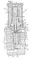
- FIG. 1 is a elevational cross-sectional view of a compound valve assembly in accordance with the invention disposed for use in an internal combustion engine, the valve assembly being shown in deactuation mode for providing low oil flow and pressure to a control device of the engine; and
- FIG.2 is a view like that shown in FIG. 1, but showing the valve assembly in actuation mode for providing high oil flow and pressure to the engine control device.
-
- Referring to FIG. 1, a
compound valve assembly 10 in accordance with the invention comprises afirst valve 11 includingbody 12, the body being generally cylindrical and adapted to be fitted into afirst well 14 formed in aninternal combustion engine 16. Well 14 intersects anoil supply gallery 18 whereinhigh pressure oil 20 is supplied as from an engine main oil pump (not shown). Well 14 further intersects acontrol gallery 22 leading to a device (not shown), such as for example, a deactivatable roller finger follower or hydraulic valve lifter, to be controlled by variable oil flow andpressure 24 as provided byassembly 10.First valve body 12 includes afirst chamber 25 open tosupply gallery 18 andcontrol gallery 22.Valve body 12 may include a flow-restrictingorifice 26 sized for the maximum flow rate desired. Orifice 26 reduces the parasitic flow from the pressure relief feature of the valve assembly and allows a higher pressure to be retained in parallel galleries from a common supply pump. -
First valve body 12 includes a second well 28 terminating in communication withfirst chamber 25 and defining an annularfirst valve seat 30 therebetween. A cup-shapedrelief valve plunger 32 is disposed insecond well 28 and is urged againstfirst valve seat 30 by acompression spring 34 disposed within asecond chamber 36 withinrelief valve plunger 32. A reduced-diameter portion 38 offirst valve body 12 defines anannular space 40 betweenportion 38 and first well 14 ofengine 16.Parasitic oil flow 42 being relieved by oil pressure displacement ofrelief valve plunger 32 fromfirst valve seat 30 flows throughradial port 44 intoannular space 40. - A
second valve 45 includes asecond valve body 46 having afirst diameter portion 48 that is close-fitted into second well 28 infirst valve body 12 and asecond diameter portion 50 that is sealed as by an O-ring 52 againstflange 54 offirst body 12.Second valve body 46 includes a third well 56 concentric with first andsecond wells second valve seat 58 surrounding apassage 60 betweensecond chamber 36 and third chamber 62 insecond valve body 46.Second valve body 46 further defines a spring seat 35 (Fig. 2) forrelief spring 34. An oil sump-return gallery 64 inengine 16 communicates withannular space 40 and also withpassage 60 viaradial port 66 insecond valve body 46 andradial port 68 infirst body 12. - A
solenoid actuator 70 havingwindings 71 is concentrically mounted ontosecond valve body 46 and includes aslidable armature 72 supportive of asecondary valve pintle 74 andvalve head 76 for variably mating withsecond valve seat 58. Areturn spring 78 holds thesecondary pintle valve 74 in the open position when the solenoid is de-energized. - A
passage 67 is provided through theend 69 ofplunger 32, permitting oil fromfirst chamber 25 to entersecond chamber 36 withinrelief valve plunger 32 and to flow through the secondary valve when open and return to the engine sump viaport 64. - In operation in low-flow/low-pressure mode, as shown in FIG. 1,
solenoid actuator 70 is de-energized.High pressure oil 20 at engine supply pressure flows throughsupply gallery 18, entersfirst chamber 25 viapreferred restriction orifice 26 at a reduced flow and pressure, and exitsfirst chamber 25 viacontrol gallery 22.Relief spring 34 is sized to permit pressure relief of oil by displacingrelief valve plunger 32 at a predetermined relatively low pressure level, oil flowing pastplunger 32 and to sumpreturn gallery 64 viaannular space 40. In addition, excess oil flows throughpassage 67, fillingsecond chamber 36 and flowing to sumpreturn gallery 64 viapassage 60 andsecond valve seat 58. Thesecondary pintle valve 74 is held open byspring 78. - It is an important aspect of the present invention that oil flow through
control gallery 22 is never shut off, as it is in prior art spool valves, and always flows at some predetermined minimum flow rate and pressure. - Referring to FIG. 2 (
engine 16 omitted for clarity), in order to increase oil flow and pressure incontrol gallery 22 when actuation of the control device is desired, the relief and excess oil flows shown in FIG. 1 must be shut off. This is accomplished by energizingsolenoid actuator 70 to closesecond valve 45 by engagingvalve head 76 withsecondary valve seat 58. Closing the secondary valve seat has two hydraulic consequences. First,second chamber 36 is completely filled with trapped oil, which is incompressible; thusrelief valve plunger 32 cannot be forced off offirst valve seat 30 as pressure begins to rise infirst chamber 25. Second,chamber 36 communicates withfirst chamber 25 viapassage 67, and as pressure infirst chamber 25 rises so does pressure insecond chamber 36, balancing the hydraulic forces onplunger end 69; thus,relief spring 34 assists in keepingfirst valve 11 closed, allowing full engine oil pressure (minus whatever drop is dictated by orifice 26) to be applied tocontrol gallery 22. - Thus the primary and secondary objects of the invention are realized: to controllably vary the flow of pressurized oil between a high-flow/high-pressure condition and a low flow/low-pressure condition, and to provide such control electromechanically via a simple solenoid valve.
- While the invention has been described by reference to various specific embodiments, it should be understood that numerous changes may be made within the spirit and scope of the inventive concepts described. Accordingly, it is intended that the invention not be limited to the described embodiments, but will have full scope defined by the language of the following claims.
Claims (7)
- A compound valve assembly (10) for controlling pressure drop in oil (20) flowing from a high pressure source (18) through said assembly into a control gallery (22), comprising:a) a primary valve (11) disposable in said flowing oil as a relief valve to bypass a portion (42) of said oil to provide low pressure in said oil flowing to said control gallery (22); andb) a controllable second valve (45) adjacent said primary valve (11) for allowing or preventing flow of said bypass oil to allow opening of said primary valve (11) as desired to provide said low oil pressure in said control gallery (22), and to prevent said opening of said primary valve (45) as desired to provide high oil pressure in said control gallery (22).
- A valve assembly (10) in accordance with Claim 1 wherein said primary valve (11 ) comprises:a) a first valve body (12) having first and second chambers (25,36) therein separated by a first valve seat (30);b) a relief plunger (32) disposed in said second chamber (36) for variably seating against said first valve seat (30);c) a relief spring (34) biasedly disposed in said second chamber (36) against said plunger (32) for preventing flow of oil (42) across said first valve seat (30) when oil pressure in said first chamber (25) is insufficient to overcome said relief spring bias; andd) a passage (67) through said relief plunger (32) for communication between said first and second chambers (25,36).
- A valve assembly (10) in accordance with Claim 2 wherein said second valve (45) comprises:a) a second valve body (46) disposed in said second chamber (36) and having a third chamber (56) separated from said second chamber (36) by a second valve seat (58);b) a pintle valve head (76) disposed in said third chamber (56) for variably seating against said second valve seat (58);c) a return spring (78) disposed against said pintle valve head (76) in said third chamber (56) for urging said second valve (45) toward an open position;d) means (70) for selectively closing said secondary valve; ande) a relief passage (64) leading from said third chamber for flow of oil passing through said secondary valve (45).
- A valve assembly (10) in accordance with Claim 3 wherein said means for closing includes a solenoid actuator (70) operatively connected to said pintle valve head (76).
- A valve assembly (10) in accordance with Claim 3 further including a flow path for said bypass oil (42) from said first chamber (25) to said relief passage (64), said flow path comprising:a) an annular space (40) around said first valve body (12) and communicating with said relief passage (64); andb) a port (66,68) connecting said second chamber (36) and said relief passage (64).
- A compound valve assembly (10) disposable in an internal combustion engine (16) for controlling pressure of oil (20) flowing from an oil pump through an oil supply gallery (18) into a control gallery (22) for variably controlling actuation of an engine component, comprising:a) a primary valve (11) disposable in said flowing oil (20) between said supply gallery (18) and said control gallery (22) to bypass a portion of said oil (20) to an oil sump (64) to provide low oil pressure in said control gallery (22); andb) a solenoid-actuable second valve (45) adjacent said primary valve (11) for allowing opening of said primary valve (11) to provide said low oil pressure (24) as desired in said control gallery (22), and for preventing said opening of said primary valve (11) to provide high oil pressure as desired in said control gallery (22).
- An internal combustion engine (16) having a system for deactivation of a least one engine valve, the engine comprising a compound valve assembly (10) for controlling pressure drop in oil (20) flowing from a high pressure source (18) through the valve assembly into a control gallery (22) for deactivating said valve, the valve assembly including,
a primary valve (11) disposable in said flowing oil (20) as a relief valve to bypass a portion of said oil (20) to provide low pressure (24) in said oil flowing to said control gallery (22), and
a controllable second valve (45) adjacent said primary valve (11 ) for allowing or preventing flow of said bypass oil to allow opening of said primary valve (11) as desired to provide said low oil pressure (24) in said control gallery (22), and to prevent said opening of said primary valve (11) as desired to provide high oil pressure (24) in said control gallery (22).
Applications Claiming Priority (2)
| Application Number | Priority Date | Filing Date | Title |
|---|---|---|---|
| US724664 | 2003-12-01 | ||
| US10/724,664 US6938873B2 (en) | 2003-12-01 | 2003-12-01 | Compound valve assembly for controlling high and low oil flow and pressure |
Publications (1)
| Publication Number | Publication Date |
|---|---|
| EP1538308A1 true EP1538308A1 (en) | 2005-06-08 |
Family
ID=34465727
Family Applications (1)
| Application Number | Title | Priority Date | Filing Date |
|---|---|---|---|
| EP04078214A Withdrawn EP1538308A1 (en) | 2003-12-01 | 2004-11-25 | Compound valve assembly for controlling high and low oil flow and pressure |
Country Status (2)
| Country | Link |
|---|---|
| US (1) | US6938873B2 (en) |
| EP (1) | EP1538308A1 (en) |
Cited By (2)
| Publication number | Priority date | Publication date | Assignee | Title |
|---|---|---|---|---|
| EP2388446A1 (en) * | 2010-05-07 | 2011-11-23 | Aisin Seiki Kabushiki Kaisha | Valvet timing control apparatus |
| CN105864471A (en) * | 2015-02-11 | 2016-08-17 | 胡斯可汽车控股有限公司 | Control valve with annular poppet check valve |
Families Citing this family (12)
| Publication number | Priority date | Publication date | Assignee | Title |
|---|---|---|---|---|
| CN101755155B (en) * | 2007-07-18 | 2013-02-27 | 卢克摩擦片和离合器两合公司 | Pressure relief valve for a hydraulic assembly |
| JP2011169215A (en) * | 2010-02-18 | 2011-09-01 | Hitachi Automotive Systems Ltd | Control valve apparatus |
| US8607823B2 (en) | 2010-07-13 | 2013-12-17 | Delphi Technologies, Inc. | Pressure control valve |
| JP5781800B2 (en) * | 2011-03-27 | 2015-09-24 | 株式会社山田製作所 | Relief valve device |
| US8651079B2 (en) | 2012-01-24 | 2014-02-18 | Honda Motor Co., Ltd. | Deactivating hydraulic valve lash adjuster/compensator with temporary lash compensation deactivation |
| US10508964B2 (en) | 2013-03-14 | 2019-12-17 | Eaton Intelligent Power Limited | Solenoid valve assembly with pilot pressure control |
| EP2877718B1 (en) * | 2013-03-14 | 2016-11-16 | Eaton Corporation | Engine valvetrain oil control valve |
| US9643310B2 (en) * | 2014-08-12 | 2017-05-09 | Caterpillar Inc. | Automatic lubrication system with detune |
| GB2539937B (en) | 2015-07-01 | 2019-07-24 | Ford Global Tech Llc | A combined oil filter and restrictor assembly |
| WO2018089614A1 (en) * | 2016-11-11 | 2018-05-17 | Eaton Corporation | Solenoid valve assembly with pilot pressure control |
| US10480712B2 (en) * | 2016-11-15 | 2019-11-19 | Caterpillar Inc. | System and method for preventing air in lubricant supply lines |
| US10989106B2 (en) * | 2016-12-02 | 2021-04-27 | Turbosmart Pty Limited | Oil pressure regulator |
Citations (6)
| Publication number | Priority date | Publication date | Assignee | Title |
|---|---|---|---|---|
| US4727830A (en) * | 1985-07-31 | 1988-03-01 | Honda Giken Kogyo Kabushiki Kaisha | Valve operating mechanism for internal combustion engine |
| EP0353988A1 (en) * | 1988-08-01 | 1990-02-07 | Honda Giken Kogyo Kabushiki Kaisha | Valve operating system for internal combustion engine |
| US5666915A (en) * | 1994-11-30 | 1997-09-16 | Honda Giken Kogyo Kabushiki Kaisha | Oil passage structure in an engine |
| WO1998008015A1 (en) * | 1996-08-23 | 1998-02-26 | Flow Safe, Inc. | Pilot operated safety relief valve |
| US5832891A (en) * | 1993-10-14 | 1998-11-10 | Audi A.G. | Valve gear mechanism for a multi-cylinder internal combustion engine |
| US20030200947A1 (en) * | 2002-04-12 | 2003-10-30 | Harris Wayne S. | Lock-pin cartridge for a two-step finger follower rocker arm |
Family Cites Families (5)
| Publication number | Priority date | Publication date | Assignee | Title |
|---|---|---|---|---|
| US3844528A (en) * | 1971-12-30 | 1974-10-29 | P Massie | Electrically operated hydraulic valve particularly adapted for pollution-free electronically controlled internal combustion engine |
| JPH0692743B2 (en) * | 1985-04-01 | 1994-11-16 | 日本電装株式会社 | Solenoid valve for fluid control |
| US4779837A (en) * | 1986-02-10 | 1988-10-25 | Tokyo Keiki Co., Ltd. | Remote control poppet valve |
| DE4446860A1 (en) * | 1994-12-27 | 1996-07-04 | Herion Werke Kg | Control valve used in power generation plants |
| US5887847A (en) * | 1997-09-18 | 1999-03-30 | Automatic Switch Company | Digitally controllable flow rate valve |
-
2003
- 2003-12-01 US US10/724,664 patent/US6938873B2/en not_active Expired - Lifetime
-
2004
- 2004-11-25 EP EP04078214A patent/EP1538308A1/en not_active Withdrawn
Patent Citations (6)
| Publication number | Priority date | Publication date | Assignee | Title |
|---|---|---|---|---|
| US4727830A (en) * | 1985-07-31 | 1988-03-01 | Honda Giken Kogyo Kabushiki Kaisha | Valve operating mechanism for internal combustion engine |
| EP0353988A1 (en) * | 1988-08-01 | 1990-02-07 | Honda Giken Kogyo Kabushiki Kaisha | Valve operating system for internal combustion engine |
| US5832891A (en) * | 1993-10-14 | 1998-11-10 | Audi A.G. | Valve gear mechanism for a multi-cylinder internal combustion engine |
| US5666915A (en) * | 1994-11-30 | 1997-09-16 | Honda Giken Kogyo Kabushiki Kaisha | Oil passage structure in an engine |
| WO1998008015A1 (en) * | 1996-08-23 | 1998-02-26 | Flow Safe, Inc. | Pilot operated safety relief valve |
| US20030200947A1 (en) * | 2002-04-12 | 2003-10-30 | Harris Wayne S. | Lock-pin cartridge for a two-step finger follower rocker arm |
Cited By (6)
| Publication number | Priority date | Publication date | Assignee | Title |
|---|---|---|---|---|
| EP2388446A1 (en) * | 2010-05-07 | 2011-11-23 | Aisin Seiki Kabushiki Kaisha | Valvet timing control apparatus |
| EP2664753A1 (en) * | 2010-05-07 | 2013-11-20 | Aisin Seiki Kabushiki Kaisha | Valve timing control apparatus |
| US8950370B2 (en) | 2010-05-07 | 2015-02-10 | Aisin Seiki Kabushiki Kaisha | Valve timing control apparatus |
| CN105864471A (en) * | 2015-02-11 | 2016-08-17 | 胡斯可汽车控股有限公司 | Control valve with annular poppet check valve |
| EP3056779A1 (en) * | 2015-02-11 | 2016-08-17 | HUSCO Automotive Holdings LLC | Control valve with annular poppet check valve |
| US9903280B2 (en) | 2015-02-11 | 2018-02-27 | Husco Automotive Holdings Llc | Control valve with annular poppet check valve |
Also Published As
| Publication number | Publication date |
|---|---|
| US20050116189A1 (en) | 2005-06-02 |
| US6938873B2 (en) | 2005-09-06 |
Similar Documents
| Publication | Publication Date | Title |
|---|---|---|
| US6904937B2 (en) | Switchable fluid control valve system | |
| US8720400B2 (en) | Three-port pintle valve for control of actuation oil | |
| US6938873B2 (en) | Compound valve assembly for controlling high and low oil flow and pressure | |
| JP4637727B2 (en) | Internal combustion engine with variable drive valve driven by a single pumping piston and controlled by a single solenoid valve for each engine cylinder | |
| US8607823B2 (en) | Pressure control valve | |
| US5626116A (en) | Dedicated rocker lever and cam assembly for a compression braking system | |
| US7263956B2 (en) | Valve lifter assembly for selectively deactivating a cylinder | |
| US5531192A (en) | Hydraulically actuated valve system | |
| EP1571300A2 (en) | Dual feed hydraulic lash adjuster | |
| EP0726390B1 (en) | Fuel system | |
| JP2009108862A (en) | Valve operating system for reciprocating internal combustion engine | |
| EP2443372A2 (en) | Fluid-biased hydraulic control valve | |
| JP4587889B2 (en) | Multi-cylinder engine | |
| US20110005481A1 (en) | Three-Port Pintle Valve for Control of Actuation Oil | |
| EP1464794A2 (en) | Engine valve actuator assembly with dual hydraulic feedback | |
| EP3137743B1 (en) | Valve timing system | |
| JP2000506951A (en) | Valve system that opens outward from the engine | |
| JP7250144B2 (en) | Engine valve mechanism parts that selectively reset lost motion | |
| US6003497A (en) | Mechanically actuated hydraulically amplified fuel injector with electrically controlled pressure relief | |
| US8353313B2 (en) | Three-port pintle valve for control of actuation oil | |
| JP4639130B2 (en) | INTERNAL COMBUSTION ENGINE HAVING HYDRAULIC OPERATING UNIT FOR CONTROLLING VALVE BY ROCKING OPERATION | |
| US8746279B2 (en) | Pressure control valve | |
| CN101451447B (en) | Valve operating system for variable displacement internal combustion engine | |
| US9416691B2 (en) | Internal-combustion engine having a system for variable actuation of the intake valves, provided with an electrically actuated valve having two ways and three positions | |
| JP5182125B2 (en) | Fuel supply pump |
Legal Events
| Date | Code | Title | Description |
|---|---|---|---|
| PUAI | Public reference made under article 153(3) epc to a published international application that has entered the european phase |
Free format text: ORIGINAL CODE: 0009012 |
|
| AK | Designated contracting states |
Kind code of ref document: A1 Designated state(s): AT BE BG CH CY CZ DE DK EE ES FI FR GB GR HU IE IS IT LI LU MC NL PL PT RO SE SI SK TR |
|
| AX | Request for extension of the european patent |
Extension state: AL HR LT LV MK YU |
|
| 17P | Request for examination filed |
Effective date: 20051208 |
|
| AKX | Designation fees paid |
Designated state(s): AT BE BG CH CY CZ DE DK EE ES FI FR GB GR HU IE IS IT LI LU MC NL PL PT RO SE SI SK TR |
|
| 17Q | First examination report despatched |
Effective date: 20060113 |
|
| GRAP | Despatch of communication of intention to grant a patent |
Free format text: ORIGINAL CODE: EPIDOSNIGR1 |
|
| STAA | Information on the status of an ep patent application or granted ep patent |
Free format text: STATUS: THE APPLICATION IS DEEMED TO BE WITHDRAWN |
|
| 18D | Application deemed to be withdrawn |
Effective date: 20080429 |