EP1538305A2 - Airfoil with variable density array of pedestals at the trailing edge - Google Patents
Airfoil with variable density array of pedestals at the trailing edge Download PDFInfo
- Publication number
- EP1538305A2 EP1538305A2 EP04255681A EP04255681A EP1538305A2 EP 1538305 A2 EP1538305 A2 EP 1538305A2 EP 04255681 A EP04255681 A EP 04255681A EP 04255681 A EP04255681 A EP 04255681A EP 1538305 A2 EP1538305 A2 EP 1538305A2
- Authority
- EP
- European Patent Office
- Prior art keywords
- rows
- turbine engine
- trailing edge
- pedestals
- cooling
- Prior art date
- Legal status (The legal status is an assumption and is not a legal conclusion. Google has not performed a legal analysis and makes no representation as to the accuracy of the status listed.)
- Granted
Links
Images


Classifications
-
- F—MECHANICAL ENGINEERING; LIGHTING; HEATING; WEAPONS; BLASTING
- F01—MACHINES OR ENGINES IN GENERAL; ENGINE PLANTS IN GENERAL; STEAM ENGINES
- F01D—NON-POSITIVE DISPLACEMENT MACHINES OR ENGINES, e.g. STEAM TURBINES
- F01D5/00—Blades; Blade-carrying members; Heating, heat-insulating, cooling or antivibration means on the blades or the members
- F01D5/12—Blades
- F01D5/14—Form or construction
- F01D5/18—Hollow blades, i.e. blades with cooling or heating channels or cavities; Heating, heat-insulating or cooling means on blades
-
- F—MECHANICAL ENGINEERING; LIGHTING; HEATING; WEAPONS; BLASTING
- F01—MACHINES OR ENGINES IN GENERAL; ENGINE PLANTS IN GENERAL; STEAM ENGINES
- F01D—NON-POSITIVE DISPLACEMENT MACHINES OR ENGINES, e.g. STEAM TURBINES
- F01D5/00—Blades; Blade-carrying members; Heating, heat-insulating, cooling or antivibration means on the blades or the members
- F01D5/12—Blades
- F01D5/14—Form or construction
- F01D5/18—Hollow blades, i.e. blades with cooling or heating channels or cavities; Heating, heat-insulating or cooling means on blades
- F01D5/187—Convection cooling
-
- F—MECHANICAL ENGINEERING; LIGHTING; HEATING; WEAPONS; BLASTING
- F05—INDEXING SCHEMES RELATING TO ENGINES OR PUMPS IN VARIOUS SUBCLASSES OF CLASSES F01-F04
- F05D—INDEXING SCHEME FOR ASPECTS RELATING TO NON-POSITIVE-DISPLACEMENT MACHINES OR ENGINES, GAS-TURBINES OR JET-PROPULSION PLANTS
- F05D2260/00—Function
- F05D2260/20—Heat transfer, e.g. cooling
- F05D2260/221—Improvement of heat transfer
- F05D2260/2212—Improvement of heat transfer by creating turbulence
Definitions
- the present invention relates to a component for use in a turbine engine, such as a vane or blade, having improved trailing edge cooling.
- Turbine engine components such as vanes and blades are subject to temperature extremes. Thus, it becomes necessary to cool various portions of the components.
- the trailing edge portions of such components are provided with cooling passages and a series of outlets along the trailing edge communication with the passages.
- a turbine engine component has means for cooling a trailing edge portion, which means comprises a plurality of rows of pedestals which vary in density along a span of the component.
- the number of rows of pedestals increases as one moves along the span of the component from an inner diameter region to an outer diameter region.
- Incorporation of a spanwisely variable density pedestal array in a turbine engine component enables the optimization of internal cooling fluid, typically air, heat up by balancing the heat up and pressure loss of the cooling fluid in both the radial and axial directions.
- internal cooling fluid typically air
- the ability to optimize the internal convective efficiency which is a measure of the potential a fluid has to extract heat from a known heat source, is critical in establishing the oxidation capability of a component for the minimum given available flow rate allotted.
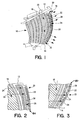
- a turbine engine component 10 such as an airfoil portion of a vane or blade
- the component 10 has an OD edge 12 and an inner diameter (ID) edge 14.
- ID inner diameter
- the cooling passageway 18 has an inlet 20 at the OD edge 12 of the component 10.
- the cooling fluid in the cooling passageway 18 is exhausted at the trailing edge 16 of the component 10 through a plurality of trailing edge slots 22.
- Each pedestal row 24 comprises a plurality of pedestals 26 of any desired shape or configuration. Adjacent ones of the pedestals 26 form a cooling channel 28 which receives cooling fluid from the cooling passageway 18 and which distributes the cooling fluid for exhaust through one or more of the slots 22.
- the density of the pedestal rows 24 varies along the span of the turbine engine component 10. As can be seen from FIG. 1, the number of pedestal rows 24 increases as one moves along the span of the component 10 from the ID edge 14 to the OD edge 12. In particular, the density of the pedestal rows 24 is greater in the OD region 30 of the component 10 than the ID region 32. In a preferred embodiment, there are at least twice as many pedestal rows 24 in the OD region 30 than in the ID region 32. In a most preferred embodiment, there are seven pedestal rows 24 in the OD region 30 and three pedestal rows 24 in the ID region 32.
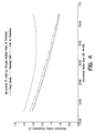
- the increased pressure loss associated with the higher axial pedestal row density at the OD region 30 of the component 10 minimizes the total coolant flow exhausted into the main stream through trailing edge slot tear drop region 40. Due to the increased number of pedestal rows 24 in the OD region 30, the convective efficiency is optimized as the cooler coolant fluid, typically coolant air, is heated significantly more as it migrates axially through the increased density pedestal array of the present invention. This is reflected by the graph shown in FIG. 4. Since the coolant mass flow at the OD edge 12 incurs more heat extraction, a higher net heat flux results for a constant radial coolant mass flow rate.
- the reduced pressure loss associated with the lower axial pedestal row density in the ID portion 32 of the component 10 is beneficial from two perspectives.
- the absolute driving pressure level at the ID portion 32 of the component 10 is reduced, minimizing the axial pressure loss through the lower density ID pedestal array. This enables the optimum local trailing edge slot coolant flow rate to be achieved. This is reflected by the graph shown in FIG. 5.
- the lower density of axial pedestals also reduces the total coolant air heat up as it migrates axially through the reduced density pedestal array and is reflected by the graph of FIG. 4.
- the coolant flow as it progresses along a radial path from the OD region 30 to the ID region 32 of the component trailing edge passage is able to be mitigated as flow migrates in the axial direction through the reduced density pedestal array at the ID region 32 of the component 10.
- a spanwise variable density pedestal array in accordance with the present invention ensures slot flow rate uniformity of the exhaustive coolant, as shown in the graph of FIG. 6, by offsetting frictional loss and temperature rise incurred by the working fluid.
Landscapes
- Engineering & Computer Science (AREA)
- Mechanical Engineering (AREA)
- General Engineering & Computer Science (AREA)
- Turbine Rotor Nozzle Sealing (AREA)
Abstract
Description
Claims (12)
- A turbine engine component (10) having a trailing edge portion (16), said component comprising:means for cooling the trailing edge portion (16); andsaid cooling means comprising a plurality of rows (24) of pedestals (26) which varies into density along a span of the component.
- A turbine engine component according to claim 1, wherein the number of rows (24) of pedestals (26) increases as one moves along the span of the component (10) from an inner diameter region (32) to an outer diameter region (30).
- A turbine engine component according to claim 1, wherein the number of rows (24) of pedestals (26) in an outer diameter region (30) of said component (10) is greater than the number of rows (24) of pedestals (26) in an inner diameter region (32) of said component.
- A turbine engine component according to claim 2 or 3, wherein the number of pedestal rows (24) in the outer diameter region (30) is at least twice as many as the number of pedestal rows (24) in the inner diameter region (32).
- A turbine engine component according to claim 2 or 3, wherein there are seven pedestal rows (24) in the outer diameter region (30) and three pedestal rows (24) in the inner diameter region (3 2).
- A turbine engine component according to any preceding claim, wherein said cooling means further comprises a cooling passage (18) having an inlet (20) at the outer diameter (OD) of the component (10), which cooling passage provides a cooling fluid to said pedestal rows (24), and a plurality of slots (22) along a trailing edge (16) of said component through which said cooling fluid is exhausted, which slots (22) are in fluid communication with a region containing said pedestal rows (24).
- A turbine engine component according to claim 6, wherein said variable density pedestal rows (24) optimizes trailing edge slot coolant Mach number and velocity with coolant air temperature rise and local thermal convective efficiency and performance.
- A turbine engine component according to any preceding claim, wherein said component (10) comprises a vane and said cooling means is located in an airfoil portion of said vane.
- A turbine engine component according to any of claims 1 to 7, wherein said component (10) comprises a blade and said cooling means is located in an airfoil portion of said blade.
- A turbine engine component (10) comprising:an airfoil portion having an outer edge portion (30) and an inner edge portion (32);a cooling passageway (18) located in said airfoil portion for providing cooling fluid to a trailing edge portion of said airfoil portion;a plurality of cooling slots (32) in said trailing edge portion for exhausting said cooling fluid; andmeans for uniformly optimizing trailing edge slot coolant Mach number and velocity with coolant air temperature rise and local thermal convective efficiency and performance.
- A turbine engine component according to claim 10, wherein said uniformly optimizing means comprises a plurality of rows (24) of pedestals (26) having a spanwise variable density.
- A turbine engine component according to claim 11, wherein the number of rows (24) of said pedestals (26) adjacent said inner edge portion (32) is less than the number of rows (24) of said pedestals (26) adjacent said outer edge portion (30) .
Applications Claiming Priority (2)
| Application Number | Priority Date | Filing Date | Title |
|---|---|---|---|
| US717806 | 2003-11-19 | ||
| US10/717,806 US6939107B2 (en) | 2003-11-19 | 2003-11-19 | Spanwisely variable density pedestal array |
Publications (3)
| Publication Number | Publication Date |
|---|---|
| EP1538305A2 true EP1538305A2 (en) | 2005-06-08 |
| EP1538305A3 EP1538305A3 (en) | 2006-07-26 |
| EP1538305B1 EP1538305B1 (en) | 2010-04-28 |
Family
ID=34465650
Family Applications (1)
| Application Number | Title | Priority Date | Filing Date |
|---|---|---|---|
| EP04255681A Expired - Lifetime EP1538305B1 (en) | 2003-11-19 | 2004-09-17 | Airfoil with variable density array of pedestals at the trailing edge |
Country Status (9)
| Country | Link |
|---|---|
| US (1) | US6939107B2 (en) |
| EP (1) | EP1538305B1 (en) |
| JP (1) | JP4057573B2 (en) |
| KR (1) | KR20050048461A (en) |
| CN (1) | CN1619108A (en) |
| CA (1) | CA2481351A1 (en) |
| DE (1) | DE602004026814D1 (en) |
| IL (1) | IL164053A0 (en) |
| SG (1) | SG112010A1 (en) |
Cited By (3)
| Publication number | Priority date | Publication date | Assignee | Title |
|---|---|---|---|---|
| EP1553261A2 (en) | 2004-01-09 | 2005-07-13 | United Technologies Corporation | Fanned trailing edge teardrop array |
| JP2007292006A (en) * | 2006-04-27 | 2007-11-08 | Hitachi Ltd | Turbine blade having a cooling passage inside |
| EP2925970A4 (en) * | 2012-11-28 | 2015-12-30 | United Technologies Corp | Trailing edge and tip cooling |
Families Citing this family (9)
| Publication number | Priority date | Publication date | Assignee | Title |
|---|---|---|---|---|
| US20080031739A1 (en) * | 2006-08-01 | 2008-02-07 | United Technologies Corporation | Airfoil with customized convective cooling |
| US20090003987A1 (en) * | 2006-12-21 | 2009-01-01 | Jack Raul Zausner | Airfoil with improved cooling slot arrangement |
| US8087893B1 (en) * | 2009-04-03 | 2012-01-03 | Florida Turbine Technologies, Inc. | Turbine blade with showerhead film cooling holes |
| US8353669B2 (en) * | 2009-08-18 | 2013-01-15 | United Technologies Corporation | Turbine vane platform leading edge cooling holes |
| US9328617B2 (en) * | 2012-03-20 | 2016-05-03 | United Technologies Corporation | Trailing edge or tip flag antiflow separation |
| EP2682565B8 (en) * | 2012-07-02 | 2016-09-21 | General Electric Technology GmbH | Cooled blade for a gas turbine |
| WO2017095438A1 (en) | 2015-12-04 | 2017-06-08 | Siemens Aktiengesellschaft | Turbine airfoil with biased trailing edge cooling arrangement |
| CN105569740A (en) * | 2016-03-03 | 2016-05-11 | 哈尔滨工程大学 | Turbine with blade wavy concave tailing edge slot cooling structures |
| US11939883B2 (en) | 2018-11-09 | 2024-03-26 | Rtx Corporation | Airfoil with arced pedestal row |
Family Cites Families (7)
| Publication number | Priority date | Publication date | Assignee | Title |
|---|---|---|---|---|
| GB895077A (en) * | 1959-12-09 | 1962-05-02 | Rolls Royce | Blades for fluid flow machines such as axial flow turbines |
| US4278400A (en) * | 1978-09-05 | 1981-07-14 | United Technologies Corporation | Coolable rotor blade |
| US4775296A (en) * | 1981-12-28 | 1988-10-04 | United Technologies Corporation | Coolable airfoil for a rotary machine |
| JPS62228603A (en) * | 1986-03-31 | 1987-10-07 | Toshiba Corp | Gas turbine blade |
| JP3040656B2 (en) * | 1994-05-12 | 2000-05-15 | 三菱重工業株式会社 | Gas Turbine Blade Platform Cooling System |
| US6257831B1 (en) * | 1999-10-22 | 2001-07-10 | Pratt & Whitney Canada Corp. | Cast airfoil structure with openings which do not require plugging |
| US6270317B1 (en) * | 1999-12-18 | 2001-08-07 | General Electric Company | Turbine nozzle with sloped film cooling |
-
2003
- 2003-11-19 US US10/717,806 patent/US6939107B2/en not_active Expired - Lifetime
-
2004
- 2004-09-13 CA CA002481351A patent/CA2481351A1/en not_active Abandoned
- 2004-09-13 IL IL16405304A patent/IL164053A0/en unknown
- 2004-09-16 KR KR1020040074026A patent/KR20050048461A/en not_active Abandoned
- 2004-09-17 SG SG200405114A patent/SG112010A1/en unknown
- 2004-09-17 CN CNA2004100855256A patent/CN1619108A/en active Pending
- 2004-09-17 DE DE602004026814T patent/DE602004026814D1/en not_active Expired - Lifetime
- 2004-09-17 EP EP04255681A patent/EP1538305B1/en not_active Expired - Lifetime
- 2004-09-21 JP JP2004272694A patent/JP4057573B2/en not_active Expired - Fee Related
Cited By (6)
| Publication number | Priority date | Publication date | Assignee | Title |
|---|---|---|---|---|
| EP1553261A2 (en) | 2004-01-09 | 2005-07-13 | United Technologies Corporation | Fanned trailing edge teardrop array |
| EP1553261A3 (en) * | 2004-01-09 | 2008-11-19 | United Technologies Corporation | Fanned trailing edge teardrop array |
| JP2007292006A (en) * | 2006-04-27 | 2007-11-08 | Hitachi Ltd | Turbine blade having a cooling passage inside |
| EP1849960A3 (en) * | 2006-04-27 | 2010-03-10 | Hitachi, Ltd. | Turbine blade having internal cooling passage |
| EP2925970A4 (en) * | 2012-11-28 | 2015-12-30 | United Technologies Corp | Trailing edge and tip cooling |
| US9482101B2 (en) | 2012-11-28 | 2016-11-01 | United Technologies Corporation | Trailing edge and tip cooling |
Also Published As
| Publication number | Publication date |
|---|---|
| KR20050048461A (en) | 2005-05-24 |
| JP4057573B2 (en) | 2008-03-05 |
| JP2005147131A (en) | 2005-06-09 |
| US6939107B2 (en) | 2005-09-06 |
| IL164053A0 (en) | 2005-12-18 |
| CN1619108A (en) | 2005-05-25 |
| EP1538305B1 (en) | 2010-04-28 |
| CA2481351A1 (en) | 2005-05-19 |
| EP1538305A3 (en) | 2006-07-26 |
| SG112010A1 (en) | 2005-06-29 |
| US20050106007A1 (en) | 2005-05-19 |
| DE602004026814D1 (en) | 2010-06-10 |
Similar Documents
| Publication | Publication Date | Title |
|---|---|---|
| US10876413B2 (en) | Turbine airfoils with micro cooling features | |
| US8894352B2 (en) | Ring segment with forked cooling passages | |
| US7527475B1 (en) | Turbine blade with a near-wall cooling circuit | |
| EP1630354B1 (en) | Cooled gas turbine aerofoil | |
| EP1467064B1 (en) | Cooled Hollow airfoil | |
| US7575414B2 (en) | Turbine nozzle with trailing edge convection and film cooling | |
| EP1106781B1 (en) | Coolable vane or blade for a turbomachine | |
| JP4659206B2 (en) | Turbine nozzle with graded film cooling | |
| US8177507B2 (en) | Triangular serpentine cooling channels | |
| US8052390B1 (en) | Turbine airfoil with showerhead cooling | |
| EP1749972A2 (en) | Turbine component comprising a multiplicity of cooling passages | |
| US7967568B2 (en) | Gas turbine component with reduced cooling air requirement | |
| EP3124746A1 (en) | Method for cooling a turbo-engine component and turbo-engine component | |
| EP1538305B1 (en) | Airfoil with variable density array of pedestals at the trailing edge | |
| US20130084191A1 (en) | Turbine blade with impingement cavity cooling including pin fins | |
| RU2531839C2 (en) | Gas turbine | |
| US8079811B1 (en) | Turbine blade with multi-impingement cooled squealer tip | |
| EP1992784B1 (en) | Cooling arrangement | |
| CN108999645B (en) | Blade for gas turbine and power generation device comprising said blade | |
| JPS58119902A (en) | Forced cooling type fluid directional blade-shaped member for combustion turbine | |
| CN107762563A (en) | With polycolporate engine component |
Legal Events
| Date | Code | Title | Description |
|---|---|---|---|
| PUAI | Public reference made under article 153(3) epc to a published international application that has entered the european phase |
Free format text: ORIGINAL CODE: 0009012 |
|
| AK | Designated contracting states |
Kind code of ref document: A2 Designated state(s): AT BE BG CH CY CZ DE DK EE ES FI FR GB GR HU IE IT LI LU MC NL PL PT RO SE SI SK TR |
|
| AX | Request for extension of the european patent |
Extension state: AL HR LT LV MK |
|
| PUAL | Search report despatched |
Free format text: ORIGINAL CODE: 0009013 |
|
| AK | Designated contracting states |
Kind code of ref document: A3 Designated state(s): AT BE BG CH CY CZ DE DK EE ES FI FR GB GR HU IE IT LI LU MC NL PL PT RO SE SI SK TR |
|
| AX | Request for extension of the european patent |
Extension state: AL HR LT LV MK |
|
| 17P | Request for examination filed |
Effective date: 20061106 |
|
| AKX | Designation fees paid |
Designated state(s): DE FR GB IT |
|
| 17Q | First examination report despatched |
Effective date: 20070322 |
|
| GRAP | Despatch of communication of intention to grant a patent |
Free format text: ORIGINAL CODE: EPIDOSNIGR1 |
|
| GRAS | Grant fee paid |
Free format text: ORIGINAL CODE: EPIDOSNIGR3 |
|
| GRAA | (expected) grant |
Free format text: ORIGINAL CODE: 0009210 |
|
| AK | Designated contracting states |
Kind code of ref document: B1 Designated state(s): DE FR GB IT |
|
| REG | Reference to a national code |
Ref country code: GB Ref legal event code: FG4D |
|
| REF | Corresponds to: |
Ref document number: 602004026814 Country of ref document: DE Date of ref document: 20100610 Kind code of ref document: P |
|
| PLBE | No opposition filed within time limit |
Free format text: ORIGINAL CODE: 0009261 |
|
| STAA | Information on the status of an ep patent application or granted ep patent |
Free format text: STATUS: NO OPPOSITION FILED WITHIN TIME LIMIT |
|
| PG25 | Lapsed in a contracting state [announced via postgrant information from national office to epo] |
Ref country code: IT Free format text: LAPSE BECAUSE OF FAILURE TO SUBMIT A TRANSLATION OF THE DESCRIPTION OR TO PAY THE FEE WITHIN THE PRESCRIBED TIME-LIMIT Effective date: 20100428 |
|
| 26N | No opposition filed |
Effective date: 20110131 |
|
| REG | Reference to a national code |
Ref country code: FR Ref legal event code: ST Effective date: 20110531 |
|
| PG25 | Lapsed in a contracting state [announced via postgrant information from national office to epo] |
Ref country code: FR Free format text: LAPSE BECAUSE OF NON-PAYMENT OF DUE FEES Effective date: 20100930 |
|
| REG | Reference to a national code |
Ref country code: DE Ref legal event code: R082 Ref document number: 602004026814 Country of ref document: DE Representative=s name: SCHMITT-NILSON SCHRAUD WAIBEL WOHLFROM PATENTA, DE |
|
| REG | Reference to a national code |
Ref country code: DE Ref legal event code: R082 Ref document number: 602004026814 Country of ref document: DE Representative=s name: SCHMITT-NILSON SCHRAUD WAIBEL WOHLFROM PATENTA, DE Ref country code: DE Ref legal event code: R081 Ref document number: 602004026814 Country of ref document: DE Owner name: UNITED TECHNOLOGIES CORP. (N.D.GES.D. STAATES , US Free format text: FORMER OWNER: UNITED TECHNOLOGIES CORP., HARTFORD, CONN., US |
|
| PGFP | Annual fee paid to national office [announced via postgrant information from national office to epo] |
Ref country code: DE Payment date: 20190820 Year of fee payment: 16 |
|
| PGFP | Annual fee paid to national office [announced via postgrant information from national office to epo] |
Ref country code: GB Payment date: 20190820 Year of fee payment: 16 |
|
| REG | Reference to a national code |
Ref country code: DE Ref legal event code: R119 Ref document number: 602004026814 Country of ref document: DE |
|
| GBPC | Gb: european patent ceased through non-payment of renewal fee |
Effective date: 20200917 |
|
| PG25 | Lapsed in a contracting state [announced via postgrant information from national office to epo] |
Ref country code: DE Free format text: LAPSE BECAUSE OF NON-PAYMENT OF DUE FEES Effective date: 20210401 |
|
| PG25 | Lapsed in a contracting state [announced via postgrant information from national office to epo] |
Ref country code: GB Free format text: LAPSE BECAUSE OF NON-PAYMENT OF DUE FEES Effective date: 20200917 |