EP1538068A2 - Collision avoidance control for vehicles - Google Patents
Collision avoidance control for vehicles Download PDFInfo
- Publication number
- EP1538068A2 EP1538068A2 EP04028471A EP04028471A EP1538068A2 EP 1538068 A2 EP1538068 A2 EP 1538068A2 EP 04028471 A EP04028471 A EP 04028471A EP 04028471 A EP04028471 A EP 04028471A EP 1538068 A2 EP1538068 A2 EP 1538068A2
- Authority
- EP
- European Patent Office
- Prior art keywords
- vehicle
- obstacle
- traveling
- avoidance
- target
- Prior art date
- Legal status (The legal status is an assumption and is not a legal conclusion. Google has not performed a legal analysis and makes no representation as to the accuracy of the status listed.)
- Granted
Links
Images


Classifications
-
- B—PERFORMING OPERATIONS; TRANSPORTING
- B62—LAND VEHICLES FOR TRAVELLING OTHERWISE THAN ON RAILS
- B62D—MOTOR VEHICLES; TRAILERS
- B62D15/00—Steering not otherwise provided for
- B62D15/02—Steering position indicators ; Steering position determination; Steering aids
- B62D15/025—Active steering aids, e.g. helping the driver by actively influencing the steering system after environment evaluation
- B62D15/0265—Automatic obstacle avoidance by steering
-
- B—PERFORMING OPERATIONS; TRANSPORTING
- B62—LAND VEHICLES FOR TRAVELLING OTHERWISE THAN ON RAILS
- B62D—MOTOR VEHICLES; TRAILERS
- B62D6/00—Arrangements for automatically controlling steering depending on driving conditions sensed and responded to, e.g. control circuits
- B62D6/002—Arrangements for automatically controlling steering depending on driving conditions sensed and responded to, e.g. control circuits computing target steering angles for front or rear wheels
-
- B—PERFORMING OPERATIONS; TRANSPORTING
- B60—VEHICLES IN GENERAL
- B60G—VEHICLE SUSPENSION ARRANGEMENTS
- B60G2400/00—Indexing codes relating to detected, measured or calculated conditions or factors
- B60G2400/80—Exterior conditions
- B60G2400/82—Ground surface
- B60G2400/823—Obstacle sensing
-
- B—PERFORMING OPERATIONS; TRANSPORTING
- B60—VEHICLES IN GENERAL
- B60G—VEHICLE SUSPENSION ARRANGEMENTS
- B60G2401/00—Indexing codes relating to the type of sensors based on the principle of their operation
- B60G2401/14—Photo or light sensitive means, e.g. Infrared
- B60G2401/142—Visual Display Camera, e.g. LCD
-
- B—PERFORMING OPERATIONS; TRANSPORTING
- B60—VEHICLES IN GENERAL
- B60G—VEHICLE SUSPENSION ARRANGEMENTS
- B60G2600/00—Indexing codes relating to particular elements, systems or processes used on suspension systems or suspension control systems
- B60G2600/18—Automatic control means
- B60G2600/187—Digital Controller Details and Signal Treatment
- B60G2600/1873—Model Following
-
- B—PERFORMING OPERATIONS; TRANSPORTING
- B60—VEHICLES IN GENERAL
- B60G—VEHICLE SUSPENSION ARRANGEMENTS
- B60G2800/00—Indexing codes relating to the type of movement or to the condition of the vehicle and to the end result to be achieved by the control action
- B60G2800/24—Steering, cornering
- B60G2800/242—Obstacle avoidance manoeuvre
-
- B—PERFORMING OPERATIONS; TRANSPORTING
- B60—VEHICLES IN GENERAL
- B60G—VEHICLE SUSPENSION ARRANGEMENTS
- B60G2800/00—Indexing codes relating to the type of movement or to the condition of the vehicle and to the end result to be achieved by the control action
- B60G2800/90—System Controller type
- B60G2800/96—ASC - Assisted or power Steering control
- B60G2800/965—Automatic or driver-independent manoeuvre, e.g. for obstacle avoidance or roll-over prevention
-
- B—PERFORMING OPERATIONS; TRANSPORTING
- B60—VEHICLES IN GENERAL
- B60T—VEHICLE BRAKE CONTROL SYSTEMS OR PARTS THEREOF; BRAKE CONTROL SYSTEMS OR PARTS THEREOF, IN GENERAL; ARRANGEMENT OF BRAKING ELEMENTS ON VEHICLES IN GENERAL; PORTABLE DEVICES FOR PREVENTING UNWANTED MOVEMENT OF VEHICLES; VEHICLE MODIFICATIONS TO FACILITATE COOLING OF BRAKES
- B60T2201/00—Particular use of vehicle brake systems; Special systems using also the brakes; Special software modules within the brake system controller
- B60T2201/02—Active or adaptive cruise control system; Distance control
- B60T2201/022—Collision avoidance systems
-
- B—PERFORMING OPERATIONS; TRANSPORTING
- B60—VEHICLES IN GENERAL
- B60T—VEHICLE BRAKE CONTROL SYSTEMS OR PARTS THEREOF; BRAKE CONTROL SYSTEMS OR PARTS THEREOF, IN GENERAL; ARRANGEMENT OF BRAKING ELEMENTS ON VEHICLES IN GENERAL; PORTABLE DEVICES FOR PREVENTING UNWANTED MOVEMENT OF VEHICLES; VEHICLE MODIFICATIONS TO FACILITATE COOLING OF BRAKES
- B60T2260/00—Interaction of vehicle brake system with other systems
- B60T2260/02—Active Steering, Steer-by-Wire
-
- B—PERFORMING OPERATIONS; TRANSPORTING
- B60—VEHICLES IN GENERAL
- B60W—CONJOINT CONTROL OF VEHICLE SUB-UNITS OF DIFFERENT TYPE OR DIFFERENT FUNCTION; CONTROL SYSTEMS SPECIALLY ADAPTED FOR HYBRID VEHICLES; ROAD VEHICLE DRIVE CONTROL SYSTEMS FOR PURPOSES NOT RELATED TO THE CONTROL OF A PARTICULAR SUB-UNIT
- B60W50/00—Details of control systems for road vehicle drive control not related to the control of a particular sub-unit, e.g. process diagnostic or vehicle driver interfaces
- B60W2050/0001—Details of the control system
- B60W2050/0019—Control system elements or transfer functions
- B60W2050/0028—Mathematical models, e.g. for simulation
-
- B—PERFORMING OPERATIONS; TRANSPORTING
- B60—VEHICLES IN GENERAL
- B60W—CONJOINT CONTROL OF VEHICLE SUB-UNITS OF DIFFERENT TYPE OR DIFFERENT FUNCTION; CONTROL SYSTEMS SPECIALLY ADAPTED FOR HYBRID VEHICLES; ROAD VEHICLE DRIVE CONTROL SYSTEMS FOR PURPOSES NOT RELATED TO THE CONTROL OF A PARTICULAR SUB-UNIT
- B60W50/00—Details of control systems for road vehicle drive control not related to the control of a particular sub-unit, e.g. process diagnostic or vehicle driver interfaces
- B60W2050/0001—Details of the control system
- B60W2050/0043—Signal treatments, identification of variables or parameters, parameter estimation or state estimation
- B60W2050/0057—Frequency analysis, spectral techniques or transforms
-
- B—PERFORMING OPERATIONS; TRANSPORTING
- B60—VEHICLES IN GENERAL
- B60W—CONJOINT CONTROL OF VEHICLE SUB-UNITS OF DIFFERENT TYPE OR DIFFERENT FUNCTION; CONTROL SYSTEMS SPECIALLY ADAPTED FOR HYBRID VEHICLES; ROAD VEHICLE DRIVE CONTROL SYSTEMS FOR PURPOSES NOT RELATED TO THE CONTROL OF A PARTICULAR SUB-UNIT
- B60W2420/00—Indexing codes relating to the type of sensors based on the principle of their operation
- B60W2420/40—Photo, light or radio wave sensitive means, e.g. infrared sensors
- B60W2420/403—Image sensing, e.g. optical camera
-
- B—PERFORMING OPERATIONS; TRANSPORTING
- B60—VEHICLES IN GENERAL
- B60W—CONJOINT CONTROL OF VEHICLE SUB-UNITS OF DIFFERENT TYPE OR DIFFERENT FUNCTION; CONTROL SYSTEMS SPECIALLY ADAPTED FOR HYBRID VEHICLES; ROAD VEHICLE DRIVE CONTROL SYSTEMS FOR PURPOSES NOT RELATED TO THE CONTROL OF A PARTICULAR SUB-UNIT
- B60W2554/00—Input parameters relating to objects
-
- B—PERFORMING OPERATIONS; TRANSPORTING
- B60—VEHICLES IN GENERAL
- B60W—CONJOINT CONTROL OF VEHICLE SUB-UNITS OF DIFFERENT TYPE OR DIFFERENT FUNCTION; CONTROL SYSTEMS SPECIALLY ADAPTED FOR HYBRID VEHICLES; ROAD VEHICLE DRIVE CONTROL SYSTEMS FOR PURPOSES NOT RELATED TO THE CONTROL OF A PARTICULAR SUB-UNIT
- B60W30/00—Purposes of road vehicle drive control systems not related to the control of a particular sub-unit, e.g. of systems using conjoint control of vehicle sub-units
- B60W30/08—Active safety systems predicting or avoiding probable or impending collision or attempting to minimise its consequences
- B60W30/09—Taking automatic action to avoid collision, e.g. braking and steering
-
- B—PERFORMING OPERATIONS; TRANSPORTING
- B60—VEHICLES IN GENERAL
- B60W—CONJOINT CONTROL OF VEHICLE SUB-UNITS OF DIFFERENT TYPE OR DIFFERENT FUNCTION; CONTROL SYSTEMS SPECIALLY ADAPTED FOR HYBRID VEHICLES; ROAD VEHICLE DRIVE CONTROL SYSTEMS FOR PURPOSES NOT RELATED TO THE CONTROL OF A PARTICULAR SUB-UNIT
- B60W30/00—Purposes of road vehicle drive control systems not related to the control of a particular sub-unit, e.g. of systems using conjoint control of vehicle sub-units
- B60W30/08—Active safety systems predicting or avoiding probable or impending collision or attempting to minimise its consequences
- B60W30/095—Predicting travel path or likelihood of collision
Definitions
- the present invention relates to a vehicle traveling control device to avoid an obstacle ahead of a vehicle.
- a traveling control device that detects the obstacle present on the traveling road ahead of a vehicle and guides the vehicle to avoid the obstacle in order to reduce driving strain on a driver and enhance the safety of the vehicle has been developed and put into practical use.
- JP-A-7-81604 discloses a vehicle that drives automatically while recognizing the environment outside the vehicle and changes lane while avoiding the obstacle ahead of the vehicle.
- a target path to connect a target arrival position arrived at by avoiding the obstacle to the present position of the vehicle is set by a plurality of nodes to guide the vehicle.
- the present invention has been achieved in light of the above circumstances, and an object of the present invention is to provide a vehicle traveling control device capable of keeping an increase in the number of operations to a minimum, and capable of smoothly, efficiently and stably avoiding obstacles based on the actual behavior of the vehicle.
- the vehicle traveling control device of the present invention comprises three-dimensional object detection means to detect a three-dimensional object in a traveling environment, obstacle recognition means to recognize an obstacle to form a traveling obstacle of the vehicle among the three-dimensional objects detected by the three-dimensional object detection means, and control means to guide the vehicle so as to turn around and avoid the obstacle recognized by the obstacle recognition means.
- the control means sets an avoidance traveling start point to start the avoidance traveling, an avoidance traveling reaching point on the obstacle side based on the position of the obstacle, and an avoidance traveling target point between the avoidance traveling start point and the avoidance traveling reaching point: sets vehicle motion parameters based on a vehicle motion model with the avoidance traveling target point and the avoidance traveling reaching point as target passing positions: and guides the vehicle so that the turning direction of the vehicle is switched to the opposite direction at the avoidance traveling target point with respect to the turning direction of the vehicle from the avoidance traveling start point to the avoidance traveling target point.
- reference numeral 1 denotes a vehicle (an own vehicle) such as an automobile, and a traveling control device 2 is mounted on the vehicle 1.
- a traveling control device 2 In the traveling control device 2, an environment recognition unit 5 functioning as a three-dimensional object detection device and an obstacle recognition device, and a laser radar device 6 which is also the three-dimensional object detection device to detect obstacles approaching from both sides at the rear of the vehicle 1 are connected to a control device 3 serving as a control device described below.
- the environment recognition unit 5 recognizes the forward road environment based on the images picked up by stereo cameras 4, and inputs white lane information on the road and obstacle information to the control device 3.
- sensors such as a vehicle speed sensor 7, a steering wheel angle sensor 8, and a yaw rate sensor 9 are connected to the control device 3, and a switch 10 to turn on/turn off the avoidance traveling control and switches such as a brake pedal switch and an accelerator pedal switch (both not shown) are also connected to the control device 3.
- control device 3 When the control device 3 recognizes the obstacle by following an avoidance traveling control program described below based on these sensors, the control device 3 controls the traveling path based on the position of the vehicle 1 and the obstacle position, and outputs the signal to an electric power steering control device 11 which is a steering actuator. Further, the control device 3 achieves avoidance control by the automatic steering, and guides the vehicle 1.
- control device 3 displays the forward environment, the position of the obstacle, the operation condition of the avoidance traveling control, or the like on a liquid crystal display 12 provided on a dashboard, for example. Still further, the control device 3 informs a driver of the presence of a possibly colliding obstacle ahead as well as the operating state of the avoidance traveling control, by announcing audio explanation from a speaker 13.
- the stereo camera 4 comprises one set of (right and left) CCD cameras using a solid-state image pickup element, such as a charge coupled device (CCD), for the stereo optical system, and these right and left CCD cameras are fitted to a forward part of a ceiling in the cabin with a predetermined spacing therebetween, and perform stereo image pickup of objects outside the vehicle from different viewpoints and input the picked-up image to the environment recognition unit 5.
- a solid-state image pickup element such as a charge coupled device (CCD)
- CCD charge coupled device
- Images from the stereo camera 4 are processed in the environment recognition unit 5 as follows, for example. Firstly, distance information over the entire image is obtained by the principle of triangulation from the deviation of the corresponding position with respect to one set of stereo image pairs of the environment in the advancing direction of the vehicle picked up by the CCD cameras of the stereo camera 4, and a distance image to indicate the three-dimensional distance distribution is generated. The data is compared with known group-processed and pre-stored three-dimensional road shape data, side wall data, three-dimensional object data or the like. White lane data, side wall data such as the guard rail present along the roads and curves, and the three-dimensional object data, such as vehicles and pedestrians, are extracted.
- the three-dimensional object data is classified into a mobile object in the backward direction which moves toward the vehicle 1 (in particular, an oncoming vehicle), a stationary object which does not move, and a mobile object in the forward direction which moves substantially in the same direction as the vehicle from the relationship of the relative change of the distance from the vehicle 1 and the vehicle speed of the vehicle 1.
- the distance from the vehicle 1 to the obstacle, the relative speed, and the position on the road are output to the control device 3 as obstacle information.
- the laser radar device 6 is a known device, and comprises a laser beam projecting unit equipped with a laser head having a laser beam projection/reception function and a right-to-left scanning function, and a signal processing unit that receives the signal from the laser beam projecting unit detects the approach of the obstacle from both sides at the rear of the vehicle 1 and outputs the result to the control device 3.
- the avoidance traveling control is performed when the switch 10 is turned ON, and is not performed when the switch 10 is turned OFF. Further, if the switch 10 is turned OFF during controlling, or a brake pedal switch or an accelerator pedal switch is turned ON (if the brake pedal or the accelerator pedal is depressed), the control is interrupted and reset.
- Step (hereinafter, referred to as "S") 101 it is determined whether or not a possibly colliding obstacle is present based on obstacle information from the environment recognition unit 5. If no possibly colliding obstacle is present, the program is exited. If a possibly colliding obstacle is present, the program advances to S102.
- the presence of a possibly colliding obstacle is determined by the distance between the vehicle 1 and the obstacle, and the relative speed between the vehicle 1 and the obstacle. For example, when the vehicle is traveling at 50km/h, it is determined that the vehicle may possibly collide with the obstacle if the obstacle does not move at a distance less than 50 m. When traveling at 80km/h, it is determined that the vehicle may possibly collide with the obstacle if the obstacle exists at a distance less than 80 m.
- S102 it is determined avoiding direction for the obstacle (whether the vehicle avoid the obstacle at the right side or at the left side), or whether the avoidance control is stopped according to an avoiding direction determination routine which will be described below.
- the program advances to S103.
- the avoiding direction determination in S102 it is determined whether or not the avoidance control is stopped. If it is determined that the avoidance control is stopped, the program is exited. If it is not determined that the avoidance control is stopped, the program advances to S104, and an alarm is issued on the liquid crystal display 12 and from the speaker 13 that the obstacle to be avoided is present ahead, and the vehicle transfers to the avoidance traveling.
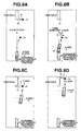
- Figs. 8A-8D show an example where the avoiding direction is set at the right side of the obstacle.
- suffixes "s" and "t" of the coordinates of Point P0 denote the coordinates of the coordinate system at the time when starting the avoidance traveling control; in other words, the suffixes denote the coordinates of an absolute coordinate system in which the substantial center of the stereo camera 4 is defined as an origin (an avoidance traveling start point) at this time, the longitudinal direction of the vehicle 1 is the T-axis, and the vehicle width direction thereof is the S-axis (similarly, hereinafter).
- time delay correction is performed for this P0(P0 s , P0 t ).
- the actual traveling locus for the time delay of the obstacle position (for the time delay in transmission and calculation before the images of the actual obstacle position are picked up through the stereo camera 4, processed by the environment recognition unit 5, and output to the control device 3) is estimated from the vehicle speed v from the vehicle speed sensor 7 and the yaw rate (d ⁇ /dt) from the yaw rate sensor 9, and the obstacle position based on the position of the vehicle 1 is again estimated and calculated.
- This correction is performed assuming that the traveling locus from the position of the vehicle 1 when the images of the obstacle are picked up to the actual position of the vehicle 1 forms a constant-speed and regular circular turn with respect to the sensor values detected when the vehicle 1 arrives at the actual position. More specifically, as shown in Fig. 7, it is assumed that the vehicle forms the regular circular turn with respect to the actual position from the position of the vehicle 1 when the images of the obstacle are picked up.
- the time delay correction is performed assuming that the obstacle position at the time of picking up the images of the obstacle is obtained based on these images when the vehicle 1 arrives at the actual position of the vehicle 1 due to the recognition delay.
- the yaw angle change ⁇ d of the vehicle 1 corresponding to the delay is calculated by the formula (1).
- ⁇ d (d ⁇ /dt) ⁇ td
- td is the recognition delay time (sec), which is set to, for example, 0.2 to 0.3.
- Xnew (Xold-xd) ⁇ cos ⁇ d + (zd - Zold) ⁇ sin ⁇ d
- Xo1d is the three-dimensional object position before correction (the X-coordinate value)
- Zold is the three-dimensional object position before correction (the Z-coordinate value).
- new P0 s and P0 t are calculated by substituting P0 s and P0 t of the point P0(P0 s , P0 t ) for Xold and Zold, respectively, in the above formulae (5) and (6).
- Point P1 P1s, P1t
- P2s, P2t the avoidance traveling target point P2
- P1 s P0 s + F where, F is a constant (e.g., 2m).
- P2 t P0 t /2
- the program advances to S107, and calculates the radius r2 by the formula (11), assuming that the passing locus to Point P2 is an arc.
- the sign (-) denotes the radius (absolute value) during the steering wheel turn to the left.
- r2 (P2 s 2 + P2 t 2 ) / (2 ⁇ P2 s )
- the target actual steering angle d2 is calculated by the formula (13) based on a first-order lag motion model of the vehicle.
- d2 (1/G0) ⁇ 2 + (1/G0) ⁇ Tr ⁇ (d ⁇ 2/dt)
- G0 is a steady-state yaw rate gain, and given by the formula (14).
- G0 (1/(1 + sf ⁇ v 2 )) ⁇ (v/L) sf is a stability factor
- L is a wheel base.
- the program advances to S108.
- the signal is output to the electric power steering control device 11, and the vehicle 1 is guided by realizing the target actual steering angle d2 calculated in S107 by known PID control or the like using the output signal from the steering wheel angle sensor 8 as the feedback value.
- the program advances to S109, and acquires the rear end position on the obstacle avoidance side, in other words, acquires Point P3 (P3 x , P3 z ) from obstacle position information from the environment recognition unit 5 (refer to Fig. 8B).
- the suffixes "x" and "z" of the coordinates of Point P3 indicate that the coordinates are different from the absolute coordinates of the S-T axis explained in S105, but the coordinates of the system with the vehicle as a reference in which a substantial center of the stereo camera 4 is an origin, the longitudinal direction of the vehicle 1 is the Z-axis, and the vehicle width direction is the X-axis (similarly, hereinafter).
- the time delay correction is performed.
- the actual traveling locus for the time delay of the obstacle position (the delay in transmission and calculation before the image of the actual obstacle position is picked up through the stereo camera 4, processed by the environment recognition unit 5, and output to the control device 3), is estimated from the vehicle speed v from the vehicle speed sensor 7, and the yaw rate (d ⁇ /dt) from the yaw rate sensor 9, and the obstacle position based on the vehicle 1 is again estimated and calculated.
- new P3 x and P3 z are calculated by substituting P3 x and P3 z of Point P3 (P3 x , P3 z ) for Xold and Zold, respectively, in the formulae (5) and (6).
- the program advances to S110, the yaw angle ⁇ of the vehicle 1 with the absolute coordinates of S-T axis as a reference is estimated by integrating the yaw rate (d ⁇ /dt) from the yaw rate sensor 9.
- the program advances to S111, and the position P4 (P4 s , P4 t ) of the vehicle 1 on the absolute coordinates of S-T axis is calculated based on P3 (P3 x , P3 z ) obtained in S109 and the yaw angle ⁇ of the vehicle 1 estimated in S110 by the formulae (16) and (17).
- Point P5 (P2 s - P4 s ) ⁇ cos ⁇ + (P4 t - P2 t ) ⁇ sin ⁇
- P5 z (P2 s - P4 s ) ⁇ sin ⁇ + (P2 t - P4 t ) ⁇ cos ⁇
- the program advances to S113, and the coordinate value P5 x of Point P5 is compared with the absolute value of the preset value Cx (for example, 0.2 m or 0.5 m).
- the program advances to S114 if P5 x ⁇
- the program completes processing in S114 or S115, and advances to S116.
- the signal is output to the electric power steering control device 11, and the vehicle 1 is guided by realizing the target actual steering angle d5 calculated in S114 or S115 by the known PID control or the like using the output signal from the steering wheel angle sensor 8 as the feedback value.
- the program advances to S117, and it is determined whether or not the vehicle 1 passes through Point P5. If the vehicle does not pass the point, repeat the processing from S109. If the vehicle passes the point, the program advances to S118.
- S118 it is determined whether or not a front end (a side wall) of the obstacle is recognized. If recognized, jump to S127. If not recognized, the program advances to S119.
- the program advances to S119, and it is determined whether or not a rear end of the obstacle is recognized. As a result of determination, if the rear end of the obstacle is not recognized, the program is exited. If the rear end of the obstacle is recognized, the program advances to S120.
- the program advances to S120, and acquires the rear end position on the obstacle avoidance side, in other words, Point P6(P6 x , P6 z ) from obstacle position information from the environment recognition unit 5 (refer to Fig. 8C).
- the actual traveling locus for the time delay of the obstacle position (the delay of transmission and calculation before the image of the actual obstacle position is picked up through the stereo camera 4, processed by the environment recognition unit 5, and output to the control device 3) is estimated from the vehicle speed v from the vehicle speed sensor 7 and the yaw rate (d ⁇ /dt) of the yaw rate sensor 9, and the obstacle position based on the position of the vehicle 1 is again estimated and calculated.
- new P6 x and P6 z are calculated by substituting P6 x and P6 z of Point P6(P6 x , P6 z ) for Xold and Zold, respectively, in the formulae (5) and (6).
- the program advances to S121, and the yaw angle ⁇ of the vehicle 1 is estimated by integrating the yaw rate (d ⁇ /dt) from the yaw rate sensor 9.
- the program advances to S122, the avoidance traveling reaching point P7(P7 x , P7 z ) is calculated as the target passing position by the formulae (23) and (24) from Point P6(P6 x , P6 z ) obtained in S120 and the yaw angle ⁇ of the vehicle 1 estimated in S121.
- Point P7 corresponds to Point P1.
- P7 x F ⁇ cos ⁇ + P6 x
- P7 z F ⁇ sin ⁇ + P6 z
- the program advances to S123, and compares the coordinate value P7 x of Point P7 with the absolute value of the preset value Cx (for example, 0.2 m or 0.5 m). As a result of comparison, if P7 x ⁇
- the program completes processing in S124 or S125, and advances to S126.
- the signal is output to the electric power steering control device 11, and the vehicle 1 is guided by realizing the target actual steering angle d7 calculated in S124 or S125 by the known PID control or the like using the output signal from the steering wheel angle sensor 8 as the feedback value, and return to S118.
- the vehicle 1 is guided by setting the turning direction of the vehicle 1 in the direction of leaving away from the obstacle with the avoidance traveling target point P2 or P5 as the target passing position in S107 and S116, and if Point P2 or Point P5 is passed, the vehicle 1 is guide by switching the steering direction of the vehicle 1 to the opposite direction in S126.
- Point P2 or Point P5 is a point at which the turning direction of the vehicle 1 is switched to the opposite direction with respect to the turning direction of the vehicle 1 from the avoidance traveling start point to Point P2 or Point P5.
- the front end (the side wall) of the obstacle is recognized in S118, and the program advances to S127.
- the program acquires the front end position on the obstacle avoidance side, in other words, Point P8 (P8 x ,P8 z ) from obstacle position information from the environment recognition unit 5 (refer to Fig. 8D).
- Point P8 After acquiring Point P8 (P8 x , P8 z ), perform the time delay correction.
- the delay correction as described in S105, the actual traveling locus for the time delay of the obstacle position (the delay of transmission and calculation before the image of the actual obstacle position is picked up through the stereo camera 4, processed by the environment recognition unit 5, and output to the control device 3) is estimated from the vehicle speed v from the vehicle speed sensor 7 and the yaw rate (d ⁇ /dt) of the yaw rate sensor 9, and the obstacle position based on the position of the vehicle 1 is again estimated and calculated.
- new P8 x and P8 z are calculated by substituting P8 x and P8 z of Point P8(P8 x , P8 z ) for Xold and Zold, respectively, in the formulae (5) and (6).
- the program advances to S129, and compares the coordinate value P9 x of Point P9 with the absolute value of the preset value Cx (for example, 0.2 m or 0.5 m). As a result of comparison, if P9 x ⁇
- the program completes processing in S130 or S131, and advances to S132.
- the signal is output to the electric power steering control device 11, and the vehicle 1 is guided by realizing the target actual steering angle d9 calculated in S130 or S131 by the known PID control or the like using the output signal from the steering wheel angle sensor 8 as the feedback value.
- the program advances to S133, and it is determined whether or not the front end (the side wall) of the obstacle is recognized. If recognized, processing from S127 is repeated. If not recognized, the program is exited.
- Point P7 is the avoidance traveling reaching point
- Points P2 and P5 are avoidance traveling target points
- Point P9 is the final avoidance target point.
- Fig. 6 shows the flowchart of the avoiding direction determination routine executed in S102 above.
- S201 it is determined whether or not other obstacles are present on both sides of the obstacle to be avoided. As a result of determination, if obstacles are present, execute the processing in S202 to S207. If no obstacles are present, execute the processing in S208 to S215.
- the program advances to S202, and it is determined whether or not the other obstacles than the obstacle to be avoided are both pedestrians. As a result of this determination, if it is determined that pedestrians are present on both sides, the program advances to S203, determines the stop of avoidance control, and exits the routine. On the other hand, if it is determined that pedestrians are not present on both sides, the program advances to S204.
- S204 it is determined whether or not one of the other obstacles than the obstacle to be avoided is a pedestrian. As a result of the determination, if it is determined that one of the other obstacles is a pedestrian, the program advances to S205, sets an avoidance path in the direction opposite to the side on which the pedestrian is present, and exits the routine.
- the program advances to S206, and determines on which side an avoidance space is present.
- the program advances to S203, determines the stop of avoidance control, and exits the routine.
- the program advances to S207, determines that avoidance is performed to the side with a larger obstacle-to-obstacle distance between the obstacle to be avoided and the other obstacle, and exits the routine.
- the program advances to S209, determines avoidance to the side on which no other obstacle is present, and exits the routine.
- the program advances to S210, and it is determined whether or not an oncoming vehicle is approaching one side of the obstacle to be avoided.
- the program advances to S211, determines avoidance to the side on which no oncoming vehicle is present, and exits the routine.
- the program advances to S212, and it is determined whether or not obstacles are approaching from right and left sides at the rear of the vehicle 1.
- the program advances to S203, determines the stop of avoidance control, and exits the routine.
- the program advances to S213.
- the program advances to S215, determines avoidance to a side in which the transverse distance between the obstacle end point and the vehicle 1 is smaller, and exits the routine.
- the target passing position includes only the avoidance traveling reaching point P7 of the obstacle to be avoided, the avoidance traveling target points P2 and P5, and the final avoidance target point P9
- the vehicle is guided based on the target actual steering angle which is the vehicle motion parameter obtained according to the vehicle motion model with the target passing position as a target, and the obstacle can be smoothly, efficiently and stably avoided based on the actual behavior of the vehicle while controlling the increase of the number of operations to a minimum.
- avoidance traveling is described when the avoidance traveling target point P5 is at the target passing position, and the obstacle is a mobile three-dimensional object.
- the position of the vehicle 1 during the avoidance traveling with the avoidance traveling target point P5 as the target passing position is estimated by calculating the position of the vehicle 1 in the absolute coordinates from the position of the obstacle obtained with the avoidance traveling start time as a reference, obstacle position information obtained during the avoidance traveling, and the yaw angle of the vehicle 1 calculated by integrating the yaw rate (d ⁇ /dt) from the yaw rate sensor 9. If the obstacle moves, the control device 3 does not recognize that the obstacle is moving, but recognizes that the positional coordinates of the obstacle in the absolute coordinate system are matched with the positional coordinates of the obstacle obtained during the avoidance traveling.
- the position of the vehicle 1 is estimated as the position in the absolute coordinate system while maintaining the positional relationship with the obstacle.
- the position of the obstacle and the position of the vehicle 1 are estimated to the positions different from the actual positions by the movement of the obstacle.
- the avoidance traveling target point P5 in the absolute coordinate system is set to the position different by the movement of the obstacle similar to the estimated position of the vehicle 1, and the control device 3 can guide the vehicle 1 with the avoidance traveling target point P5 as the target passing position.
- the actual obstacle position or the actual position of the vehicle 1 need not be calculated by detecting the movement or the like of the obstacle.
- the position of the avoidance traveling target point P5 with respect to the vehicle 1 is adequately set according to obstacle position information obtained during the avoidance traveling, and the vehicle 1 can be guided.
- the target passing position is adequately set according to obstacle position information obtained during the avoidance traveling, and the vehicle 1 can be guided even if the obstacle is a mobile three-dimensional object.
- the laser radar device 6 is used to detect approach of the obstacles from right and left sides at the rear of the vehicle 1.
- approach may be detected by information obtained from a CCD camera or an infrastructure facing backwardly.
- the center of the pair of stereo cameras 4 is set to be the center of the coordinate system to perform each operation.
- the control value of more excellent accuracy can be obtained if each operation is performed by adding the distance from the position of the center of gravity to the center of the pair of stereo cameras 4 to each coordinate value considering the positional deviation to the center of gravity of the vehicle 1.
- transition from the recognizing state of the obstacle to the non-recognizing state, or transition from the non-recognizing state to the recognizing state can be reliably performed if determination is performed by continuous several frames (for example, three frames) of the obtained images.
- the obstacle can be smoothly, efficiently and stably avoided based on the actual behavior of the vehicle while keeping an increase in the number of operations to a minimum.
Landscapes
- Engineering & Computer Science (AREA)
- Chemical & Material Sciences (AREA)
- Combustion & Propulsion (AREA)
- Transportation (AREA)
- Mechanical Engineering (AREA)
- Physics & Mathematics (AREA)
- Mathematical Physics (AREA)
- Control Of Driving Devices And Active Controlling Of Vehicle (AREA)
- Steering Control In Accordance With Driving Conditions (AREA)
- Traffic Control Systems (AREA)
Abstract
Description
Claims (10)
- A vehicle traveling control device characterized by comprising:wherein the control means (3) sets an avoidance traveling start point to start the avoidance traveling, an avoidance traveling reaching point on the obstacle side based on the position of the obstacle, and an avoidance traveling target point between the avoidance traveling start point and the avoidance traveling reaching point: sets vehicle motion parameters based on a vehicle motion model with the avoidance traveling target point and the avoidance traveling reaching point as target passing positions: and guides the vehicle (1) so that the turning direction of the vehicle (1) is switched to the opposite direction at the avoidance traveling target point with respect to the turning direction of the vehicle (1) from the avoidance traveling start point to the avoidance traveling target point.object detection means (5 and 6) to detect an object in a traveling environment;obstacle recognition means (5) to recognize an obstacle to form a traveling obstacle of a vehicle (1) from among the objects detected by the object detection means (5 and 6); andcontrol means (3) to guide the vehicle (1) so as to turnably avoid the obstacle recognized by the obstacle recognition means (5);
- The vehicle traveling control device according to Claim 1, characterized in that the control means (3) sets a final avoidance target point to avoid the obstacle, sets vehicle motion parameters based on a vehicle motion model with the final avoidance target point as a target passing position, and guides the vehicle (1) to the target passing position.
- The vehicle traveling control device according to Claim 1 or Claim 2, characterized in that the control means (3) estimates a present position of the vehicle (1) based on positional information of the obstacle obtained with the avoidance traveling start point as a reference, presently obtained positional information of the obstacle from the obstacle recognition means (5), and the state of the motion of the vehicle when the vehicle is guided with the avoidance traveling target point as the target passing position, estimates a new avoidance traveling target point by the avoidance traveling target point set with the avoidance traveling start point as a reference, the present position of the vehicle, and the state of the motion of the vehicle, and sets the new avoidance traveling target point to be at the target passing position.
- The vehicle traveling control device according to any one of Claims 1 to 3, characterized in that the avoidance traveling reaching point is set based on positional information of the obstacle from the obstacle recognition means (5) obtained when guiding the vehicle (1) and the state of the motion of the vehicle.
- The vehicle traveling control device according to any one of Claims 1 to 4, characterized in that the control means (3) sets a steering angle to be substantially zero when the transverse deviation between the target passing position and the position of the vehicle (1) does not exceed a preset value.
- The vehicle traveling control device according to any one of Claims 1 to 5, characterized in that the control means (3) cancels the guiding of the vehicle (1) if the object detection means (5 and 6) detects that pedestrians are present on both sides of the obstacle.
- The vehicle traveling control device according to any one of Claims 1 to 6, characterized in that the control means (3) guides the vehicle (1) to the side on which no pedestrian is present if the object detection means (5 and 6) detects that a pedestrian is present on one side of the obstacle.
- The vehicle traveling control device according to any one of Claims 1 to 7, characterized in that the control means (3) guides the vehicle (1) to the side on which no oncoming vehicle is present if the object detection means (5 and 6) detects the oncoming vehicle on either side of the obstacle.
- The vehicle traveling control device according to any one of Claims 1 to 8, characterized in that the control means (3) cancels the guiding of the vehicle (1) if the object detection means (5 and 6) detects that a second obstacle different from the above obstacle approaches from both backward sides of the vehicle (1).
- The vehicle traveling control device according to any one of Claims 1 to 9, characterized in that the control means (3) guides the vehicle (1) to the side on which a second obstacle does not approach if the object detection means (5 and 6) detects that the second obstacle different from the above obstacle approaches from either backward side of the vehicle (1).
Applications Claiming Priority (2)
| Application Number | Priority Date | Filing Date | Title |
|---|---|---|---|
| JP2003408326A JP4647201B2 (en) | 2003-12-05 | 2003-12-05 | Vehicle travel control device |
| JP2003408326 | 2003-12-05 |
Publications (3)
| Publication Number | Publication Date |
|---|---|
| EP1538068A2 true EP1538068A2 (en) | 2005-06-08 |
| EP1538068A3 EP1538068A3 (en) | 2006-06-07 |
| EP1538068B1 EP1538068B1 (en) | 2010-10-13 |
Family
ID=34464041
Family Applications (1)
| Application Number | Title | Priority Date | Filing Date |
|---|---|---|---|
| EP04028471A Expired - Lifetime EP1538068B1 (en) | 2003-12-05 | 2004-12-01 | Collision avoidance control for vehicles |
Country Status (4)
| Country | Link |
|---|---|
| US (1) | US7243026B2 (en) |
| EP (1) | EP1538068B1 (en) |
| JP (1) | JP4647201B2 (en) |
| DE (1) | DE602004029543D1 (en) |
Cited By (6)
| Publication number | Priority date | Publication date | Assignee | Title |
|---|---|---|---|---|
| WO2007023103A1 (en) * | 2005-08-23 | 2007-03-01 | Siemens Aktiengesellschaft | Lane-departure warning and/or lane-keeping system |
| EP1777143A1 (en) * | 2005-10-20 | 2007-04-25 | Volkswagen Aktiengesellschaft | Lane-change assistant |
| EP2042962A1 (en) * | 2007-09-27 | 2009-04-01 | Hitachi Ltd. | Driving support system |
| CN104655039A (en) * | 2015-03-16 | 2015-05-27 | 赵佑民 | Laser image detection device and method of air pre-heater rotor deformation |
| CN105539586A (en) * | 2014-08-29 | 2016-05-04 | 通用汽车环球科技运作有限责任公司 | Unified motion planner for autonomous driving vehicle in avoiding the moving obstacle |
| CN112572472A (en) * | 2020-12-08 | 2021-03-30 | 重庆大学 | Automatic driving collision prediction method based on Frenet coordinate system |
Families Citing this family (54)
| Publication number | Priority date | Publication date | Assignee | Title |
|---|---|---|---|---|
| US7974778B2 (en) * | 2004-09-17 | 2011-07-05 | Honda Motor Co., Ltd. | Vehicular control object determination system and vehicular travel locus estimation system |
| US7751976B2 (en) * | 2005-08-26 | 2010-07-06 | Sikorsky Aircraft Corporation | Rotary wing aircraft flight control system with a proximity cueing and avoidance system |
| EP1926654B1 (en) * | 2005-09-15 | 2009-12-09 | Continental Teves AG & Co. oHG | Method and device for steering a motor vehicle |
| JP2007124609A (en) * | 2005-09-28 | 2007-05-17 | Nissan Motor Co Ltd | Vehicle surrounding image providing device |
| US7864032B2 (en) * | 2005-10-06 | 2011-01-04 | Fuji Jukogyo Kabushiki Kaisha | Collision determination device and vehicle behavior control device |
| US20100238066A1 (en) * | 2005-12-30 | 2010-09-23 | Valeo Raytheon Systems, Inc. | Method and system for generating a target alert |
| JP2007309670A (en) * | 2006-05-16 | 2007-11-29 | Toyota Motor Corp | Vehicle position detection device |
| JP4793094B2 (en) * | 2006-05-17 | 2011-10-12 | 株式会社デンソー | Driving environment recognition device |
| US8139109B2 (en) * | 2006-06-19 | 2012-03-20 | Oshkosh Corporation | Vision system for an autonomous vehicle |
| US8947531B2 (en) * | 2006-06-19 | 2015-02-03 | Oshkosh Corporation | Vehicle diagnostics based on information communicated between vehicles |
| JP4811154B2 (en) * | 2006-06-29 | 2011-11-09 | トヨタ自動車株式会社 | Vehicle traveling device |
| JP5016889B2 (en) * | 2006-10-11 | 2012-09-05 | 日立オートモティブシステムズ株式会社 | Preventive safety device |
| JP4846545B2 (en) * | 2006-11-29 | 2011-12-28 | 株式会社デンソー | Driving assistance device |
| US7979199B2 (en) | 2007-01-10 | 2011-07-12 | Honeywell International Inc. | Method and system to automatically generate a clearance request to deviate from a flight plan |
| JP2008168784A (en) * | 2007-01-11 | 2008-07-24 | Fuji Heavy Ind Ltd | Vehicle travel control device |
| JP4975503B2 (en) * | 2007-04-06 | 2012-07-11 | 本田技研工業株式会社 | Legged mobile robot |
| KR100854766B1 (en) * | 2007-04-27 | 2008-08-27 | 주식회사 만도 | Parking space detection method using distance sensor |
| JP2009096273A (en) * | 2007-10-16 | 2009-05-07 | Hitachi Ltd | Collision avoidance control device |
| US8452053B2 (en) * | 2008-04-24 | 2013-05-28 | GM Global Technology Operations LLC | Pixel-based texture-rich clear path detection |
| US8170739B2 (en) * | 2008-06-20 | 2012-05-01 | GM Global Technology Operations LLC | Path generation algorithm for automated lane centering and lane changing control system |
| JP5509554B2 (en) * | 2008-08-08 | 2014-06-04 | 日産自動車株式会社 | Vehicle travel support device and vehicle travel support method |
| JP5070171B2 (en) * | 2008-09-19 | 2012-11-07 | 日立オートモティブシステムズ株式会社 | Vehicle control device |
| JP5369694B2 (en) | 2009-01-16 | 2013-12-18 | トヨタ自動車株式会社 | Maneuvering support device |
| JP2010179761A (en) * | 2009-02-05 | 2010-08-19 | Nissan Motor Co Ltd | Device and method for supporting driving operation |
| US8577551B2 (en) * | 2009-08-18 | 2013-11-05 | Crown Equipment Corporation | Steer control maneuvers for materials handling vehicles |
| WO2011080830A1 (en) * | 2009-12-28 | 2011-07-07 | トヨタ自動車株式会社 | Driving assistance device |
| CN102712318B (en) * | 2010-01-15 | 2015-04-08 | 丰田自动车株式会社 | Vehicle control device |
| US9083861B2 (en) | 2010-04-09 | 2015-07-14 | Wabtec Holding Corp. | Visual data collection system for a train |
| US20120022739A1 (en) * | 2010-07-20 | 2012-01-26 | Gm Global Technology Operations, Inc. | Robust vehicular lateral control with front and rear cameras |
| JP2012079118A (en) * | 2010-10-01 | 2012-04-19 | Toyota Motor Corp | Drive-supporting apparatus and drive-supporting method |
| US8459619B2 (en) | 2010-10-24 | 2013-06-11 | Oshkosh Corporation | Gas spring control system and method |
| JP5811189B2 (en) * | 2011-12-28 | 2015-11-11 | トヨタ自動車株式会社 | Obstacle determination device |
| JP5993692B2 (en) * | 2012-09-28 | 2016-09-14 | 富士重工業株式会社 | vehicle |
| US9304203B1 (en) * | 2013-03-13 | 2016-04-05 | Google Inc. | Methods, devices, and systems for improving dynamic range of signal receiver |
| EP2942251B1 (en) | 2014-05-08 | 2017-04-05 | Volvo Car Corporation | Method for providing an object prediction representation |
| EP2942250B1 (en) * | 2014-05-08 | 2017-02-01 | Volvo Car Corporation | Method for determining an evasive path for a host vehicle |
| BR112017003659B1 (en) * | 2014-08-28 | 2022-01-18 | Nissan Motor Co., Ltd | ROUTE CONTROL DEVICE AND ROUTE CONTROL METHOD |
| KR101628503B1 (en) * | 2014-10-27 | 2016-06-08 | 현대자동차주식회사 | Driver assistance apparatus and method for operating thereof |
| US10026324B2 (en) | 2014-11-04 | 2018-07-17 | Honeywell International Inc. | Systems and methods for enhanced adoptive validation of ATC clearance requests |
| EP3115856A1 (en) * | 2015-07-09 | 2017-01-11 | Siemens Aktiengesellschaft | Trajectory determining method for in addition to secondary processing movements |
| US9881219B2 (en) * | 2015-10-07 | 2018-01-30 | Ford Global Technologies, Llc | Self-recognition of autonomous vehicles in mirrored or reflective surfaces |
| CN105857294B (en) * | 2016-05-04 | 2018-12-04 | 常州工学院 | Automobile lane changing collision avoidance control method |
| US11307591B2 (en) | 2017-01-24 | 2022-04-19 | Honda Motor Co., Ltd. | Vehicle control system, vehicle control method, and vehicle control program |
| US20180341822A1 (en) * | 2017-05-26 | 2018-11-29 | Dura Operating, Llc | Method and system for classifying objects in a perception scene graph by using a scene-detection-schema |
| EP3413083B1 (en) * | 2017-06-09 | 2020-03-11 | Veoneer Sweden AB | A vehicle system for detection of oncoming vehicles |
| JP7132713B2 (en) | 2017-12-28 | 2022-09-07 | 株式会社Soken | Vehicle cruise control device, vehicle cruise control system, and vehicle cruise control method |
| CN109191487B (en) * | 2018-08-30 | 2022-03-25 | 阿波罗智能技术(北京)有限公司 | Unmanned vehicle-based collision detection method, device, equipment and storage medium |
| KR102387603B1 (en) * | 2018-10-24 | 2022-04-18 | 주식회사 스프링클라우드 | Apparatus and method for generating an obstacle avoidance path in an autonomous vehicle |
| KR102706256B1 (en) * | 2019-07-08 | 2024-09-12 | 현대자동차주식회사 | Method and system for calibrating road surface information detected electronic control suspension |
| CN110816527A (en) * | 2019-11-27 | 2020-02-21 | 奇瑞汽车股份有限公司 | A vehicle night vision security method and system |
| CN110843775B (en) * | 2019-11-30 | 2022-04-01 | 的卢技术有限公司 | Obstacle identification method based on pressure sensor |
| KR102844524B1 (en) | 2020-08-11 | 2025-08-12 | 크라운 이큅먼트 코포레이션 | remote control device |
| TWI758980B (en) | 2020-11-30 | 2022-03-21 | 財團法人金屬工業研究發展中心 | Environment perception device and method of mobile vehicle |
| CN113428141B (en) * | 2021-07-15 | 2022-12-09 | 东风汽车集团股份有限公司 | Intelligent detection method and system for timely response of emergency cut-in of front vehicle |
Family Cites Families (12)
| Publication number | Priority date | Publication date | Assignee | Title |
|---|---|---|---|---|
| JPS59111508A (en) | 1982-12-16 | 1984-06-27 | Agency Of Ind Science & Technol | Automatic car guiding method using point follow-up system |
| JP3197307B2 (en) * | 1991-10-14 | 2001-08-13 | マツダ株式会社 | Travel control device for mobile vehicles |
| JP2853077B2 (en) | 1993-09-17 | 1999-02-03 | 本田技研工業株式会社 | Self-driving vehicle |
| JPH1031799A (en) * | 1996-07-15 | 1998-02-03 | Toyota Motor Corp | Automatic driving control device |
| JPH10308000A (en) * | 1997-05-09 | 1998-11-17 | Nissan Motor Co Ltd | Vehicle control device |
| US6269308B1 (en) | 1998-08-20 | 2001-07-31 | Honda Giken Kogyo Kabushiki Kaisha | Safety running system for vehicle |
| JP4097844B2 (en) * | 1999-05-20 | 2008-06-11 | 株式会社小松製作所 | Moving body guidance device |
| JP2000339029A (en) * | 1999-05-31 | 2000-12-08 | Komatsu Ltd | Vehicle interference prevention device |
| JP2001255937A (en) * | 2000-03-10 | 2001-09-21 | Toshiba Corp | Automatic cruise control system for vehicles |
| DE10012737B4 (en) | 2000-03-16 | 2007-09-06 | Daimlerchrysler Ag | Device for carrying out a lane change by a motor vehicle |
| DE10036276A1 (en) | 2000-07-26 | 2002-02-07 | Daimler Chrysler Ag | Automatic braking and steering system for a vehicle |
| US20050128063A1 (en) * | 2003-11-28 | 2005-06-16 | Denso Corporation | Vehicle driving assisting apparatus |
-
2003
- 2003-12-05 JP JP2003408326A patent/JP4647201B2/en not_active Expired - Fee Related
-
2004
- 2004-11-30 US US10/998,946 patent/US7243026B2/en not_active Expired - Fee Related
- 2004-12-01 DE DE602004029543T patent/DE602004029543D1/en not_active Expired - Lifetime
- 2004-12-01 EP EP04028471A patent/EP1538068B1/en not_active Expired - Lifetime
Cited By (10)
| Publication number | Priority date | Publication date | Assignee | Title |
|---|---|---|---|---|
| WO2007023103A1 (en) * | 2005-08-23 | 2007-03-01 | Siemens Aktiengesellschaft | Lane-departure warning and/or lane-keeping system |
| EP1777143A1 (en) * | 2005-10-20 | 2007-04-25 | Volkswagen Aktiengesellschaft | Lane-change assistant |
| EP2042962A1 (en) * | 2007-09-27 | 2009-04-01 | Hitachi Ltd. | Driving support system |
| US8346436B2 (en) | 2007-09-27 | 2013-01-01 | Hitachi, Ltd. | Driving support system |
| CN105539586A (en) * | 2014-08-29 | 2016-05-04 | 通用汽车环球科技运作有限责任公司 | Unified motion planner for autonomous driving vehicle in avoiding the moving obstacle |
| CN105539586B (en) * | 2014-08-29 | 2018-10-26 | 通用汽车环球科技运作有限责任公司 | Vehicle for autonomous driving hides the unified motion planning of moving obstacle |
| CN104655039A (en) * | 2015-03-16 | 2015-05-27 | 赵佑民 | Laser image detection device and method of air pre-heater rotor deformation |
| CN104655039B (en) * | 2015-03-16 | 2017-04-12 | 赵佑民 | Laser image detection device and method of air pre-heater rotor deformation |
| CN112572472A (en) * | 2020-12-08 | 2021-03-30 | 重庆大学 | Automatic driving collision prediction method based on Frenet coordinate system |
| CN112572472B (en) * | 2020-12-08 | 2021-12-14 | 重庆大学 | A Collision Prediction Method for Autonomous Driving Based on Frenet Coordinate System |
Also Published As
| Publication number | Publication date |
|---|---|
| US20050125155A1 (en) | 2005-06-09 |
| JP2005173663A (en) | 2005-06-30 |
| JP4647201B2 (en) | 2011-03-09 |
| US7243026B2 (en) | 2007-07-10 |
| EP1538068B1 (en) | 2010-10-13 |
| EP1538068A3 (en) | 2006-06-07 |
| DE602004029543D1 (en) | 2010-11-25 |
Similar Documents
| Publication | Publication Date | Title |
|---|---|---|
| EP1538068B1 (en) | Collision avoidance control for vehicles | |
| JP4021344B2 (en) | Vehicle driving support device | |
| US7711466B2 (en) | Vehicle driving control unit | |
| JP4970156B2 (en) | Vehicle driving support device | |
| JP4628683B2 (en) | Pedestrian detection device and vehicle driving support device including the pedestrian detection device | |
| US10580303B2 (en) | Collision avoidance device | |
| US10093316B2 (en) | Vehicle traveling control device | |
| CN110271543B (en) | Vehicle control device, vehicle control method, and storage medium | |
| JP4173292B2 (en) | Driving assistance device for vehicle | |
| JP3358709B2 (en) | Driving support device for vehicles | |
| JP4949063B2 (en) | Vehicle driving support device | |
| JP2012183867A (en) | Vehicle driving support apparatus | |
| US7663475B2 (en) | Vehicle surrounding monitoring system | |
| JP2005186813A (en) | Vehicle driving support device | |
| WO2019039275A1 (en) | Vehicle control device | |
| CN112429002A (en) | Vehicle control device, vehicle control method, and storage medium | |
| JP2004355324A (en) | Contact avoidance control device for vehicles | |
| JPH1139598A (en) | Collision preventing device for vehicle | |
| JP6535537B2 (en) | Driving support device for vehicle | |
| JP2005010893A (en) | Vehicle contact avoidance control device | |
| JP2005081999A (en) | Vehicle driving support device | |
| JP4294450B2 (en) | Vehicle driving support device | |
| JP4237686B2 (en) | Vehicle driving support device | |
| JP4628596B2 (en) | Vehicle driving support device | |
| JP4807753B2 (en) | Vehicle driving support device |
Legal Events
| Date | Code | Title | Description |
|---|---|---|---|
| PUAI | Public reference made under article 153(3) epc to a published international application that has entered the european phase |
Free format text: ORIGINAL CODE: 0009012 |
|
| AK | Designated contracting states |
Kind code of ref document: A2 Designated state(s): AT BE BG CH CY CZ DE DK EE ES FI FR GB GR HU IE IS IT LI LT LU MC NL PL PT RO SE SI SK TR |
|
| AX | Request for extension of the european patent |
Extension state: AL BA HR LV MK YU |
|
| PUAL | Search report despatched |
Free format text: ORIGINAL CODE: 0009013 |
|
| AK | Designated contracting states |
Kind code of ref document: A3 Designated state(s): AT BE BG CH CY CZ DE DK EE ES FI FR GB GR HU IE IS IT LI LT LU MC NL PL PT RO SE SI SK TR |
|
| AX | Request for extension of the european patent |
Extension state: AL BA HR LV MK YU |
|
| 17P | Request for examination filed |
Effective date: 20060703 |
|
| 17Q | First examination report despatched |
Effective date: 20060810 |
|
| AKX | Designation fees paid |
Designated state(s): DE |
|
| GRAP | Despatch of communication of intention to grant a patent |
Free format text: ORIGINAL CODE: EPIDOSNIGR1 |
|
| RIN1 | Information on inventor provided before grant (corrected) |
Inventor name: KUDO, SHINYAC/O FUJI JUKOGYO KABUSHIKI KAISHA |
|
| GRAS | Grant fee paid |
Free format text: ORIGINAL CODE: EPIDOSNIGR3 |
|
| GRAA | (expected) grant |
Free format text: ORIGINAL CODE: 0009210 |
|
| AK | Designated contracting states |
Kind code of ref document: B1 Designated state(s): DE |
|
| REF | Corresponds to: |
Ref document number: 602004029543 Country of ref document: DE Date of ref document: 20101125 Kind code of ref document: P |
|
| PLBE | No opposition filed within time limit |
Free format text: ORIGINAL CODE: 0009261 |
|
| STAA | Information on the status of an ep patent application or granted ep patent |
Free format text: STATUS: NO OPPOSITION FILED WITHIN TIME LIMIT |
|
| 26N | No opposition filed |
Effective date: 20110714 |
|
| REG | Reference to a national code |
Ref country code: DE Ref legal event code: R097 Ref document number: 602004029543 Country of ref document: DE Effective date: 20110714 |
|
| REG | Reference to a national code |
Ref country code: DE Ref legal event code: R082 Ref document number: 602004029543 Country of ref document: DE Representative=s name: VOSSIUS & PARTNER PATENTANWAELTE RECHTSANWAELT, DE Ref country code: DE Ref legal event code: R081 Ref document number: 602004029543 Country of ref document: DE Owner name: SUBARU CORPORATION, JP Free format text: FORMER OWNER: FUJI JUKOGYO K.K., TOKIO/TOKYO, JP |
|
| REG | Reference to a national code |
Ref country code: DE Ref legal event code: R084 Ref document number: 602004029543 Country of ref document: DE |
|
| PGFP | Annual fee paid to national office [announced via postgrant information from national office to epo] |
Ref country code: DE Payment date: 20211210 Year of fee payment: 18 |
|
| REG | Reference to a national code |
Ref country code: DE Ref legal event code: R119 Ref document number: 602004029543 Country of ref document: DE |
|
| PG25 | Lapsed in a contracting state [announced via postgrant information from national office to epo] |
Ref country code: DE Free format text: LAPSE BECAUSE OF NON-PAYMENT OF DUE FEES Effective date: 20230701 |