EP1538029A1 - Floating contact assembly for a steering wheel - Google Patents
Floating contact assembly for a steering wheel Download PDFInfo
- Publication number
- EP1538029A1 EP1538029A1 EP04257065A EP04257065A EP1538029A1 EP 1538029 A1 EP1538029 A1 EP 1538029A1 EP 04257065 A EP04257065 A EP 04257065A EP 04257065 A EP04257065 A EP 04257065A EP 1538029 A1 EP1538029 A1 EP 1538029A1
- Authority
- EP
- European Patent Office
- Prior art keywords
- circuit board
- steering wheel
- contact
- contacts
- arm
- Prior art date
- Legal status (The legal status is an assumption and is not a legal conclusion. Google has not performed a legal analysis and makes no representation as to the accuracy of the status listed.)
- Granted
Links
- 230000000712 assembly Effects 0.000 claims abstract description 15
- 238000000429 assembly Methods 0.000 claims abstract description 15
- 238000004519 manufacturing process Methods 0.000 description 3
- 239000004020 conductor Substances 0.000 description 2
- 230000003247 decreasing effect Effects 0.000 description 2
- 230000013011 mating Effects 0.000 description 1
- 230000004048 modification Effects 0.000 description 1
- 238000012986 modification Methods 0.000 description 1
Images


Classifications
-
- B—PERFORMING OPERATIONS; TRANSPORTING
- B60—VEHICLES IN GENERAL
- B60R—VEHICLES, VEHICLE FITTINGS, OR VEHICLE PARTS, NOT OTHERWISE PROVIDED FOR
- B60R16/00—Electric or fluid circuits specially adapted for vehicles and not otherwise provided for; Arrangement of elements of electric or fluid circuits specially adapted for vehicles and not otherwise provided for
- B60R16/02—Electric or fluid circuits specially adapted for vehicles and not otherwise provided for; Arrangement of elements of electric or fluid circuits specially adapted for vehicles and not otherwise provided for electric constitutive elements
- B60R16/023—Electric or fluid circuits specially adapted for vehicles and not otherwise provided for; Arrangement of elements of electric or fluid circuits specially adapted for vehicles and not otherwise provided for electric constitutive elements for transmission of signals between vehicle parts or subsystems
- B60R16/027—Electric or fluid circuits specially adapted for vehicles and not otherwise provided for; Arrangement of elements of electric or fluid circuits specially adapted for vehicles and not otherwise provided for electric constitutive elements for transmission of signals between vehicle parts or subsystems between relatively movable parts of the vehicle, e.g. between steering wheel and column
-
- B—PERFORMING OPERATIONS; TRANSPORTING
- B60—VEHICLES IN GENERAL
- B60Q—ARRANGEMENT OF SIGNALLING OR LIGHTING DEVICES, THE MOUNTING OR SUPPORTING THEREOF OR CIRCUITS THEREFOR, FOR VEHICLES IN GENERAL
- B60Q1/00—Arrangement of optical signalling or lighting devices, the mounting or supporting thereof or circuits therefor
- B60Q1/0076—Switches therefor
- B60Q1/0082—Switches therefor mounted on the steering wheel
-
- B—PERFORMING OPERATIONS; TRANSPORTING
- B62—LAND VEHICLES FOR TRAVELLING OTHERWISE THAN ON RAILS
- B62D—MOTOR VEHICLES; TRAILERS
- B62D1/00—Steering controls, i.e. means for initiating a change of direction of the vehicle
- B62D1/02—Steering controls, i.e. means for initiating a change of direction of the vehicle vehicle-mounted
- B62D1/04—Hand wheels
- B62D1/046—Adaptations on rotatable parts of the steering wheel for accommodation of switches
-
- H—ELECTRICITY
- H01—ELECTRIC ELEMENTS
- H01H—ELECTRIC SWITCHES; RELAYS; SELECTORS; EMERGENCY PROTECTIVE DEVICES
- H01H1/00—Contacts
- H01H1/58—Electric connections to or between contacts; Terminals
- H01H1/5805—Connections to printed circuits
-
- B—PERFORMING OPERATIONS; TRANSPORTING
- B60—VEHICLES IN GENERAL
- B60R—VEHICLES, VEHICLE FITTINGS, OR VEHICLE PARTS, NOT OTHERWISE PROVIDED FOR
- B60R21/00—Arrangements or fittings on vehicles for protecting or preventing injuries to occupants or pedestrians in case of accidents or other traffic risks
- B60R21/02—Occupant safety arrangements or fittings, e.g. crash pads
- B60R21/16—Inflatable occupant restraints or confinements designed to inflate upon impact or impending impact, e.g. air bags
- B60R21/20—Arrangements for storing inflatable members in their non-use or deflated condition; Arrangement or mounting of air bag modules or components
- B60R21/203—Arrangements for storing inflatable members in their non-use or deflated condition; Arrangement or mounting of air bag modules or components in steering wheels or steering columns
- B60R21/2035—Arrangements for storing inflatable members in their non-use or deflated condition; Arrangement or mounting of air bag modules or components in steering wheels or steering columns using modules containing inflator, bag and cover attachable to the steering wheel as a complete sub-unit
-
- H—ELECTRICITY
- H05—ELECTRIC TECHNIQUES NOT OTHERWISE PROVIDED FOR
- H05K—PRINTED CIRCUITS; CASINGS OR CONSTRUCTIONAL DETAILS OF ELECTRIC APPARATUS; MANUFACTURE OF ASSEMBLAGES OF ELECTRICAL COMPONENTS
- H05K3/00—Apparatus or processes for manufacturing printed circuits
- H05K3/36—Assembling printed circuits with other printed circuits
- H05K3/361—Assembling flexible printed circuits with other printed circuits
- H05K3/365—Assembling flexible printed circuits with other printed circuits by abutting, i.e. without alloying process
-
- Y—GENERAL TAGGING OF NEW TECHNOLOGICAL DEVELOPMENTS; GENERAL TAGGING OF CROSS-SECTIONAL TECHNOLOGIES SPANNING OVER SEVERAL SECTIONS OF THE IPC; TECHNICAL SUBJECTS COVERED BY FORMER USPC CROSS-REFERENCE ART COLLECTIONS [XRACs] AND DIGESTS
- Y10—TECHNICAL SUBJECTS COVERED BY FORMER USPC
- Y10T—TECHNICAL SUBJECTS COVERED BY FORMER US CLASSIFICATION
- Y10T74/00—Machine element or mechanism
- Y10T74/20—Control lever and linkage systems
- Y10T74/20576—Elements
- Y10T74/20732—Handles
- Y10T74/20834—Hand wheels
Definitions
- the present invention is directed to a contact positioning assembly for a steering wheel having a primary circuit board with spring contacts engaging corresponding contacts connected to control buttons on the steering wheel, such that the spring contacts may move relative to the corresponding contacts of the control buttons without disconnecting therefrom.
- Vehicle manufacturers are increasingly incorporating features and functionality into the steering wheel of a car, such as radio volume and tuning control, mobile phone, and cruise control features to allow drivers to operate the various functions of the vehicle without taking their hands off the steering wheel. This provides the driver with the convenience of being able to easily control vehicle functions while decreasing the likelihood of accidents.
- steering wheel a control center for various electronic devices located in the vehicle.
- the increasing number of electrical components, in addition to an air bag, in the relatively small space provided by the steering wheel has increased the precision and tolerances required in manufacturing steering wheels.
- a major disadvantage resulting from the high tolerances is that components not meeting exact specifications will not fit together properly. This is especially problematic for electrical components which must be precisely mated to one another for proper engagement.
- electrical components in the steering wheel have been mated using male-female connectors. These connectors operate by inserting a first male contact or plug into a second female contact or receptacle, thereby providing a firm connection between the two contacts.
- connection prevents the two contacts from moving relative to one another. If certain steering wheel components are not precisely manufactured, the male-female contacts may not properly align, preventing the proper engagement and mating of the contacts.
- an electrical contact assembly which allows for some movement between a first contact and a second contact, to minimize the manufacturing precision required. It would further be advantageous to provide such an electrical contact assembly to allow and maintain proper electrical contact in case of movement between the first and second contact, and further to, simplify assembly and reduce manufacturing costs.
- the present invention is directed to an electrical contact assembly in a steering wheel having a primary circuit board located in the center of the steering wheel around the steering column.
- the primary circuit board includes left and right arms which engage and cooperate with left and right button assemblies on the steering wheel to actuate various vehicle controls, such as radio volume and tuning control, in the vehicle.
- the arms include spring contacts which resiliently and non-fixedly engage a secondary circuit board which is connected to control buttons on the steering wheel.
- the spring contacts connect the primary circuit board to the secondary circuit board and allow for minor movement between the two without loss of electrical contact. Thus, minor deviation in the positioning of the primary or secondary circuit board may be compensated for without the loss of electrical contact.
- Fig. 1 shows a front view of a steering wheel 10 of the present invention, with its center air bag cover removed, and exposing a primary circuit board 12.
- the primary circuit board 12 includes a left wing 14 and right wing 16 (see Fig. 2) which extend underneath the left and right multi-function button assemblies 18 and 20.
- An airbag and the air bag cover (not shown) are placed on top of the primary circuit board 12, such that the air bag cover lies flush with the button assemblies 18 and 20 to give the steering wheel an appealing appearance.
- the primary circuit board 12 is provided with apertures 13, which fasten the primary circuit board 12 to the center of the steering wheel 10.
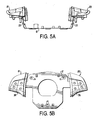
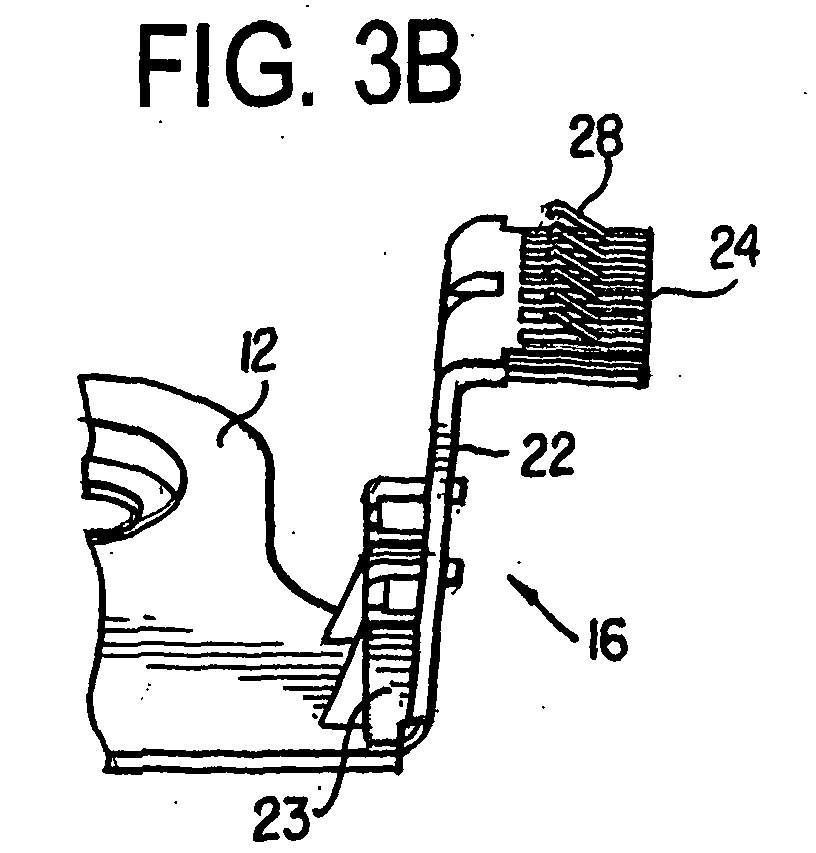
- the primary circuit board 12 is spaced vertically distant, i.e. offset from the button assemblies 18 and 20 (see Fig. 5A). Therefore, the left and right wings 14 and 16 of the primary circuit board 12 include vertically extending arms 22 that rise to engage the button assemblies 18 and 20, as best shown in Figs. 3B and 5A.
- Fig. 3B shows the right wing 16 of the primary circuit board 12, and the description of the arms 22 will be given with respect thereto.
- the arm 22 is formed in a generally L-shape manner so that its top shelf 24 lies substantially parallel to a secondary circuit board 26 of the button assembly 20 (see Fig. 3D).
- the arm 22 is attached to the primary circuit board 12 by way of bracket 23.
- Fig. 3D shows the top shelf 24 having a plurality of spring contacts 28, preferably leaf springs, that extend upward to engage contacts on the bottom surface of the secondary circuit board 26.
- spring contacts 28 are not fixedly secured to the secondary circuit board 26, they can move horizontally relative to the secondary circuit board 26 without disengaging therefrom. Additionally, the spring contacts 28 resiliently engage the second circuit board 26 in the vertical direction so that any vertical movement of the spring contacts 28 are also compensated for without disengaging from the secondary circuit board 26.
- the spring contacts 28 are connected to electrical traces 29 on the primary circuit board 12 through an electrical conductor (not shown) in the arms 22.
- Fig. 3D shows the spring contacts 28 of the right arm 22 engaging the secondary circuit board 26 without a base 30 of the button assembly 20.
- the base 30 of the button assembly 20 is located adjacent the shelf 24 in between the shelf 24 and the secondary circuit board 26, so that the secondary circuit board 26 is placed onto the base 30.
- the base 30 includes one or more openings 32 through which the spring contacts 28 protrude to contact the secondary circuit board 26.
- Fig. 3C shows the right wing 16 having a base 30 without the secondary circuit board 26 thereon, while Fig. 3A shows the left wing 14 with the base 30 and a secondary circuit board 26 attached thereto.
- Fig. 4 shows an exploded view of the multi-function button assemblies 18 and 20.
- the button assemblies comprise a housing 32 having multiple chambers 34 therein for holding buttons 36.
- the buttons 36 operate specific functions in the vehicle, such as controlling the volume of the radio, tuning the radio, increasing or decreasing the cruise control speed, and operation of a mobile phone.
- Each button 36 contains a pin 38 that is inserted into the chamber 34 for engagement with the secondary circuit board 26.
- Underneath the housing is a cover 40 having openings to accommodate the pins 38, the secondary circuit board 26, and the base 30, which are discussed above.
- the primary circuit board 12 can include additional contacts for other features, such as the contacts for the vehicle horns 42 and a clockspring connector 44. Furthermore, it should be understood that additional features may be incorporated into the primary circuit board 12, and that the features provided for by the buttons 36 may be changed or modified without departing from the scope of the invention.
- a driver would press one of the buttons 36 on the steering wheel 10.
- the pin 38 of the button 36 would engage a contact on the secondary circuit board 26, which would send an electrical signal via the spring contacts 28, through an electrical conductor (not shown) in the arm 22 to the electrical traces 29 on the primary circuit board 12.
- the electrical traces 29 connect the left and right button assemblies 18 and 20, and the vehicle horn 42, to the clockpspring connector 44, which acts as the outgoing signal relay point for the primary circuit board 12.
- the signals are transmitted through the clockspring connector 44 to the corresponding electronic component in the vehicle.
- Figs. 5A and 5B show a side and front view of the primary circuit board 12 connected to the left and right button assemblies 18 and 20.
- Fig. 5A shows the vertically extending arms 22 of the primary circuit board 12 that create the necessary depth for placement of an airbag in the steering wheel.
- the contact assembly of the present invention provides a primary circuit board 12 having contact springs 28 which are not firmly fixed to the corresponding contacts of the secondary circuit board 26, so that the primary circuit board 12 is able to move relative to the secondary circuit board 26. Therefore, any minor deviations in the placement of the primary or secondary circuit boards 12 and 26 may be compensated for by movement of one or the other component.
- Fig. 1 shows the steering wheel 10 with left and right button assemblies 18 and 20 located adjacent the center of the steering wheel.
- Small air gaps 50 and 52 exist between the button assemblies 18 and 20 and the airbag cover (not shown) and the steering wheel edge.
- the primary circuit board 12 may be required to move vertically (into the page in Fig. 1) to accommodate the air bag.
Landscapes
- Engineering & Computer Science (AREA)
- Mechanical Engineering (AREA)
- Chemical & Material Sciences (AREA)
- Combustion & Propulsion (AREA)
- Transportation (AREA)
- Physics & Mathematics (AREA)
- Electromagnetism (AREA)
- Air Bags (AREA)
- Steering Controls (AREA)
- Push-Button Switches (AREA)
Abstract
Description
- The present invention is directed to a contact positioning assembly for a steering wheel having a primary circuit board with spring contacts engaging corresponding contacts connected to control buttons on the steering wheel, such that the spring contacts may move relative to the corresponding contacts of the control buttons without disconnecting therefrom.
- Vehicle manufacturers are increasingly incorporating features and functionality into the steering wheel of a car, such as radio volume and tuning control, mobile phone, and cruise control features to allow drivers to operate the various functions of the vehicle without taking their hands off the steering wheel. This provides the driver with the convenience of being able to easily control vehicle functions while decreasing the likelihood of accidents.
- These features have made the steering wheel a control center for various electronic devices located in the vehicle. The increasing number of electrical components, in addition to an air bag, in the relatively small space provided by the steering wheel has increased the precision and tolerances required in manufacturing steering wheels.
- A major disadvantage resulting from the high tolerances is that components not meeting exact specifications will not fit together properly. This is especially problematic for electrical components which must be precisely mated to one another for proper engagement. Typically, electrical components in the steering wheel have been mated using male-female connectors. These connectors operate by inserting a first male contact or plug into a second female contact or receptacle, thereby providing a firm connection between the two contacts.
- However, this type of connection prevents the two contacts from moving relative to one another. If certain steering wheel components are not precisely manufactured, the male-female contacts may not properly align, preventing the proper engagement and mating of the contacts.
- Therefore, it would be advantageous to provide an electrical contact assembly which allows for some movement between a first contact and a second contact, to minimize the manufacturing precision required. It would further be advantageous to provide such an electrical contact assembly to allow and maintain proper electrical contact in case of movement between the first and second contact, and further to, simplify assembly and reduce manufacturing costs.
- The present invention is directed to an electrical contact assembly in a steering wheel having a primary circuit board located in the center of the steering wheel around the steering column. The primary circuit board includes left and right arms which engage and cooperate with left and right button assemblies on the steering wheel to actuate various vehicle controls, such as radio volume and tuning control, in the vehicle. The arms include spring contacts which resiliently and non-fixedly engage a secondary circuit board which is connected to control buttons on the steering wheel. The spring contacts connect the primary circuit board to the secondary circuit board and allow for minor movement between the two without loss of electrical contact. Thus, minor deviation in the positioning of the primary or secondary circuit board may be compensated for without the loss of electrical contact.
-
- FIG. 1 shows an front view of a steering wheel incorporating the present invention;
- FIG. 2 shows a primary circuit board of the present invention;
- FIG. 3A shows the primary circuit board of FIG. 2 with a left arm connected to a secondary circuit board;
- FIG. 3B shows a perspective view of a right arm of the primary circuit board;
- FIG. 3C shows the right arm with the base of a multi-function button assembly attached thereto;
- FIG. 3D shows a perspective view of the right arm engaging the secondary circuit board;
- FIG. 4 shows an exploded view of the multi-function button assembly;
- FIG. 5A shows a side view of the contact position assembly of the present invention; and
- FIG. 5B shows a top view of the contact position assembly of the present invention.
-
- Referring now in detail to the drawings, Fig. 1 shows a front view of a
steering wheel 10 of the present invention, with its center air bag cover removed, and exposing aprimary circuit board 12. Theprimary circuit board 12 includes aleft wing 14 and right wing 16 (see Fig. 2) which extend underneath the left and rightmulti-function button assemblies primary circuit board 12, such that the air bag cover lies flush with thebutton assemblies primary circuit board 12 is provided with apertures 13, which fasten theprimary circuit board 12 to the center of thesteering wheel 10. - Because of the space required by the air bag, the
primary circuit board 12 is spaced vertically distant, i.e. offset from thebutton assemblies 18 and 20 (see Fig. 5A). Therefore, the left andright wings primary circuit board 12 include vertically extendingarms 22 that rise to engage thebutton assemblies - Fig. 3B shows the
right wing 16 of theprimary circuit board 12, and the description of thearms 22 will be given with respect thereto. Thearm 22 is formed in a generally L-shape manner so that itstop shelf 24 lies substantially parallel to asecondary circuit board 26 of the button assembly 20 (see Fig. 3D). Thearm 22 is attached to theprimary circuit board 12 by way ofbracket 23. - Fig. 3D shows the
top shelf 24 having a plurality ofspring contacts 28, preferably leaf springs, that extend upward to engage contacts on the bottom surface of thesecondary circuit board 26. Because thespring contacts 28 are not fixedly secured to thesecondary circuit board 26, they can move horizontally relative to thesecondary circuit board 26 without disengaging therefrom. Additionally, thespring contacts 28 resiliently engage thesecond circuit board 26 in the vertical direction so that any vertical movement of thespring contacts 28 are also compensated for without disengaging from thesecondary circuit board 26. Thespring contacts 28 are connected to electrical traces 29 on theprimary circuit board 12 through an electrical conductor (not shown) in thearms 22. - For purposes of clarity, Fig. 3D shows the
spring contacts 28 of theright arm 22 engaging thesecondary circuit board 26 without abase 30 of thebutton assembly 20. However, thebase 30 of thebutton assembly 20 is located adjacent theshelf 24 in between theshelf 24 and thesecondary circuit board 26, so that thesecondary circuit board 26 is placed onto thebase 30. Thebase 30 includes one ormore openings 32 through which thespring contacts 28 protrude to contact thesecondary circuit board 26. Fig. 3C shows theright wing 16 having abase 30 without thesecondary circuit board 26 thereon, while Fig. 3A shows theleft wing 14 with thebase 30 and asecondary circuit board 26 attached thereto. - Fig. 4 shows an exploded view of the
multi-function button assemblies housing 32 havingmultiple chambers 34 therein forholding buttons 36. Thebuttons 36 operate specific functions in the vehicle, such as controlling the volume of the radio, tuning the radio, increasing or decreasing the cruise control speed, and operation of a mobile phone. Eachbutton 36 contains apin 38 that is inserted into thechamber 34 for engagement with thesecondary circuit board 26. Underneath the housing is a cover 40 having openings to accommodate thepins 38, thesecondary circuit board 26, and thebase 30, which are discussed above. - As shown in Fig. 3, in addition to the functionality provided for by the
buttons 36, theprimary circuit board 12 can include additional contacts for other features, such as the contacts for thevehicle horns 42 and aclockspring connector 44. Furthermore, it should be understood that additional features may be incorporated into theprimary circuit board 12, and that the features provided for by thebuttons 36 may be changed or modified without departing from the scope of the invention. - In operation, a driver would press one of the
buttons 36 on thesteering wheel 10. Thepin 38 of thebutton 36 would engage a contact on thesecondary circuit board 26, which would send an electrical signal via thespring contacts 28, through an electrical conductor (not shown) in thearm 22 to the electrical traces 29 on theprimary circuit board 12. The electrical traces 29 connect the left andright button assemblies vehicle horn 42, to theclockpspring connector 44, which acts as the outgoing signal relay point for theprimary circuit board 12. The signals are transmitted through theclockspring connector 44 to the corresponding electronic component in the vehicle. - Figs. 5A and 5B show a side and front view of the
primary circuit board 12 connected to the left andright button assemblies arms 22 of theprimary circuit board 12 that create the necessary depth for placement of an airbag in the steering wheel. - The contact assembly of the present invention provides a
primary circuit board 12 having contact springs 28 which are not firmly fixed to the corresponding contacts of thesecondary circuit board 26, so that theprimary circuit board 12 is able to move relative to thesecondary circuit board 26. Therefore, any minor deviations in the placement of the primary orsecondary circuit boards - For example, Fig. 1 shows the
steering wheel 10 with left andright button assemblies Small air gaps button assemblies button assemblies steering wheel edge 50 and the airbag cover. Additionally, theprimary circuit board 12 may be required to move vertically (into the page in Fig. 1) to accommodate the air bag. These minor position changes of theprimary circuit board 12 or thebutton assemblies - Although preferred embodiments are specifically illustrated and described herein, it should be appreciated that many modifications and variations of the present invention are possible in light of the above teachings, without departing from the spirit or scope of the invention.
Claims (10)
- A contact assembly for a steering wheel comprising:a first circuit board having at least one vertically extending arm, said arm including a resilient contact thereon for non-fixedly engaging a corresponding contact on a second circuit board, said second circuit board being adapted to cooperate with buttons on the steering wheel to actuate various vehicle functions.
- The contact assembly of claim 1, wherein the vertically extending arm is generally L-shaped with a top shelf lying generally parallel to said second circuit board, the top shelf having the resilient contact thereon for engaging the corresponding contact on said second circuit board.
- The contact assembly of claim 2, wherein the resilient contact is a leaf-spring contact that is pressed into engagement with the corresponding contacts of the second circuit board so as to be able to move both laterally and vertically with respect the second circuit board without disengaging therefrom.
- The contact assembly of claim 1, wherein said second circuit board is located in a base of a multi-function button assembly, the base having an opening so that the resilient contact of the first circuit board may engage the contact of the second circuit board.
- A steering wheel having a primary circuit board located in a first plane and having at least one arm extending out of said first plane, the at least one arm having resilient contacts on an end thereof;
a button assembly for controlling various vehicle functions, the button assembly having a secondary circuit board which is connected to the resilient contacts on the at least one arm of the primary circuit board, such that the secondary circuit board lies in a second plane that is offset from the first plane. - The steering wheel of claim 5, wherein the at least one arm is generally L-shaped and has a shelf lying adjacent to the second circuit board, and the resilient contacts are located on the shelf.
- The steering wheel of claim 5, wherein the resilient contacts are leaf-springs that non-fixedly engage the contacts of the second circuit board so that they can move parallel or perpendicular to the second plane without disengaging from the contacts of the second circuit board.
- The steering wheel of claim 5, wherein the button assembly includes a housing having at least one cavity therein, the at least one cavity holding at least one button which controls a vehicle function, the at least one button having a pin extending through the cavity for engaging the second circuit board.
- The steering wheel of claim 8, wherein the button assembly includes a base that lies between the at least one arm and the secondary circuit board, the base having an opening to allow the resilient contacts to protrude therethrough to engage the contacts of the secondary circuit board.
- The steering wheel of claim 5, wherein the primary circuit board is located in the center of the steering wheel and includes two wings extending in generally opposite directions therefrom, the wings each having the at least one arm for engaging the secondary circuit board, and two button assemblies located on opposite sides of the center of the steering wheel for cooperating with each arm of the primary circuit board.
Applications Claiming Priority (2)
| Application Number | Priority Date | Filing Date | Title |
|---|---|---|---|
| US713049 | 2003-11-17 | ||
| US10/713,049 US7029284B2 (en) | 2003-11-17 | 2003-11-17 | Floating contact assembly for a steering wheel |
Publications (2)
| Publication Number | Publication Date |
|---|---|
| EP1538029A1 true EP1538029A1 (en) | 2005-06-08 |
| EP1538029B1 EP1538029B1 (en) | 2006-12-13 |
Family
ID=34465646
Family Applications (1)
| Application Number | Title | Priority Date | Filing Date |
|---|---|---|---|
| EP04257065A Expired - Lifetime EP1538029B1 (en) | 2003-11-17 | 2004-11-15 | Floating contact assembly for a steering wheel |
Country Status (3)
| Country | Link |
|---|---|
| US (1) | US7029284B2 (en) |
| EP (1) | EP1538029B1 (en) |
| DE (1) | DE602004003666T2 (en) |
Cited By (2)
| Publication number | Priority date | Publication date | Assignee | Title |
|---|---|---|---|---|
| WO2007020019A1 (en) * | 2005-08-12 | 2007-02-22 | Leopold Kostal Gmbh & Co. Kg | Steering column module |
| WO2017093313A1 (en) * | 2015-12-02 | 2017-06-08 | Trw Automotive Safety Systems Gmbh | Cable conduit device for connection cables of an airbag module, wiring system, airbag module, and steering wheel or vehicle comprising a cable conduit device of said type |
Families Citing this family (11)
| Publication number | Priority date | Publication date | Assignee | Title |
|---|---|---|---|---|
| JP4415689B2 (en) * | 2004-02-04 | 2010-02-17 | パナソニック株式会社 | Steering |
| US20050284689A1 (en) * | 2004-06-23 | 2005-12-29 | Michael Simpson | Clockspring with sound dampener |
| US20060162485A1 (en) * | 2005-01-07 | 2006-07-27 | Jeremy Leng | Automotive steering wheel |
| US9308930B2 (en) * | 2012-04-06 | 2016-04-12 | Autoliv Asp, Inc. | Steering wheel with switch assembly |
| CN103318245A (en) * | 2013-06-04 | 2013-09-25 | 无锡伊佩克科技有限公司 | Multifunctional steering wheel |
| US11034374B2 (en) * | 2017-08-10 | 2021-06-15 | Toyoda Gosei Co., Ltd. | Steering wheel |
| WO2019181049A1 (en) * | 2018-03-22 | 2019-09-26 | アルプスアルパイン株式会社 | Rotary connector |
| DE112019002171B4 (en) | 2018-05-30 | 2022-10-20 | Joyson Safety Systems Acquisition Llc | Integrated electronic control unit for a steering wheel assembly |
| CN115675611A (en) * | 2021-07-29 | 2023-02-03 | 延锋汽车智能安全系统有限责任公司 | Steering wheel components and steering wheel assemblies |
| CN216943243U (en) * | 2021-12-29 | 2022-07-12 | 奥托立夫开发公司 | Steering wheel |
| DE102023203774A1 (en) * | 2023-04-25 | 2024-10-31 | Joyson Safety Systems Acquisition Llc | METHOD FOR ESTABLISHING AN ELECTRICAL CONNECTION IN THE PRODUCTION OF A VEHICLE STEERING WHEEL |
Citations (5)
| Publication number | Priority date | Publication date | Assignee | Title |
|---|---|---|---|---|
| JPH0295949A (en) * | 1988-09-30 | 1990-04-06 | Omron Tateisi Electron Co | Steering switch module |
| US5331124A (en) * | 1992-07-20 | 1994-07-19 | Methode Electronics, Inc. | Wireless floating horn switch |
| JPH10338146A (en) * | 1997-06-09 | 1998-12-22 | Toyoda Gosei Co Ltd | Switch structure for steering wheel |
| US6150621A (en) * | 1997-11-21 | 2000-11-21 | Yazaki Corporation | Steering switch module |
| EP1091376A2 (en) * | 1999-10-09 | 2001-04-11 | Eaton Corporation | Electric switch with pivoting knob |
Family Cites Families (10)
| Publication number | Priority date | Publication date | Assignee | Title |
|---|---|---|---|---|
| DE1904622C3 (en) * | 1968-02-10 | 1974-08-15 | Nagoya Rupat.-Anwaelte, 8000 Muenchen | Electrical connection arrangement for control switches built into the steering wheel of a motor vehicle |
| US4616224A (en) * | 1983-03-16 | 1986-10-07 | Sheller-Globe Corporation | Multifunction steering wheel |
| US4638131A (en) * | 1986-01-15 | 1987-01-20 | General Motors Corporation | Steering wheel pad keyboard switch assembly |
| US5895115A (en) * | 1996-01-16 | 1999-04-20 | Lumitex, Inc. | Light emitting panel assemblies for use in automotive applications and the like |
| US5952633A (en) * | 1996-12-20 | 1999-09-14 | Eaton Corporation | Steering column stalk switch for use with multiplexed electronic switching |
| JPH10228844A (en) * | 1997-02-14 | 1998-08-25 | Niles Parts Co Ltd | Combination switch structure for vehicle |
| DE19819695C2 (en) * | 1998-05-02 | 2000-12-07 | Eaton Controls Gmbh | Steering wheel switch for a motor vehicle |
| US6403899B1 (en) * | 2000-03-23 | 2002-06-11 | Valeo Electrical Systems, Inc. | Vehicle fog lamp interlock switch apparatus |
| US6733300B2 (en) * | 2001-07-05 | 2004-05-11 | Alps Electric Co., Ltd. | Rotary connector equipped with versatile lead block |
| US6907328B2 (en) * | 2003-06-10 | 2005-06-14 | Motorola, Inc. | Switch apparatus for a driver information interface |
-
2003
- 2003-11-17 US US10/713,049 patent/US7029284B2/en not_active Expired - Fee Related
-
2004
- 2004-11-15 DE DE602004003666T patent/DE602004003666T2/en not_active Expired - Lifetime
- 2004-11-15 EP EP04257065A patent/EP1538029B1/en not_active Expired - Lifetime
Patent Citations (5)
| Publication number | Priority date | Publication date | Assignee | Title |
|---|---|---|---|---|
| JPH0295949A (en) * | 1988-09-30 | 1990-04-06 | Omron Tateisi Electron Co | Steering switch module |
| US5331124A (en) * | 1992-07-20 | 1994-07-19 | Methode Electronics, Inc. | Wireless floating horn switch |
| JPH10338146A (en) * | 1997-06-09 | 1998-12-22 | Toyoda Gosei Co Ltd | Switch structure for steering wheel |
| US6150621A (en) * | 1997-11-21 | 2000-11-21 | Yazaki Corporation | Steering switch module |
| EP1091376A2 (en) * | 1999-10-09 | 2001-04-11 | Eaton Corporation | Electric switch with pivoting knob |
Non-Patent Citations (2)
| Title |
|---|
| PATENT ABSTRACTS OF JAPAN vol. 014, no. 300 (M - 0991) 28 June 1990 (1990-06-28) * |
| PATENT ABSTRACTS OF JAPAN vol. 1999, no. 03 31 March 1999 (1999-03-31) * |
Cited By (5)
| Publication number | Priority date | Publication date | Assignee | Title |
|---|---|---|---|---|
| WO2007020019A1 (en) * | 2005-08-12 | 2007-02-22 | Leopold Kostal Gmbh & Co. Kg | Steering column module |
| JP2009504475A (en) * | 2005-08-12 | 2009-02-05 | レオポルト・コスタール・ゲゼルシヤフト・ミト・ベシユレンクテル・ハフツング・ウント・コンパニー・コマンデイトゲゼルシヤフト | Steering column module |
| US7595457B2 (en) | 2005-08-12 | 2009-09-29 | Leopold Kostal Gmbh & Co. Kg | Steering column module |
| CN101233017B (en) * | 2005-08-12 | 2010-12-15 | 利奥波德·科世达责任有限股份公司 | Steering column module |
| WO2017093313A1 (en) * | 2015-12-02 | 2017-06-08 | Trw Automotive Safety Systems Gmbh | Cable conduit device for connection cables of an airbag module, wiring system, airbag module, and steering wheel or vehicle comprising a cable conduit device of said type |
Also Published As
| Publication number | Publication date |
|---|---|
| DE602004003666T2 (en) | 2007-10-25 |
| EP1538029B1 (en) | 2006-12-13 |
| US7029284B2 (en) | 2006-04-18 |
| US20050106913A1 (en) | 2005-05-19 |
| DE602004003666D1 (en) | 2007-01-25 |
Similar Documents
| Publication | Publication Date | Title |
|---|---|---|
| US7029284B2 (en) | Floating contact assembly for a steering wheel | |
| JP6123004B1 (en) | connector | |
| JP2021093446A (en) | Electronic device | |
| JP2010083210A (en) | Light source unit for vehicle interior | |
| EP1988608A1 (en) | Connector | |
| JP2019192861A (en) | Housing structure of printed circuit board with connector | |
| JP2006269632A (en) | Electric circuit board storage box | |
| TW201917956A (en) | Connector | |
| EP1340294B1 (en) | Microelectronic connector with open-cavity insert | |
| JP2010003413A (en) | Coaxial connector with switch | |
| EP3118876B1 (en) | Switch apparatus having wireless function | |
| CN109994849A (en) | Connector construction | |
| JP2005050694A (en) | connector | |
| US6190194B1 (en) | Attachment and connection structure of electrical equipment unit | |
| JP2008108560A (en) | connector | |
| US7563138B2 (en) | Electrical card connector with improved contacts | |
| US7125280B1 (en) | Electrical connector assembly | |
| US20150244091A1 (en) | Connector and connector assembly | |
| JP2004273199A (en) | Switch device and method of manufacturing the same | |
| JP2014060130A (en) | Shield connector for board | |
| JP2003036921A (en) | Connector with shutter | |
| KR101897076B1 (en) | Elctronic control device having connector coupling structure | |
| KR102019379B1 (en) | Integrated type electronic control device | |
| KR200439215Y1 (en) | Slide switch module | |
| KR102499801B1 (en) | Variable connector and electronic control device including the same |
Legal Events
| Date | Code | Title | Description |
|---|---|---|---|
| PUAI | Public reference made under article 153(3) epc to a published international application that has entered the european phase |
Free format text: ORIGINAL CODE: 0009012 |
|
| AK | Designated contracting states |
Kind code of ref document: A1 Designated state(s): AT BE BG CH CY CZ DE DK EE ES FI FR GB GR HU IE IS IT LI LU MC NL PL PT RO SE SI SK TR |
|
| AX | Request for extension of the european patent |
Extension state: AL HR LT LV MK YU |
|
| 17P | Request for examination filed |
Effective date: 20051208 |
|
| AKX | Designation fees paid |
Designated state(s): DE FR GB |
|
| GRAP | Despatch of communication of intention to grant a patent |
Free format text: ORIGINAL CODE: EPIDOSNIGR1 |
|
| GRAS | Grant fee paid |
Free format text: ORIGINAL CODE: EPIDOSNIGR3 |
|
| GRAA | (expected) grant |
Free format text: ORIGINAL CODE: 0009210 |
|
| AK | Designated contracting states |
Kind code of ref document: B1 Designated state(s): DE FR GB |
|
| REG | Reference to a national code |
Ref country code: GB Ref legal event code: FG4D |
|
| REF | Corresponds to: |
Ref document number: 602004003666 Country of ref document: DE Date of ref document: 20070125 Kind code of ref document: P |
|
| ET | Fr: translation filed | ||
| PLBE | No opposition filed within time limit |
Free format text: ORIGINAL CODE: 0009261 |
|
| STAA | Information on the status of an ep patent application or granted ep patent |
Free format text: STATUS: NO OPPOSITION FILED WITHIN TIME LIMIT |
|
| 26N | No opposition filed |
Effective date: 20070914 |
|
| REG | Reference to a national code |
Ref country code: FR Ref legal event code: PLFP Year of fee payment: 12 |
|
| REG | Reference to a national code |
Ref country code: FR Ref legal event code: PLFP Year of fee payment: 13 |
|
| REG | Reference to a national code |
Ref country code: FR Ref legal event code: PLFP Year of fee payment: 14 |
|
| REG | Reference to a national code |
Ref country code: FR Ref legal event code: PLFP Year of fee payment: 15 |
|
| PGFP | Annual fee paid to national office [announced via postgrant information from national office to epo] |
Ref country code: GB Payment date: 20181114 Year of fee payment: 15 |
|
| PGFP | Annual fee paid to national office [announced via postgrant information from national office to epo] |
Ref country code: DE Payment date: 20191105 Year of fee payment: 16 |
|
| PGFP | Annual fee paid to national office [announced via postgrant information from national office to epo] |
Ref country code: FR Payment date: 20191014 Year of fee payment: 16 |
|
| GBPC | Gb: european patent ceased through non-payment of renewal fee |
Effective date: 20191115 |
|
| PG25 | Lapsed in a contracting state [announced via postgrant information from national office to epo] |
Ref country code: GB Free format text: LAPSE BECAUSE OF NON-PAYMENT OF DUE FEES Effective date: 20191115 |
|
| REG | Reference to a national code |
Ref country code: DE Ref legal event code: R119 Ref document number: 602004003666 Country of ref document: DE |
|
| PG25 | Lapsed in a contracting state [announced via postgrant information from national office to epo] |
Ref country code: FR Free format text: LAPSE BECAUSE OF NON-PAYMENT OF DUE FEES Effective date: 20201130 |
|
| PG25 | Lapsed in a contracting state [announced via postgrant information from national office to epo] |
Ref country code: DE Free format text: LAPSE BECAUSE OF NON-PAYMENT OF DUE FEES Effective date: 20210601 |