EP1537801A1 - Stop section for slide fastener, and slide fastener having such stop section - Google Patents
Stop section for slide fastener, and slide fastener having such stop section Download PDFInfo
- Publication number
- EP1537801A1 EP1537801A1 EP03736071A EP03736071A EP1537801A1 EP 1537801 A1 EP1537801 A1 EP 1537801A1 EP 03736071 A EP03736071 A EP 03736071A EP 03736071 A EP03736071 A EP 03736071A EP 1537801 A1 EP1537801 A1 EP 1537801A1
- Authority
- EP
- European Patent Office
- Prior art keywords
- fastener
- end stop
- synthetic resin
- slide fastener
- fused
- Prior art date
- Legal status (The legal status is an assumption and is not a legal conclusion. Google has not performed a legal analysis and makes no representation as to the accuracy of the status listed.)
- Granted
Links
Images







Classifications
-
- A—HUMAN NECESSITIES
- A44—HABERDASHERY; JEWELLERY
- A44B—BUTTONS, PINS, BUCKLES, SLIDE FASTENERS, OR THE LIKE
- A44B19/00—Slide fasteners
- A44B19/24—Details
- A44B19/36—Means for permanently uniting the stringers at the end; Means for stopping movement of slider at the end
-
- A—HUMAN NECESSITIES
- A44—HABERDASHERY; JEWELLERY
- A44B—BUTTONS, PINS, BUCKLES, SLIDE FASTENERS, OR THE LIKE
- A44B19/00—Slide fasteners
- A44B19/42—Making by processes not fully provided for in one other class, e.g. B21D53/50, B21F45/18, B22D17/16, B29D5/00
- A44B19/60—Applying end stops upon stringer tapes
-
- Y—GENERAL TAGGING OF NEW TECHNOLOGICAL DEVELOPMENTS; GENERAL TAGGING OF CROSS-SECTIONAL TECHNOLOGIES SPANNING OVER SEVERAL SECTIONS OF THE IPC; TECHNICAL SUBJECTS COVERED BY FORMER USPC CROSS-REFERENCE ART COLLECTIONS [XRACs] AND DIGESTS
- Y10—TECHNICAL SUBJECTS COVERED BY FORMER USPC
- Y10T—TECHNICAL SUBJECTS COVERED BY FORMER US CLASSIFICATION
- Y10T24/00—Buckles, buttons, clasps, etc.
- Y10T24/25—Zipper or required component thereof
- Y10T24/2598—Zipper or required component thereof including means for obstructing movement of slider
Definitions
- the present invention relates to end stops, i.e., a top end stop or a bottom end stop for a slide fastener and a hidden slide fastener in which coil-type or zigzag-type linear fastener elements of synthetic resin are mounted on a side edge of a fastener tape and relates to a slide fastener having the same end stops.
- a top end stop and a bottom end stop of a coil-type or zigzag-type linear slide fastener and hidden slide fastener made of synthetic resin According to a stop end 22 disclosed in Japanese Utility Model Application Publication No. 56-51773, a synthetic resin piece 21 having a circular section is formed on a tape-side rear face of heads 10 of plural elements at a terminal end of a linear fastener element row 3 such that it is capable of being fused, as shown in FIG. 26, and an end portion of the synthetic resin piece 21 located at the terminal end of the element row 3 is bent to a surface so as to produce a bent portion 21a.
- the end face of the bent portion 21a is formed lower than a surface of the elements and then, the bent portion 21a is fused with a coupling face formed in a dented state in a side face of a head 10 of an element at a terminal end of the element row.
- a film piece 25 made of synthetic resin is placed on and fused with a top side of plural elements of an liner fastener element row 3 made of synthetic resin, and a film piece 25 above a sewing yarn 24 which sews leg portions 11 of the elements is formed thicker than an other portion so as to provide a convex row 25a and then, the sewing yarn 24 is protected by this convex row 25a while the other portion of the film piece 25 except for the convex row 25a adheres up to a rear face of the elements so as to embrace it.
- a metallic pin 28 with a head is inserted into a gap portion 27 existing at a rear side of plural element heads 10 in conditions in which coil type or zigzag type linear fastener element rows 3 made of synthetic resin are coupled with each other, thereby fixing right and left elements.
- the synthetic resin piece 21 is fused with a bottom face of the heads 10 of the linear fastener element row 3 with ultrasonic welding under a pressure and an end of the synthetic resin piece is bent to a surface side of the elements and fused with the side face of the head 10 of the element. For the reason, the welding processing of the synthetic resin 21 is extremely troublesome, so that the end stop cannot be produced at a cheap price. Because the synthetic resin piece 21 is fused with the surface of the element, it may peel off during usage.
- a first basic configuration of the present invention is an end stop for a slide fastener which is formed by fusing a synthetic resin piece attached over plural fastener elements located at a terminal end side of a synthetic resin made linear fastener element row mounted on a side edge of an ordinary type or hidden type slide fastener tape.
- the synthetic resin made linear fastener element row is mounted on the side edge of the fastener tape and then a synthetic resin piece is attached over plural fastener elements located at a terminal end of the fastener element row and fused so as to form the end stop for a slider.
- the synthetic resin piece a rod-like body or a curved sheet-like body may be used.
- a rod-like body or a curved sheet-like body By using such a rod-like body or a curved sheet-like body, the synthetic resin piece can be attached easily and accurately, and moreover, the synthetic resin piece can be produced easily.
- the rod-like body is inserted into a coupling space portion located in a rear side of coupling heads in the linear fastener elements and fused therein, generation of burrs on the surface of the linear fastener elements is suppressed, in addition to the above-described effects, so that an excellent quality end stop can be formed.
- the rod-like body is crushed and fused together with the coupling heads of the linear fastener elements from the front and rear surfaces. According to such fusing, the end stop, which stops the slider securely at a terminal end of the linear fastener element row and prevents the slider from slipping out, can be formed.
- the sheet-like body is fused together to cover the coupling heads, leg portions and connecting portions of the linear fastener elements. According to such measure, generation of burrs on the surface of the linear fastener elements can be prevented and an excellent quality end stop can be formed.
- the rod-like body is disposed inside the linear fastener element row, the linear fastener element row being in a non-engaged state, and fused so as to form a top end stop.
- the rod-like body can be inserted into the inside of the linear fastener element row easily in a fastener stringer in which its fastener elements are not coupled, so as to form the top end stop easily.
- the sheet-like body is disposed on the surface of the linear fastener element row, the linear fastener element row being in a non-coupled state, and fused together so as to form a top end stop.
- the sheet-like body can be easily applied to a fastener stringer in which its fastener elements are not coupled, so as to form a top end stop easily.
- the rod-like body is disposed inside each of the linear fastener element rows in a coupled state and fused together so as to form a bottom stop end. Consequently, the rod-like body can be applied to a fastener chain easily, in which its fastener elements are coupled, so as to form a bottom end stop easily.
- the bottom end stop can be formed by using the sheet-like body also. That is, the sheet-like body is disposed on the surface of each of the linear fastener element rows in a coupled state and fused together so as to form a bottom end stop. Consequently, the sheet-like body can be easily applied to a fastener chain, in which fastener elements are coupled, so as to form a bottom end stop easily.
- a second basic configuration of the present invention is a slider fastener having the above-described end stop and which is characterized in that the fastener tape in a fastener chain undergoes special treatment, that is, patterning by ink jet and/or waterproof processing.
- special treatment that is, patterning by ink jet and/or waterproof processing.
- a mono-filament of synthetic resin such as polyamide or polyester is wound into a coil-like shape or bent into a zigzag form so as to produce a linear fastener element row 3.
- This linear fastener element row 3 is sewed on a side edge of a fastener tape with a sewing yarn 8 or mounted by weaving or knitting in the fastener tape, so as to finish an ordinary type slide fastener or a hidden type slide fastener.
- the coil-like or zigzag-like linear fastener elements 3 are respectively comprised of a coupling head 10, upper and lower leg portions 11, a connecting portion 12 and a coupling space portion 13.
- a core thread 9 is placed through the inside of the linear fastener element row 3, so that it is intended to mount the fastener element row 3 onto a fastener tape 4 or stabilize the engagement operation of the fastener elements 3.
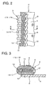
- the present invention concerns an end stop 14, i.e., a top end stop 15 and a bottom end stop 16, which is applicable to both an ordinary type slide fastener and a hidden type slide fastener formed in the above-described manner. If the end stop 14 for the top end stop 15 in the ordinary type slide fastener shown in FIGS. 1 to 3 will be described, an element in which the core thread 9 is passed through the coil-like linear fastener element row 3 is sewed on the side edge of the fastener tape 4 such that the coupling head 10 is projected from the side edge so as to produce a fastener stringer 2.
- a synthetic resin piece 5 which is formed of the same kind of thermoplastic resin such as polyamide or polyester as the fastener element 3 or resin having a low melting point into a round rod-like body 6, is passed through the coupling space portion 13 formed in the rear side of the coupling heads 10 of plural fastener elements 3 existing at a terminal end of the fastener stringer 2, and the rod-like body 6 is held within the coupling space portion 13 surrounded by the fastener elements 3 and the core thread 9 and added thereto.
- thermoplastic resin such as polyamide or polyester as the fastener element 3 or resin having a low melting point into a round rod-like body 6
- the rod-like body 6 added to the coupling space portion 13 is fused with the fastener element 3 and the core thread 9 by ultrasonic welding. Therefore, the coupling space portion 13 existing in the rear side of the coupling heads 10 of the fastener elements 3 is closed by the fused synthetic resin piece 5, so that the coupling heads 10 of mating fastener elements 3 are blocked from invading into the coupling space portion 13 for engagement. As a result, it exerts a stop function of the end stop as the top end stop 15 for preventing a slider from slipping out of the fastener chain 1.
- the rod-like body 6 of the synthetic resin piece 5 is fused within the coil-like fastener elements 3, no burr is generated on the surface of the fastener elements 3, so that a good-quality top end stop 15 is finished.
- the size and shape of the rod-like body 6 for use is selected appropriately depending on the size of the applied fastener elements 3 and the shape of the coupling space portion 13.
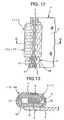
- the end stop 14 shown in FIGS. 4 to 6 is a top end stop 15 for a hidden type slide fastener.
- the element in which the core thread 9 is placed through the coil-like linear fastener element row 3 is sewed onto the fastener tape 4 through the leg portions 11 such that the connecting portions 12 of the fastener elements 3 are located on a side edge of the fastener tape 4.
- the fastener tape 4 is folded back near the sewing yarn 8 existing inside the fastener tape 4 so as to form a state in which the coupling heads 10 project from a folded-back portion 17. Consequently, the hidden type fastener stringer 2 is completed.
- the rod-like body 6 of the synthetic resin piece 5 is inserted into the coupling space portion 13 existing in the rear side of the coupling heads 10 of plural fastener elements 3 existing at the terminal end of the fastener stringer 2 and attached thereto.
- the rod-like body 6 attached to the coupling space portion 13 is fused to the fastener elements 3 and the core thread 9 by ultrasonic welding.
- the coupling space portion 13 existing in the rear side of the coupling head 10 is closed by the synthetic resin piece 5 like the ordinary type fastener element row 3, so that the coupling heads 10 of the mating fastener elements 3 are blocked from their engagement.
- the top end stop 15 is located in the rear side also. If there is burr on the top end stop 15, it may often make a direct contact with the skin of the neck or the like and hence, it is necessary to block generation of such burr completely. As for this point in the top end stop 15 of the invention, because the rod-like body 6 as the synthetic resin piece 5 is passed through the inside of the fastener element row 3 and fused therein, no burr is generated on the surface of the fastener element row 3 and as a result, a good-quality hidden slide fastener can be finished. Further, because the external shape of the end stop 14 does not change, when the hidden type slide fastener is sewed on clothes, there never occurs such an inconvenience that the end stop 14 may make contact with a sewing machine foot guide.
- the round rod-like body 6 formed of the synthetic resin piece 5 is inserted through the coupling space portion 13 existing in the rear side of the coupling heads 10 of plural fastener elements 3 at the terminal end of the fastener chain 1, and held and attached thereto. After attached to the coupling space portion 13, the rod-like body 6 is fused with and fixed to the fastener elements 3 and the core thread 9 by ultrasonic welding, so that the end stop 14 as the bottom end stop 16 for the ordinary type slide fastener is completed.
- the rod-like body 6 as the synthetic resin piece 5 is inserted into the coupling space portion 13 existing in the rear side of the coupling heads 10 of plural fastener elements 3 at the terminal end of the fastener chain 1, and held in and attached to the coupling space portion 13. Thereafter, the rod-like body 6 is fused with the fastener elements 3 and the core thread 9 by ultrasonic welding and fixed thereto, so as to complete the end stop 14 as the bottom end stop 16 for the hidden type slide fastener.
- the rod-like body 6 of the synthetic resin piece 5 which is inserted into the coupling space portion 13 existing in the rear side of the coupling heads 10 of the fastener element row 3 mounted on the folded-back portion 17 of the fastener tape 4 in the fastener stringer 2 and held in and attached to the coupling space portion 13, is fused with the fastener element row 3 and the core thread 9 by ultrasonic welding.
- the coupling heads 10 of the fastener element row 3 are pressed from top and bottom, that is, form the front and rear surfaces so as to crush and fix the rod-like body 6 to form the top end stop 15.
- the stop function of the slider is established clearly.
- the end stop 14 of this type can be applied to the bottom end stop 16 of the fastener chain 1 and can be applied to the ordinary type slide fastener also.
- the rod-like body 6 is employed as the synthetic resin piece 5 which is a base material constituting the end stop 14, as the synthetic resin piece 5 used for the end stops 14 for the slide fasteners of the respective embodiments which will be described below, a synthetic resin piece 5 which is formed into the curved sheet-like body 7 is used, the sheet-like body 7 being made by such matter that a tube molded from thermoplastic resin such as polyamide or polyester, or resin having a low melting point is cut out along its one side and opened up.
- an element, in which the core thread 9 is passed through the coil-like fastener element row 3, is sewed on the side edge of the fastener tape 4 such that the coupling heads 10 project from the side edge so as to produce the fastener stringer 2.
- an element in which the core thread 9 is passed through the coil-like linear fastener element row 3 is sewed to the fastener tape 4 through the leg portions 11 such that the connecting portions 12 of the fastener elements 3 are located on the side edge of the fastener tape 4 and then, the fastener tape 4 is folded back near the sewing yarn 8 existing inside the fastener tape 4 such that the coupling heads 10 project from the folded-back portion 17 so as to produce the hidden type fastener stringer 2.
- the appearing coupling head 10, the leg portions 11 and the connecting portions 12 in the plural fastener elements 3 existing at the terminal end of the fastener stringer 2 are surrounded and covered with the curved synthetic resin piece 5.
- the synthetic resin piece 5 is fused with the fastener element row 3 by ultrasonic welding and fixed thereto so as to block the coupling heads 10 of the mating fastener elements 3 from invading into the coupling space portion 13 for their engagement, thereby forming the top end stop 15 which prevents the slider from slipping out.
- the synthetic resin piece 5 is made to contact with the guide post of the slider and the top end stop which prevents the slider from slipping out.
- the end stops 14 as the top end stop 15 and bottom end stop 16 of a rigid ordinary type slide fastener and hidden type slide fastener may be formed by inserting the rod-like body 6 of the synthetic resin piece 5 into the coupling space portion 13 of the linear fastener element row 3 and attaching the rod-like body 6 to the coupling space portion 13 and by covering the surface of the linear fastener element row 3 with the sheet-like body 7 of the synthetic resin piece 5 and then attaching the synthetic resin piece to the linear fastener element row 3, that is, it is possible to use the rod-like body 6 and the sheet-like body 7 at the same time and fuse the rod-like body 6 and the sheet-like body 7 with the linear fastener element row 3 by ultrasonic welding.
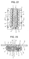
- the slide fastener shown here is an ordinary type slide fastener and various kinds of patterns, characters and the like are represented on the fastener tapes 4 located at the surface side A of the fastener chain 1 by ink jet as a special processing or waterproof processing is performed to the fastener tapes 4.
- the core thread 9 is attached to the synthetic resin coil-like or zigzag-like linear fastener element row 3, and the linear fastener element row 3 is sewed with the sewing yarn 8 on the fastener tape 4 located at the rear surface side B of the fastener chain 1 and attached to the edge portion of the tape so as to complete the fastener chain 1.
- the rod-like body 6 as the synthetic resin piece 5 is inserted into the coupling space portion 13 existing in the rear side of the coupling heads 10 of the plural fastener elements 3 on both sides located at the terminal end side of coupled fastener element rows 3 disposed on the rear surface side B and the rod-like body 6 is attached thereto.
- the rod-like body 6 is fused by ultrasonic welding and fixed to the coupling space portion 13 so as to produce the end stop 14 as the bottom end stop 16.
- This type of the end stop 14 is also applicable for the top end stop 15 at the upper terminal end of the fastener stringer 2.
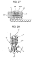
- the coupling heads 10, the leg portions 11 and the connecting portions 12, which appear on the fastener tape 4, of the plural fastener elements 3 existing at the terminal end of coupled fastener element rows 3 disposed on the rear surface side B of the fastener chain 1 are surrounded with the curved sheet-like body 7 of the synthetic resin piece 5 and the curved sheet-like body 7 is attached thereto with covering them.
- this sheet-like body 7 is fused with and fixed on the fastener element row 3 by ultrasonic welding so as to produce the end stop 14 as the bottom end stop 16.
- This type of the end stop 14 is also applicable to the top end stop 15 at the upper terminal end of the fastener stringer 2.
- the fastener chain 1 having the above-described end stop 14 can be finished as a fastener chain 1 having a very excellent appearance because no trace indicating an existence of the end stop 14 appears on the fastener tapes 4 on the surface side A. Meanwhile, the fastener chain 1 which undergoes the special treatment at its fastener tapes 4 is applicable to the hidden type fastener chain 1 as well as the ordinary type, and as a result, an excellent appearance hidden type slide fastener can be completed.
Landscapes
- Slide Fasteners (AREA)
- Lining Or Joining Of Plastics Or The Like (AREA)
Abstract
Description
Claims (11)
- An end stop for a slide fastener, characterized in that the end stop is formed by fusing a synthetic resin piece 5 attached to plural fastener elements 3 located at a terminal end of a linear fastener element row 3 of synthetic resin, the linear fastener element row mounted on a side edge of a fastener tape 4.
- The end stop for the slide fastener according to claim 1, wherein the synthetic resin piece 5 is composed of a rod-like body 6.
- The end stop for the slide fastener according to claim 1, wherein the synthetic resin 5 is composed of a curved sheet-like body 7.
- The end stop for the slide fastener according to claim 2, wherein the rod-like body 6 is inserted into a coupling space portion 13 located in a rear side of coupling heads 10 in a linear fastener element row 3 and fused.
- The end stop for the slide fastener according to claim 4, wherein the rod-like body 6 is crushed from front and rear surfaces together with the coupling heads 10 in the linear fastener element row 3 and fused.
- The end stop for the slide fastener according to claim 3, wherein the sheet-like body 7 covers surfaces of coupling heads 10, leg portions 11 and connecting portions 12 in the linear fastener element row 3 and is fused.
- The end stop for the slide fastener according to any one of claims 1, 2 and 4, wherein the rod-like body 6 is disposed inside linear fastener element rows 3 in a non-coupled state and fused so as to form a top end stop 15.
- The end stop for the slide fastener according to any one of claims 1, 3 and 6, wherein the sheet-like body 7 is disposed on surfaces of linear fastener element rows 3 in a non-engaged state and fused so as to form a top end stop 15.
- The end stop for the slide fastener according to any one of claims 1, 2 and 4, wherein the rod-like body 6 is disposed inside linear fastener element rows 3 in a coupled state and fused so as to form a bottom end stop 16.
- The end stop for the slide fastener according to any one of claims 1, 3 and 6, wherein the sheet-like body 7 is disposed on surfaces of the linear fastener element rows 3 in a coupled state and fused so as to form a bottom end stop 16.
- A slide fastener, characterized in that a pattern 20 formed by ink jet is represented and/on or waterproof processing is performed in a fastener tape 4 on a surface side A of a fastener chain 1 having an end stop formed by welding a synthetic resin piece 5 attached over plural fastener elements 3 located at a terminal end of a linear fastener element row 3 of synthetic resin mounted on a side edge of the fastener tape 4.
Applications Claiming Priority (3)
| Application Number | Priority Date | Filing Date | Title |
|---|---|---|---|
| JP2002179532A JP4116827B2 (en) | 2002-06-20 | 2002-06-20 | Slide fastener stop |
| JP2002179532 | 2002-06-20 | ||
| PCT/JP2003/007188 WO2004000062A1 (en) | 2002-06-20 | 2003-06-06 | Stop section for slide fastener, and slide fastener having such stop section |
Publications (3)
| Publication Number | Publication Date |
|---|---|
| EP1537801A1 true EP1537801A1 (en) | 2005-06-08 |
| EP1537801A4 EP1537801A4 (en) | 2006-11-29 |
| EP1537801B1 EP1537801B1 (en) | 2012-09-19 |
Family
ID=29996569
Family Applications (1)
| Application Number | Title | Priority Date | Filing Date |
|---|---|---|---|
| EP03736071A Expired - Lifetime EP1537801B1 (en) | 2002-06-20 | 2003-06-06 | Method of making a slide fastener |
Country Status (12)
| Country | Link |
|---|---|
| US (1) | US7231697B2 (en) |
| EP (1) | EP1537801B1 (en) |
| JP (1) | JP4116827B2 (en) |
| KR (1) | KR100571971B1 (en) |
| CN (1) | CN100479691C (en) |
| AU (1) | AU2003242240A1 (en) |
| BR (1) | BR0312184B1 (en) |
| ES (1) | ES2392165T3 (en) |
| MX (1) | MXPA04012609A (en) |
| PL (1) | PL375145A1 (en) |
| TW (1) | TWI237554B (en) |
| WO (1) | WO2004000062A1 (en) |
Cited By (1)
| Publication number | Priority date | Publication date | Assignee | Title |
|---|---|---|---|---|
| EP1543739A3 (en) * | 2003-12-19 | 2006-05-17 | Ykk Corporation | End stop for slide fastener |
Families Citing this family (18)
| Publication number | Priority date | Publication date | Assignee | Title |
|---|---|---|---|---|
| JP4062617B2 (en) | 2003-10-17 | 2008-03-19 | Ykk株式会社 | Top of line slide fastener |
| JP4726726B2 (en) * | 2005-07-19 | 2011-07-20 | Ykk株式会社 | Top of line slide fastener |
| KR200457868Y1 (en) | 2008-05-10 | 2012-01-05 | 서상곤 | High tension slide fastener |
| GB0920212D0 (en) * | 2009-11-18 | 2010-01-06 | Ykk Europ Ltd | Bottom stop improvement for a zip fastener |
| JP5464531B2 (en) * | 2009-12-28 | 2014-04-09 | Ykk株式会社 | Slide fastener |
| JP5489313B2 (en) * | 2010-08-24 | 2014-05-14 | Ykk株式会社 | Stop fastener forming method for slide fastener |
| US20130174767A1 (en) * | 2010-09-29 | 2013-07-11 | Ykk Corporation | Fastener Stringer Provided with Knit Tape |
| CN103209610B (en) * | 2010-11-10 | 2015-08-19 | Ykk株式会社 | Slide fastener |
| USD715187S1 (en) * | 2012-03-31 | 2014-10-14 | Ykk Corporation | Chain for slide fastener |
| KR101212370B1 (en) * | 2012-04-03 | 2012-12-13 | 권중덕 | Hidden zipper |
| JP5681669B2 (en) * | 2012-05-31 | 2015-03-11 | 株式会社ダイヤコーポレーション | Laundry net |
| USD710748S1 (en) * | 2012-06-07 | 2014-08-12 | Ykk Corporation | Chain for slide fastener |
| USD713761S1 (en) * | 2012-06-07 | 2014-09-23 | Ykk Corporation | Chain for slide fastener |
| USD713760S1 (en) * | 2012-06-07 | 2014-09-23 | Ykk Corporation | Chain for slide fastener |
| JP3179861U (en) * | 2012-09-10 | 2012-11-22 | Ykk株式会社 | Slide fastener |
| WO2015151167A1 (en) * | 2014-03-31 | 2015-10-08 | Ykk株式会社 | Concealed slide fastener and bottom stop forming device |
| WO2018142548A1 (en) * | 2017-02-02 | 2018-08-09 | Ykk株式会社 | Article with slide fastener |
| USD1137000S1 (en) * | 2024-07-22 | 2026-07-28 | Huafusen Trappings(Shenzhen)Co., Ltd | Zipper |
Family Cites Families (24)
| Publication number | Priority date | Publication date | Assignee | Title |
|---|---|---|---|---|
| US2483703A (en) * | 1948-07-09 | 1949-10-04 | G E Prentice Mfg Co | Slide fastener top stop |
| GB782877A (en) | 1955-10-04 | 1957-09-11 | Cue Fastener Inc | Improvements relating to sliding clasp fasteners |
| NO119295B (en) * | 1966-10-15 | 1970-04-27 | Opti Holding Ag | |
| GB1314365A (en) | 1969-08-07 | 1973-04-18 | Fflb | Process and apparatus for the production of stops in slide fasteners |
| JPS514822Y2 (en) | 1972-07-18 | 1976-02-10 | ||
| DE2304314A1 (en) | 1973-01-30 | 1974-08-15 | Opti Holding Ag | Plastics slide fastener - with end stops formed by thermowelding coil members |
| DE2339887A1 (en) | 1973-08-07 | 1975-03-06 | Opti Holding Ag | PROCESS FOR MANUFACTURING STOPPING PARTS ON ZIPS |
| JPS514823A (en) | 1974-07-01 | 1976-01-16 | Koji Mitsuo | KAKUTAIRYOKEN CHIKUKOHO |
| JPS5149604U (en) * | 1974-10-14 | 1976-04-14 | ||
| JPS5149604A (en) | 1974-10-26 | 1976-04-30 | Hashimoto Corp | DENWAJIDOOTOROKUON SOCHI |
| US4091509A (en) * | 1976-12-20 | 1978-05-30 | Textron Inc. | Slide fastener with bottom stop |
| JPS5651773Y2 (en) * | 1977-10-08 | 1981-12-03 | ||
| JPS5461702A (en) | 1977-10-26 | 1979-05-18 | Toyota Motor Corp | Device for applying constant depressive force to brake pedal of automobile |
| JPS5925221Y2 (en) * | 1978-10-09 | 1984-07-25 | ワイケイケイ株式会社 | Slide fastener stop |
| DE2937054A1 (en) | 1979-09-13 | 1981-03-19 | Standard Elektrik Lorenz Ag, 7000 Stuttgart | DISPLAY ARRANGEMENT WITH A LIQUID CELL |
| JPS5946117A (en) | 1982-09-06 | 1984-03-15 | Dowa Mining Co Ltd | Treatment of h2s in gas |
| JPS5946117U (en) * | 1982-09-17 | 1984-03-27 | ワイケイケイ株式会社 | slide fastener stop |
| JPS5989017U (en) | 1982-12-06 | 1984-06-16 | ワイケイケイ株式会社 | Lower stop for slide fastener |
| JPS5951130B2 (en) | 1983-07-11 | 1984-12-12 | 日本電気株式会社 | Method for manufacturing semiconductor devices with low leakage current |
| JPS62148116U (en) | 1986-03-12 | 1987-09-18 | ||
| JP2576583Y2 (en) * | 1992-08-31 | 1998-07-16 | ワイケイケイ株式会社 | Tape for slide fastener |
| JP3580725B2 (en) | 1999-04-30 | 2004-10-27 | Ykk株式会社 | Method for manufacturing waterproof slide fastener |
| JP2001211913A (en) * | 2000-02-02 | 2001-08-07 | Nippon Dam Kk | Slide fastener |
| JP2002253307A (en) * | 2001-02-28 | 2002-09-10 | Ykk Corp | Top fastener of slide fastener |
-
2002
- 2002-06-20 JP JP2002179532A patent/JP4116827B2/en not_active Expired - Fee Related
-
2003
- 2003-06-06 ES ES03736071T patent/ES2392165T3/en not_active Expired - Lifetime
- 2003-06-06 KR KR1020047020565A patent/KR100571971B1/en not_active Expired - Fee Related
- 2003-06-06 CN CNB038143968A patent/CN100479691C/en not_active Expired - Lifetime
- 2003-06-06 US US10/518,150 patent/US7231697B2/en not_active Expired - Lifetime
- 2003-06-06 PL PL03375145A patent/PL375145A1/en unknown
- 2003-06-06 BR BRPI0312184-4B1A patent/BR0312184B1/en not_active IP Right Cessation
- 2003-06-06 MX MXPA04012609A patent/MXPA04012609A/en active IP Right Grant
- 2003-06-06 WO PCT/JP2003/007188 patent/WO2004000062A1/en not_active Ceased
- 2003-06-06 EP EP03736071A patent/EP1537801B1/en not_active Expired - Lifetime
- 2003-06-06 AU AU2003242240A patent/AU2003242240A1/en not_active Abandoned
- 2003-06-17 TW TW092116430A patent/TWI237554B/en not_active IP Right Cessation
Cited By (1)
| Publication number | Priority date | Publication date | Assignee | Title |
|---|---|---|---|---|
| EP1543739A3 (en) * | 2003-12-19 | 2006-05-17 | Ykk Corporation | End stop for slide fastener |
Also Published As
| Publication number | Publication date |
|---|---|
| EP1537801A4 (en) | 2006-11-29 |
| ES2392165T3 (en) | 2012-12-05 |
| EP1537801B1 (en) | 2012-09-19 |
| BR0312184A (en) | 2005-04-05 |
| PL375145A1 (en) | 2005-11-28 |
| MXPA04012609A (en) | 2005-08-15 |
| JP2004016689A (en) | 2004-01-22 |
| KR20050023313A (en) | 2005-03-09 |
| TW200403032A (en) | 2004-03-01 |
| US20050257350A1 (en) | 2005-11-24 |
| BR0312184B1 (en) | 2013-06-25 |
| HK1076587A1 (en) | 2006-01-20 |
| AU2003242240A1 (en) | 2004-01-06 |
| JP4116827B2 (en) | 2008-07-09 |
| WO2004000062A1 (en) | 2003-12-31 |
| CN1662162A (en) | 2005-08-31 |
| CN100479691C (en) | 2009-04-22 |
| KR100571971B1 (en) | 2006-04-18 |
| TWI237554B (en) | 2005-08-11 |
| US7231697B2 (en) | 2007-06-19 |
Similar Documents
| Publication | Publication Date | Title |
|---|---|---|
| US7231697B2 (en) | End stop for slide fastener and slide fastener having the same | |
| US11206901B2 (en) | Slide fastener-attached product, element member and manufacturing method of slide fastener-attached product | |
| CN103997925B (en) | Zipper chains, bag zippers and bags | |
| EP1048237A1 (en) | Waterproof slide fastener and manufacturing method thereof | |
| US20080092347A1 (en) | Reverse opening type separable end stop of slide fastener | |
| US6742226B2 (en) | Slide fastener | |
| US7137177B2 (en) | Top end stop of linear slide fastener | |
| JP3628215B2 (en) | Coiled slide fastener | |
| EP0579215A2 (en) | Top end stop for concealed slide fastener | |
| EP1459643B1 (en) | Slide fastener with separable bottom end stop | |
| JP2007050234A (en) | Top of line slide fastener | |
| TW200416007A (en) | Slide fastener | |
| EP1452105A1 (en) | Slide fastener | |
| US20020142123A1 (en) | Belt-shaped body and article-accommodating body using the belt-shaped body | |
| CN119584886A (en) | Zipper element components and products with zippers | |
| CN222622337U (en) | Chain member for slide fastener and product with slide fastener | |
| HK1076587B (en) | Stop section for slide fastener, and slide fastener having such stop section | |
| CN120477459A (en) | Concealed slide fastener | |
| HK1166673B (en) | Slider for concealed slide fastener |
Legal Events
| Date | Code | Title | Description |
|---|---|---|---|
| PUAI | Public reference made under article 153(3) epc to a published international application that has entered the european phase |
Free format text: ORIGINAL CODE: 0009012 |
|
| 17P | Request for examination filed |
Effective date: 20050113 |
|
| AK | Designated contracting states |
Kind code of ref document: A1 Designated state(s): AT BE BG CH CY CZ DE DK EE ES FI FR GB GR HU IE IT LI LU MC NL PT RO SE SI SK TR |
|
| AX | Request for extension of the european patent |
Extension state: AL LT LV MK |
|
| DAX | Request for extension of the european patent (deleted) | ||
| RBV | Designated contracting states (corrected) |
Designated state(s): DE ES FR GB IT RO |
|
| A4 | Supplementary search report drawn up and despatched |
Effective date: 20061027 |
|
| 17Q | First examination report despatched |
Effective date: 20070222 |
|
| RBV | Designated contracting states (corrected) |
Designated state(s): DE ES FR GB IT |
|
| GRAP | Despatch of communication of intention to grant a patent |
Free format text: ORIGINAL CODE: EPIDOSNIGR1 |
|
| RTI1 | Title (correction) |
Free format text: METHOD OF MAKING A SLIDE FASTENER |
|
| GRAS | Grant fee paid |
Free format text: ORIGINAL CODE: EPIDOSNIGR3 |
|
| GRAA | (expected) grant |
Free format text: ORIGINAL CODE: 0009210 |
|
| AK | Designated contracting states |
Kind code of ref document: B1 Designated state(s): DE ES FR GB IT |
|
| REG | Reference to a national code |
Ref country code: GB Ref legal event code: FG4D |
|
| REG | Reference to a national code |
Ref country code: DE Ref legal event code: R096 Ref document number: 60342136 Country of ref document: DE Effective date: 20121115 |
|
| REG | Reference to a national code |
Ref country code: ES Ref legal event code: FG2A Ref document number: 2392165 Country of ref document: ES Kind code of ref document: T3 Effective date: 20121205 |
|
| PLBE | No opposition filed within time limit |
Free format text: ORIGINAL CODE: 0009261 |
|
| STAA | Information on the status of an ep patent application or granted ep patent |
Free format text: STATUS: NO OPPOSITION FILED WITHIN TIME LIMIT |
|
| 26N | No opposition filed |
Effective date: 20130620 |
|
| REG | Reference to a national code |
Ref country code: DE Ref legal event code: R097 Ref document number: 60342136 Country of ref document: DE Effective date: 20130620 |
|
| REG | Reference to a national code |
Ref country code: FR Ref legal event code: PLFP Year of fee payment: 14 |
|
| REG | Reference to a national code |
Ref country code: FR Ref legal event code: PLFP Year of fee payment: 15 |
|
| REG | Reference to a national code |
Ref country code: FR Ref legal event code: PLFP Year of fee payment: 16 |
|
| PGFP | Annual fee paid to national office [announced via postgrant information from national office to epo] |
Ref country code: DE Payment date: 20200527 Year of fee payment: 18 Ref country code: FR Payment date: 20200512 Year of fee payment: 18 |
|
| PGFP | Annual fee paid to national office [announced via postgrant information from national office to epo] |
Ref country code: GB Payment date: 20200527 Year of fee payment: 18 Ref country code: IT Payment date: 20200512 Year of fee payment: 18 |
|
| PGFP | Annual fee paid to national office [announced via postgrant information from national office to epo] |
Ref country code: ES Payment date: 20200701 Year of fee payment: 18 |
|
| REG | Reference to a national code |
Ref country code: DE Ref legal event code: R119 Ref document number: 60342136 Country of ref document: DE |
|
| GBPC | Gb: european patent ceased through non-payment of renewal fee |
Effective date: 20210606 |
|
| PG25 | Lapsed in a contracting state [announced via postgrant information from national office to epo] |
Ref country code: GB Free format text: LAPSE BECAUSE OF NON-PAYMENT OF DUE FEES Effective date: 20210606 Ref country code: DE Free format text: LAPSE BECAUSE OF NON-PAYMENT OF DUE FEES Effective date: 20220101 |
|
| PG25 | Lapsed in a contracting state [announced via postgrant information from national office to epo] |
Ref country code: FR Free format text: LAPSE BECAUSE OF NON-PAYMENT OF DUE FEES Effective date: 20210630 |
|
| PG25 | Lapsed in a contracting state [announced via postgrant information from national office to epo] |
Ref country code: IT Free format text: LAPSE BECAUSE OF NON-PAYMENT OF DUE FEES Effective date: 20210606 |
|
| REG | Reference to a national code |
Ref country code: ES Ref legal event code: FD2A Effective date: 20220802 |
|
| PG25 | Lapsed in a contracting state [announced via postgrant information from national office to epo] |
Ref country code: ES Free format text: LAPSE BECAUSE OF NON-PAYMENT OF DUE FEES Effective date: 20210607 |