EP1537285B1 - Window locking device - Google Patents
Window locking device Download PDFInfo
- Publication number
- EP1537285B1 EP1537285B1 EP03792303A EP03792303A EP1537285B1 EP 1537285 B1 EP1537285 B1 EP 1537285B1 EP 03792303 A EP03792303 A EP 03792303A EP 03792303 A EP03792303 A EP 03792303A EP 1537285 B1 EP1537285 B1 EP 1537285B1
- Authority
- EP
- European Patent Office
- Prior art keywords
- locking member
- bushing
- sash
- pivot
- retaining
- Prior art date
- Legal status (The legal status is an assumption and is not a legal conclusion. Google has not performed a legal analysis and makes no representation as to the accuracy of the status listed.)
- Expired - Lifetime
Links
- 238000009423 ventilation Methods 0.000 claims description 18
- 230000000717 retained effect Effects 0.000 abstract description 5
- 238000010276 construction Methods 0.000 description 7
- 230000007246 mechanism Effects 0.000 description 5
- 230000002860 competitive effect Effects 0.000 description 3
- 239000002184 metal Substances 0.000 description 3
- 230000033001 locomotion Effects 0.000 description 2
- 238000004519 manufacturing process Methods 0.000 description 2
- 230000001154 acute effect Effects 0.000 description 1
- 238000011065 in-situ storage Methods 0.000 description 1
- 238000009434 installation Methods 0.000 description 1
- 230000029305 taxis Effects 0.000 description 1
- 239000002023 wood Substances 0.000 description 1
Images

Classifications
-
- E—FIXED CONSTRUCTIONS
- E05—LOCKS; KEYS; WINDOW OR DOOR FITTINGS; SAFES
- E05C—BOLTS OR FASTENING DEVICES FOR WINGS, SPECIALLY FOR DOORS OR WINDOWS
- E05C17/00—Devices for holding wings open; Devices for limiting opening of wings or for holding wings open by a movable member extending between frame and wing; Braking devices, stops or buffers, combined therewith
- E05C17/02—Devices for holding wings open; Devices for limiting opening of wings or for holding wings open by a movable member extending between frame and wing; Braking devices, stops or buffers, combined therewith by mechanical means
- E05C17/46—Devices for holding wings open; Devices for limiting opening of wings or for holding wings open by a movable member extending between frame and wing; Braking devices, stops or buffers, combined therewith by mechanical means in which the wing or a member fixed thereon is engaged by a movable fastening member in a fixed position; in which a movable fastening member mounted on the wing engages a stationary member
- E05C17/48—Devices for holding wings open; Devices for limiting opening of wings or for holding wings open by a movable member extending between frame and wing; Braking devices, stops or buffers, combined therewith by mechanical means in which the wing or a member fixed thereon is engaged by a movable fastening member in a fixed position; in which a movable fastening member mounted on the wing engages a stationary member comprising a sliding securing member
Definitions
- the present invention relates to a pivot or bottom window, having a sash provided with a latch for locking engagement with the window frame according to the preamble of claim 1.
- the window frame comprises a recess for receiving a latch mounted on the sash and extending parallel to the pivot taxis. The latch engages the recess to lock the sash in a ventilation position.
- DE-43 28 330 discloses such a locking device for a pivot or bottom hung window which corresponds to the preamble of claim 1.
- the locking device comprises a bushing mounted in the window frame and an axially movable cylindrical locking member received in the bushing having an extended active position and a retracted inactive position.
- the cylindrical locking member is formed by a key operates locking cylinder. In its active position the locking cylinder obstructs the opening movement of the sash, typically limiting the movement of the sash between a closed position to a ventilation position engaging the latch.
- This type of lock provides excellent burglar resistance, but is cumbersome to use as the user needs to have the key available for locking and unlocking. Further, it is not possible to lock the window in a ventilation position using the latch when this type of cylinder lock is mounted in the window frame.
- Cylinder locks are also relatively expensive. Not all customers desire the additional locking feature. Factory fitting all widows of this type with a cylinder lock would increase product cost beyond competitive levels. Cylinder locks are therefore typically retrofitted, which further increases the costs, since skilled technician are needed to fit the cylinder locks in situ.
- US 6 366 245 discloses a door stopper of a construction such that a door contacting member fitted into a guide cylinder sunk vertically into the floor is allowed to be set in two positions, in a door contacting state in which it protrudes from the floor and in a housed state in which the top is substantially level with the floor. According to this construction, the floor is able to be substantially flat when the door stopper is not in use so that it does not become an obstruction to floor polishers and wheelchairs.
- a locking device for pivot or bottom hung windows comprising a bushing for mounting in a window frame, an axially movable locking member received in, the bushing having an extended active position and a retracted inactive position and being resiliently biased towards the extended position, and means for retaining the locking member in the retracted position, wherein the locking member is provided with an axially opening recess for receiving a latch expending from a sash of the window.
- the sash can be blocked from opening further than a ventilation position when the locking member is in the active position and the sash can also be locked in a ventilation position using the latch when the locking member is in the retracted position.
- the locking device is inexpensive, so it can be factory fitted as a standard feature whilst maintaining competitive manufacturing costs.
- the means for retaining the locking member in the retracted position is key-less.
- the locking member is provided with an radially outwardly extending pin that engages a substantially L-shaped groove in the bushing for retaining the locking member in the retracted position.
- This construction enables the locking member to be selectively retained in the retracted position.
- the bushing may be provided with an radially inwardly extending pin that engages a substantially L-shaped groove in the locking member for retaining the locking member in the retracted position.
- the locking member may be provided with a radially outwardly extending pin that engages a substantially U- or z-shaped groove in the bushing for retaining the locking member in the retracted position and in the extended position. This construction enables the locking member to be selectively retained in the retracted position and in the extended position.
- the bushing may be provided with a. radially inwardly extending pin that engages a substantially U- or Z-shaped groove in the locking member for retaining the locking member in the retracted position and in the extended position.
- a pivot or bottom hung window comprising a window frame and a sash provided with a latch for locking engagement with the window frame, a bushing mounted in the window frame, an axially movable locking member received in the bushing having an extended active position in which it obstructs the sash and a retracted inactive position in which it does not obstruct the sash, the locking member being resiliently biased towards the extended position, and means for retaining the locking member in the retracted position, the bushing being mounted in the frame so that it faces the latch when the sash is in an open position and the locking member being provided with an axially opening recess for receiving the latch.
- the sash can be blocked from opening further than a ventilation position when the locking member is in the active position and the sash can also be locked in a ventilation position using the latch when the locking member is in the retracted position.
- the locking device is inexpensive, so it can be factory fitted as a.standard feature whilst maintaining competitive manufacturing costs.
- the means for retaining the locking member in the retracted position is key-less.
- the locking member is provided with a radially outwardly extending pin that engages a substantially L-shaped groove in the bushing for retaining the locking member in the retracted position.
- This construction enables the locking member be selectively retained in the retracted position.
- the bushing may be provided with a radially inwardly extending pin that engages a substantially L-shaped groove in the locking member for retaining the locking member in the retracted position.
- the locking member may be provided with a radially outwardly extending pin that engages a substantially U- or Z-shaped groove in the bushing for retaining the locking member in the retracted position and in the extended position. This construction enables the locking member to be selectively retained in the retracted position and in the extended position.
- the bushing may be provided with a radially inwardly extending pin that engages a substantially U- or Z-shaped groove in the locking member for retaining the locking member in the retracted position and in the extended position.
- the bushing is mounted such that the sash can only be opened to a ventilation position when the locking member is in its active position.
- the bushing is mounted such that the sash can be locked in a ventilation position with the latch engaging the recess in the locking member when the latter is in the retracted position.
- a pivot roof window according to the invention is an openable window with a window frame 2 and an openable sash 1. It is understood that the invention can be equally applied also to bottom hung windows in a substantially vertical facade.
- the sash structure is pivotally journalled in the frame structure with an axis of rotation parallel with the top and bottom members by means of pivotal hinges 3, known per se, between the frame 2 and sash 1.
- the frame and sash structures are for the major part built up by wood, although it is also possible to use metal or plastic.
- the sash 1 carries a window pane 15.
- the sash 1 In a closed position, the sash 1 is oriented substantially parallel with the window frame 2. In the closed position a locking mechanism (not shown) engages a recess 16 in the window frame to lock the window.
- the locking mechanism is operated by a handle 4. Such locking mechanisms are well known in the art and are therefore not shown in detail here.
- a ventilation position of the sash 1 at which it forms an acute angle with the window frame 2 is shown in broken lines in Fig. 1 . Opening the sash 1 further is prevented by a locking device 5 which is described in more detail below.
- the locking device 5 comprises a metal or plastic bushing 7 provided with a closed bottom and an annular rim 12 at its open end.
- the bushing is to mounted in a bore in frame 2.
- a metal or plastic cylindrical locking member 8 is slidably received in the bushing 7.
- the locking member is provided with a bore 14 in which the latch 6 can be received when the locking member 8 is in a retracted position.
- a radially outwardly protruding pin 10 is fixed to the locking member 8.
- the pin extends into an L-shaped groove 11 arranged in the bushing 7. In the retracted position the pin 10 is located at the end of the tangentially extending arm 11b of the L-shape groove 11, thus retaining the locking menber 8 in the retracted position.
- the pin 10 In the extended position the pin 10 is located in the axially extending arm 11a of the L-shaped groove 11, and thus prevents the locking member 8 from being ejected from the bushing 7, as shown by the broken lines in Fig. 3 .
- the locking member 8 can be moved from the retracted position to the extended position by turning the locking member 8 anti-clockwise and releasing it.
- the locking member 8 can be moved from the extended position by pressing it into the bushing 7 and turning it clockwise.
- the locking member 8 is at its axial periphery provided with a serrated or grooved surface for improving frictional contact with an operator's fingers.
- Relatively broad types of windows may be provided with two locking devices 5, one at each side of the window frame 2, to improve structural stability.
- the sash 1 can also be locked in a ventilation position by engaging the latch 6 with bore 14 in the locking member 7 when the latter is in the retracted position.
- FIG. 7 another preferred embodiment of the locking device is shown.
- a radially inwardly protruding pin 10 is fixed to the bushing 7.
- the pin 10 is received in an L-shaped groove 11' provided in the locking member 6.
- the operation of moving the locking member between the retracted position and the extended position is the same as for the embodiment described above.
- FIG. 8 yet another preferred embodiment of the locking device is shown.
- An additional tangentially extending arm 11c has been added to the L-shaped groove 11, thus forming a U-shaped groove.
- the pin 10 is located at the end of the arm 11c and prevents the locking member from being pushed into the bushing 7.
- Arm 11c may also extend in the opposite direction so that the L-shaped groove 11 becomes Z-shaped.
- a U- or Z-shaped groove can also be used when the groove is provided in the locking member 8 as described above.
- the locking member may in another preferred embodiment (not shown) be provided with a key operated locking mechanism, such as a locking cylinder, to lock the locking member in the extended position and eventually also the retracted position.
- a key operated locking mechanism such as a locking cylinder
Landscapes
- Engineering & Computer Science (AREA)
- Mechanical Engineering (AREA)
- Wing Frames And Configurations (AREA)
- Lock And Its Accessories (AREA)
- Preventing Unauthorised Actuation Of Valves (AREA)
- Hinges (AREA)
- Window Of Vehicle (AREA)
Abstract
Description
- The present invention relates to a pivot or bottom window, having a sash provided with a latch for locking engagement with the window frame according to the preamble of claim 1.
- Conventional windows of this type are provided with a locking mechanism operated by a handle for locking the sash in a closed position. Often, the possibility to lock the sash in a ventilation position is also provided. Hereto, the window frame comprises a recess for receiving a latch mounted on the sash and extending parallel to the pivot taxis. The latch engages the recess to lock the sash in a ventilation position.
- It is though sometimes possible to reach the latch from the outside when the sash is in the ventilation position. For easily accessible facades, such a construction presents a burglary risk.
- Therefore, there are commercially available additional locking means that can be mounted after the installation of the window in an easily accessible facade.
DE-43 28 330 discloses such a locking device for a pivot or bottom hung window which corresponds to the preamble of claim 1. The locking device comprises a bushing mounted in the window frame and an axially movable cylindrical locking member received in the bushing having an extended active position and a retracted inactive position. The cylindrical locking member is formed by a key operates locking cylinder. In its active position the locking cylinder obstructs the opening movement of the sash, typically limiting the movement of the sash between a closed position to a ventilation position engaging the latch. This type of lock provides excellent burglar resistance, but is cumbersome to use as the user needs to have the key available for locking and unlocking. Further, it is not possible to lock the window in a ventilation position using the latch when this type of cylinder lock is mounted in the window frame. - Cylinder locks are also relatively expensive. Not all customers desire the additional locking feature. Factory fitting all widows of this type with a cylinder lock would increase product cost beyond competitive levels. Cylinder locks are therefore typically retrofitted, which further increases the costs, since skilled technician are needed to fit the cylinder locks in situ.
-
US 6 366 245 discloses a door stopper of a construction such that a door contacting member fitted into a guide cylinder sunk vertically into the floor is allowed to be set in two positions, in a door contacting state in which it protrudes from the floor and in a housed state in which the top is substantially level with the floor. According to this construction, the floor is able to be substantially flat when the door stopper is not in use so that it does not become an obstruction to floor polishers and wheelchairs. - On this background, it is an object of the present invention to provide an inexpensive user friendly and versatile locking device of the kind referred to above. This object is achieved in accordance with claim 1 by providing a locking device for pivot or bottom hung windows comprising a bushing for mounting in a window frame, an axially movable locking member received in, the bushing having an extended active position and a retracted inactive position and being resiliently biased towards the extended position, and means for retaining the locking member in the retracted position, wherein the locking member is provided with an axially opening recess for receiving a latch expending from a sash of the window.
- Thus, the sash can be blocked from opening further than a ventilation position when the locking member is in the active position and the sash can also be locked in a ventilation position using the latch when the locking member is in the retracted position. The locking device is inexpensive, so it can be factory fitted as a standard feature whilst maintaining competitive manufacturing costs.
- Preferably, the means for retaining the locking member in the retracted position is key-less.
- Advantageously, the locking member is provided with an radially outwardly extending pin that engages a substantially L-shaped groove in the bushing for retaining the locking member in the retracted position. This construction enables the locking member to be selectively retained in the retracted position.
- Alternatively, the bushing may be provided with an radially inwardly extending pin that engages a substantially L-shaped groove in the locking member for retaining the locking member in the retracted position.
- To retain the locking member in the extended position, the locking member may be provided with a radially outwardly extending pin that engages a substantially U- or z-shaped groove in the bushing for retaining the locking member in the retracted position and in the extended position. This construction enables the locking member to be selectively retained in the retracted position and in the extended position.
- Alternatively, the bushing may be provided with a. radially inwardly extending pin that engages a substantially U- or Z-shaped groove in the locking member for retaining the locking member in the retracted position and in the extended position.
- On the above background, it is a further object of the present invention to provide a more user friendly and versatile pivot or bottom hung window of the kind referred to above. This object is achieved in accordance with
claim 7 by providing a pivot or bottom hung window comprising a window frame and a sash provided with a latch for locking engagement with the window frame, a bushing mounted in the window frame, an axially movable locking member received in the bushing having an extended active position in which it obstructs the sash and a retracted inactive position in which it does not obstruct the sash, the locking member being resiliently biased towards the extended position, and means for retaining the locking member in the retracted position, the bushing being mounted in the frame so that it faces the latch when the sash is in an open position and the locking member being provided with an axially opening recess for receiving the latch. - Thus, the sash can be blocked from opening further than a ventilation position when the locking member is in the active position and the sash can also be locked in a ventilation position using the latch when the locking member is in the retracted position. The locking device is inexpensive, so it can be factory fitted as a.standard feature whilst maintaining competitive manufacturing costs.
- Preferably, the means for retaining the locking member in the retracted position is key-less.
- Advantageously, the locking member is provided with a radially outwardly extending pin that engages a substantially L-shaped groove in the bushing for retaining the locking member in the retracted position. This construction enables the locking member be selectively retained in the retracted position.
- Alternatively, the bushing may be provided with a radially inwardly extending pin that engages a substantially L-shaped groove in the locking member for retaining the locking member in the retracted position.
- To retain the locking member in the extended position, the locking member may be provided with a radially outwardly extending pin that engages a substantially U- or Z-shaped groove in the bushing for retaining the locking member in the retracted position and in the extended position. This construction enables the locking member to be selectively retained in the retracted position and in the extended position.
- Alternatively, the bushing may be provided with a radially inwardly extending pin that engages a substantially U- or Z-shaped groove in the locking member for retaining the locking member in the retracted position and in the extended position.
- Preferably, the bushing is mounted such that the sash can only be opened to a ventilation position when the locking member is in its active position.
- At the same time it is possible that the bushing is mounted such that the sash can be locked in a ventilation position with the latch engaging the recess in the locking member when the latter is in the retracted position.
- Further objects, features, advantages and properties of the pivot or bottom hung window and the locking device according to the invention will become apparent from the detailed description.
- In the following detailed portion of the present description, the invention will be explained in more detail with reference to the preferred embodiments shown in the drawings, in which
-
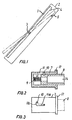
Fig. 1 shows a closed and a ventilation position of the sash, -
Fig. 2 is a sectional view through a locking device in a first preferred embodiment of the invention, -
Fig. 3 is a top view on the locking device shown inFig. 2 , -
Fig. 4 is a side view of the locking device shown inFig. 2 , -
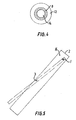
Fig. 5 shows the sash in another ventilation position, -
Fig. 6 is a top view on the window frame and sash with a detail showing the engagement of a latch with the locking device with the sash in a ventilation position, -
Fig. 7 is a sectional view through a second preferred embodiment of the locking device according to the invention, and -
Fig. 8 is a top view of a third preferred embodiment of the locking device according to the invention. - With reference to
Figs. 1 to 3 a pivot roof window according to the invention is an openable window with a window frame 2 and an openable sash 1. It is understood that the invention can be equally applied also to bottom hung windows in a substantially vertical facade. - The sash structure is pivotally journalled in the frame structure with an axis of rotation parallel with the top and bottom members by means of
pivotal hinges 3, known per se, between the frame 2 and sash 1. - Preferably, the frame and sash structures are for the major part built up by wood, although it is also possible to use metal or plastic. The sash 1 carries a
window pane 15. - In a closed position, the sash 1 is oriented substantially parallel with the window frame 2. In the closed position a locking mechanism (not shown) engages a recess 16 in the window frame to lock the window. The locking mechanism is operated by a handle 4. Such locking mechanisms are well known in the art and are therefore not shown in detail here.
- A ventilation position of the sash 1 at which it forms an acute angle with the window frame 2 is shown in broken lines in
Fig. 1 . Opening the sash 1 further is prevented by a locking device 5 which is described in more detail below. - As best shown in
Figs. 2 and 3 , the locking device 5 comprises a metal orplastic bushing 7 provided with a closed bottom and anannular rim 12 at its open end. The bushing is to mounted in a bore in frame 2. - A metal or plastic
cylindrical locking member 8 is slidably received in thebushing 7. Aspring 9, arranged between the bottom of thebushing 7 and the inner end of the lockingmember 8 urges the lockingmember 8 to an extended position, in which it obstructs the sash 1. The locking member is provided with abore 14 in which the latch 6 can be received when the lockingmember 8 is in a retracted position. - A radially outwardly protruding
pin 10 is fixed to the lockingmember 8. The pin extends into an L-shapedgroove 11 arranged in thebushing 7. In the retracted position thepin 10 is located at the end of the tangentially extending arm 11b of the L-shape groove 11, thus retaining the lockingmenber 8 in the retracted position. - In the extended position the
pin 10 is located in the axially extending arm 11a of the L-shapedgroove 11, and thus prevents the lockingmember 8 from being ejected from thebushing 7, as shown by the broken lines inFig. 3 . - The locking
member 8 can be moved from the retracted position to the extended position by turning the lockingmember 8 anti-clockwise and releasing it. The lockingmember 8 can be moved from the extended position by pressing it into thebushing 7 and turning it clockwise. - As best shown in
Fig. 4 , the lockingmember 8 is at its axial periphery provided with a serrated or grooved surface for improving frictional contact with an operator's fingers. - As the locking
member 8 cannot be reached from the outside it offers proper burglar protection. - Relatively broad types of windows may be provided with two locking devices 5, one at each side of the window frame 2, to improve structural stability.
- As best shown in
Figs. 5 and6 , the sash 1 can also be locked in a ventilation position by engaging the latch 6 withbore 14 in the lockingmember 7 when the latter is in the retracted position. - With reference to
Fig. 7 , another preferred embodiment of the locking device is shown. In this embodiment a radially inwardly protrudingpin 10 is fixed to thebushing 7. Thepin 10 is received in an L-shaped groove 11' provided in the locking member 6. The operation of moving the locking member between the retracted position and the extended position is the same as for the embodiment described above. - With reference to
Fig. 8 yet another preferred embodiment of the locking device is shown. An additional tangentially extending arm 11c has been added to the L-shapedgroove 11, thus forming a U-shaped groove. In the extended position, shown with broken lines inFig. 8 , thepin 10 is located at the end of the arm 11c and prevents the locking member from being pushed into thebushing 7. For moving the lockingmember 8 from the extended position to the retracted position, it is thus required to first turn the lockingmember 8 anticlockwise, press it into thebushing 7 and then turn it clockwise so that thepin 10 arrives at the end of the tangentially extending arm 11b. Arm 11c may also extend in the opposite direction so that the L-shapedgroove 11 becomes Z-shaped. A U- or Z-shaped groove can also be used when the groove is provided in the lockingmember 8 as described above. - The locking member may in another preferred embodiment (not shown) be provided with a key operated locking mechanism, such as a locking cylinder, to lock the locking member in the extended position and eventually also the retracted position.
- Although the present invention has been described in detail for purpose of illustration, it is understood that such detail is solely for that purpose, and variations and combination can be made therein by those skilled in the art without departing from the scope of the appended claims.
Claims (10)
- A pivot or bottom hung window comprising:- a window frame (2),- a sash (1) provided with a latch (6) for locking engagement with the window frame (2),- a bushing (7) mounted in the window frame (2),- an axially movable locking member (8) received in the bushing (7) having an extended active position in which it obstructs the sash (1) and a retracted inactive position in which it does not obstruct the sash (1), said locking member (8) being resiliently biased towards the extended position, and- means for retaining the locking member (8) in the retracted position,characterized in that the locking member (8) is provided with an axially opening recess (14) for receiving the latch (6) extending from the sash (1) when the locking member (8) is in the retracted position.
- A pivot or bottom hung window according to claim 1, characterized in that the means for retaining the locking member (8) in the retracted position is key-less.
- A pivot or bottom hung window according to claim 1 or 2, characterized in that the locking member (8) is provided with an radially outwardly extending pin (10) that engages a substantially L-shaped groove (11) in the bushing (7) for retaining the locking member (8) in the retracted position.
- A pivot or bottom hung window according to claim 1 or 2, characterized in that the locking member (8) is provided with an radially outwardly extending pin (10) that engages a substantially U- or Z-shaped groove (11) in the bushing (7) for retaining the locking member (8) in the retracted position and in the extended position.
- A pivot or bottom hung window according to claim 1 or 2, characterized in that the bushing (7) is provided with a radially inwardly extending pin (10) that engages a substantially L- shaped groove (11') in the locking member (8) for retaining the locking member (8) in the retracted position.
- A pivot or bottom hung window according to claim 1 or 2, characterized in that the bushing (7) is provided with a radially inwardly extending pin (10) that engages a substantially U- or Z-shaped groove (11') in the locking member for retaining the locking member (8) in the retraced position and in the extended position.
- A pivot or bottom hung window according to any of claims 1 to 6, characterised in that the bushing (7) is mounted in the frame (2) so that it faces the latch (6) when the sash (1) is in an open position.
- A pivot or bottom hung window according to any of claims 1 to 7, characterized in that said bushing (7) is provided with a radially inwardly extending pin (10) that engages a substantially U- or Z-shaped groove (11') in said locking member (8) for retaining said locking member (8) in said retracted position and in said extended position.
- A pivot or bottom hung window according to any of claims 1 to 8, characterized in that said bushing (7) is mounted such that the sash (1) can only be opened to a ventilation position when the locking member (8) is in its active position.
- A pivot or bottom hung window according to any of claims 1 to 9, characterized in that said bushing (7) is mounted such that the sash (1) can be locked in a ventilation position with the latch engaging the axially opening recess (14) in the locking member (8).
Applications Claiming Priority (3)
| Application Number | Priority Date | Filing Date | Title |
|---|---|---|---|
| DKPA200201219 | 2002-08-16 | ||
| DK200201219 | 2002-08-16 | ||
| PCT/EP2003/008931 WO2004018812A1 (en) | 2002-08-16 | 2003-08-12 | Window locking device |
Publications (2)
| Publication Number | Publication Date |
|---|---|
| EP1537285A1 EP1537285A1 (en) | 2005-06-08 |
| EP1537285B1 true EP1537285B1 (en) | 2009-07-01 |
Family
ID=31896774
Family Applications (1)
| Application Number | Title | Priority Date | Filing Date |
|---|---|---|---|
| EP03792303A Expired - Lifetime EP1537285B1 (en) | 2002-08-16 | 2003-08-12 | Window locking device |
Country Status (6)
| Country | Link |
|---|---|
| EP (1) | EP1537285B1 (en) |
| CN (1) | CN100360758C (en) |
| AT (1) | ATE435352T1 (en) |
| AU (1) | AU2003263213A1 (en) |
| DE (1) | DE60328203D1 (en) |
| WO (1) | WO2004018812A1 (en) |
Families Citing this family (5)
| Publication number | Priority date | Publication date | Assignee | Title |
|---|---|---|---|---|
| GB2455769B (en) * | 2007-12-20 | 2012-10-17 | Mighton Products Ltd | Sash window restrictor |
| DK2157262T3 (en) * | 2008-08-19 | 2017-09-11 | T J De Rooij Wood Design | Roof light window with theft protection |
| EP2674543A1 (en) | 2012-06-13 | 2013-12-18 | VKR Holding A/S | A roof window structure with a lock, and a lock for such a window |
| EP3216939A1 (en) * | 2012-12-07 | 2017-09-13 | Keystone Lintels Limited | A roof window with a locking apparatus |
| US10526829B2 (en) * | 2015-12-03 | 2020-01-07 | Lawrence E Chaffin | Lift glide door lock assembly and lift glide window lock assembly |
Family Cites Families (8)
| Publication number | Priority date | Publication date | Assignee | Title |
|---|---|---|---|---|
| US1940084A (en) * | 1932-07-16 | 1933-12-19 | Aley G Grasso | Window stop |
| DE1584058A1 (en) * | 1966-10-25 | 1970-03-26 | Hermann Burst | Stop and lock for doors |
| FR2428726A1 (en) * | 1978-06-16 | 1980-01-11 | Renault | GUIDE PLATE OR DOOR STOP |
| AU6886981A (en) * | 1980-03-31 | 1981-10-08 | Helen Kaye Brookfield | Door security bolt |
| CN87210993U (en) * | 1987-08-01 | 1988-04-13 | 华北石油管理局采油工艺研究所 | Special packer with retaining mechanism for bare borehole |
| CN2197439Y (en) * | 1994-08-15 | 1995-05-17 | 罗国华 | Self locking hinge for window |
| US6336245B1 (en) * | 1999-05-19 | 2002-01-08 | Souken Limited Company | Door stopper |
| FR2838767B1 (en) * | 2002-04-23 | 2004-08-13 | Omar Hanabal Kabri | DEVICE FOR PUSHING PORT GATES |
-
2003
- 2003-08-12 AU AU2003263213A patent/AU2003263213A1/en not_active Abandoned
- 2003-08-12 DE DE60328203T patent/DE60328203D1/en not_active Expired - Lifetime
- 2003-08-12 EP EP03792303A patent/EP1537285B1/en not_active Expired - Lifetime
- 2003-08-12 CN CNB038188732A patent/CN100360758C/en not_active Expired - Fee Related
- 2003-08-12 WO PCT/EP2003/008931 patent/WO2004018812A1/en not_active Ceased
- 2003-08-12 AT AT03792303T patent/ATE435352T1/en not_active IP Right Cessation
Also Published As
| Publication number | Publication date |
|---|---|
| DE60328203D1 (en) | 2009-08-13 |
| EP1537285A1 (en) | 2005-06-08 |
| CN100360758C (en) | 2008-01-09 |
| CN1675444A (en) | 2005-09-28 |
| ATE435352T1 (en) | 2009-07-15 |
| WO2004018812A1 (en) | 2004-03-04 |
| AU2003263213A1 (en) | 2004-03-11 |
Similar Documents
| Publication | Publication Date | Title |
|---|---|---|
| EP1907655B1 (en) | Security system for entrance barriers | |
| US6327879B1 (en) | Locking mechanism for sliding glass doors | |
| US7296831B2 (en) | Window lock keeper | |
| US7255375B2 (en) | Reach out lock | |
| US9003706B2 (en) | Key lockable operator cover | |
| US5102173A (en) | Reenforcer for doors and windows | |
| AU2014203791B2 (en) | Sliding door or window latch | |
| US3954292A (en) | Door latch with turnable lock button | |
| KR20160052486A (en) | Lock device for sliding type fittings | |
| EP1537285B1 (en) | Window locking device | |
| GB2455777A (en) | Locking system with hook, main locking unit, secondary locking unit and common through bar | |
| US10329802B1 (en) | Lock mechanism | |
| EP2674544B1 (en) | An openable window with a lock | |
| US4524590A (en) | Door latch with lock | |
| US2613524A (en) | Locking mechanism for window latches | |
| US4275910A (en) | Door latch | |
| GB2209367A (en) | Security device | |
| KR100427402B1 (en) | Locking apparatus for opening and shutting door | |
| CN100510302C (en) | Lock device and door window apparatus | |
| JP2005097866A (en) | Locking device by handle operation | |
| KR960004845Y1 (en) | Door and door lock | |
| GB2424033A (en) | A fastener, particularly a sash window lock | |
| EP3647517A1 (en) | Lock guard for locks with an enhanced security | |
| AU2021282434A1 (en) | Multi-Functional Entrance Lock | |
| JP2005105563A (en) | Lock device for opening/closing body of casement window |
Legal Events
| Date | Code | Title | Description |
|---|---|---|---|
| PUAI | Public reference made under article 153(3) epc to a published international application that has entered the european phase |
Free format text: ORIGINAL CODE: 0009012 |
|
| 17P | Request for examination filed |
Effective date: 20050316 |
|
| AK | Designated contracting states |
Kind code of ref document: A1 Designated state(s): AT BE BG CH CY CZ DE DK EE ES FI FR GB GR HU IE IT LI LU MC NL PT RO SE SI SK TR |
|
| AX | Request for extension of the european patent |
Extension state: AL LT LV MK |
|
| DAX | Request for extension of the european patent (deleted) | ||
| RAP1 | Party data changed (applicant data changed or rights of an application transferred) |
Owner name: VKR HOLDING A/S |
|
| GRAJ | Information related to disapproval of communication of intention to grant by the applicant or resumption of examination proceedings by the epo deleted |
Free format text: ORIGINAL CODE: EPIDOSDIGR1 |
|
| GRAP | Despatch of communication of intention to grant a patent |
Free format text: ORIGINAL CODE: EPIDOSNIGR1 |
|
| GRAP | Despatch of communication of intention to grant a patent |
Free format text: ORIGINAL CODE: EPIDOSNIGR1 |
|
| GRAS | Grant fee paid |
Free format text: ORIGINAL CODE: EPIDOSNIGR3 |
|
| GRAA | (expected) grant |
Free format text: ORIGINAL CODE: 0009210 |
|
| AK | Designated contracting states |
Kind code of ref document: B1 Designated state(s): AT BE BG CH CY CZ DE DK EE ES FI FR GB GR HU IE IT LI LU MC NL PT RO SE SI SK TR |
|
| REG | Reference to a national code |
Ref country code: GB Ref legal event code: FG4D |
|
| REG | Reference to a national code |
Ref country code: CH Ref legal event code: EP |
|
| REG | Reference to a national code |
Ref country code: IE Ref legal event code: FG4D |
|
| REF | Corresponds to: |
Ref document number: 60328203 Country of ref document: DE Date of ref document: 20090813 Kind code of ref document: P |
|
| PG25 | Lapsed in a contracting state [announced via postgrant information from national office to epo] |
Ref country code: SI Free format text: LAPSE BECAUSE OF FAILURE TO SUBMIT A TRANSLATION OF THE DESCRIPTION OR TO PAY THE FEE WITHIN THE PRESCRIBED TIME-LIMIT Effective date: 20090701 |
|
| PG25 | Lapsed in a contracting state [announced via postgrant information from national office to epo] |
Ref country code: FI Free format text: LAPSE BECAUSE OF FAILURE TO SUBMIT A TRANSLATION OF THE DESCRIPTION OR TO PAY THE FEE WITHIN THE PRESCRIBED TIME-LIMIT Effective date: 20090701 Ref country code: SE Free format text: LAPSE BECAUSE OF FAILURE TO SUBMIT A TRANSLATION OF THE DESCRIPTION OR TO PAY THE FEE WITHIN THE PRESCRIBED TIME-LIMIT Effective date: 20090701 Ref country code: ES Free format text: LAPSE BECAUSE OF FAILURE TO SUBMIT A TRANSLATION OF THE DESCRIPTION OR TO PAY THE FEE WITHIN THE PRESCRIBED TIME-LIMIT Effective date: 20091012 Ref country code: AT Free format text: LAPSE BECAUSE OF FAILURE TO SUBMIT A TRANSLATION OF THE DESCRIPTION OR TO PAY THE FEE WITHIN THE PRESCRIBED TIME-LIMIT Effective date: 20090701 Ref country code: EE Free format text: LAPSE BECAUSE OF FAILURE TO SUBMIT A TRANSLATION OF THE DESCRIPTION OR TO PAY THE FEE WITHIN THE PRESCRIBED TIME-LIMIT Effective date: 20090701 |
|
| PG25 | Lapsed in a contracting state [announced via postgrant information from national office to epo] |
Ref country code: BG Free format text: LAPSE BECAUSE OF FAILURE TO SUBMIT A TRANSLATION OF THE DESCRIPTION OR TO PAY THE FEE WITHIN THE PRESCRIBED TIME-LIMIT Effective date: 20091001 Ref country code: PT Free format text: LAPSE BECAUSE OF FAILURE TO SUBMIT A TRANSLATION OF THE DESCRIPTION OR TO PAY THE FEE WITHIN THE PRESCRIBED TIME-LIMIT Effective date: 20091102 Ref country code: MC Free format text: LAPSE BECAUSE OF NON-PAYMENT OF DUE FEES Effective date: 20090831 |
|
| REG | Reference to a national code |
Ref country code: CH Ref legal event code: PL |
|
| PG25 | Lapsed in a contracting state [announced via postgrant information from national office to epo] |
Ref country code: RO Free format text: LAPSE BECAUSE OF FAILURE TO SUBMIT A TRANSLATION OF THE DESCRIPTION OR TO PAY THE FEE WITHIN THE PRESCRIBED TIME-LIMIT Effective date: 20090701 Ref country code: CZ Free format text: LAPSE BECAUSE OF FAILURE TO SUBMIT A TRANSLATION OF THE DESCRIPTION OR TO PAY THE FEE WITHIN THE PRESCRIBED TIME-LIMIT Effective date: 20090701 Ref country code: CH Free format text: LAPSE BECAUSE OF NON-PAYMENT OF DUE FEES Effective date: 20090831 Ref country code: DK Free format text: LAPSE BECAUSE OF FAILURE TO SUBMIT A TRANSLATION OF THE DESCRIPTION OR TO PAY THE FEE WITHIN THE PRESCRIBED TIME-LIMIT Effective date: 20090701 Ref country code: LI Free format text: LAPSE BECAUSE OF NON-PAYMENT OF DUE FEES Effective date: 20090831 |
|
| PLBE | No opposition filed within time limit |
Free format text: ORIGINAL CODE: 0009261 |
|
| STAA | Information on the status of an ep patent application or granted ep patent |
Free format text: STATUS: NO OPPOSITION FILED WITHIN TIME LIMIT |
|
| PG25 | Lapsed in a contracting state [announced via postgrant information from national office to epo] |
Ref country code: SK Free format text: LAPSE BECAUSE OF FAILURE TO SUBMIT A TRANSLATION OF THE DESCRIPTION OR TO PAY THE FEE WITHIN THE PRESCRIBED TIME-LIMIT Effective date: 20090701 |
|
| 26N | No opposition filed |
Effective date: 20100406 |
|
| PG25 | Lapsed in a contracting state [announced via postgrant information from national office to epo] |
Ref country code: IE Free format text: LAPSE BECAUSE OF NON-PAYMENT OF DUE FEES Effective date: 20090812 |
|
| PG25 | Lapsed in a contracting state [announced via postgrant information from national office to epo] |
Ref country code: GR Free format text: LAPSE BECAUSE OF FAILURE TO SUBMIT A TRANSLATION OF THE DESCRIPTION OR TO PAY THE FEE WITHIN THE PRESCRIBED TIME-LIMIT Effective date: 20091002 |
|
| PGFP | Annual fee paid to national office [announced via postgrant information from national office to epo] |
Ref country code: NL Payment date: 20100813 Year of fee payment: 8 |
|
| PGFP | Annual fee paid to national office [announced via postgrant information from national office to epo] |
Ref country code: IT Payment date: 20100824 Year of fee payment: 8 |
|
| PG25 | Lapsed in a contracting state [announced via postgrant information from national office to epo] |
Ref country code: LU Free format text: LAPSE BECAUSE OF NON-PAYMENT OF DUE FEES Effective date: 20090812 |
|
| PG25 | Lapsed in a contracting state [announced via postgrant information from national office to epo] |
Ref country code: HU Free format text: LAPSE BECAUSE OF FAILURE TO SUBMIT A TRANSLATION OF THE DESCRIPTION OR TO PAY THE FEE WITHIN THE PRESCRIBED TIME-LIMIT Effective date: 20100102 |
|
| PG25 | Lapsed in a contracting state [announced via postgrant information from national office to epo] |
Ref country code: TR Free format text: LAPSE BECAUSE OF FAILURE TO SUBMIT A TRANSLATION OF THE DESCRIPTION OR TO PAY THE FEE WITHIN THE PRESCRIBED TIME-LIMIT Effective date: 20090701 |
|
| PG25 | Lapsed in a contracting state [announced via postgrant information from national office to epo] |
Ref country code: CY Free format text: LAPSE BECAUSE OF FAILURE TO SUBMIT A TRANSLATION OF THE DESCRIPTION OR TO PAY THE FEE WITHIN THE PRESCRIBED TIME-LIMIT Effective date: 20090701 |
|
| REG | Reference to a national code |
Ref country code: NL Ref legal event code: V1 Effective date: 20120301 |
|
| PG25 | Lapsed in a contracting state [announced via postgrant information from national office to epo] |
Ref country code: IT Free format text: LAPSE BECAUSE OF NON-PAYMENT OF DUE FEES Effective date: 20110812 Ref country code: NL Free format text: LAPSE BECAUSE OF NON-PAYMENT OF DUE FEES Effective date: 20120301 |
|
| PGFP | Annual fee paid to national office [announced via postgrant information from national office to epo] |
Ref country code: BE Payment date: 20120820 Year of fee payment: 10 |
|
| BERE | Be: lapsed |
Owner name: VKR HOLDING A/S Effective date: 20130831 |
|
| PG25 | Lapsed in a contracting state [announced via postgrant information from national office to epo] |
Ref country code: BE Free format text: LAPSE BECAUSE OF NON-PAYMENT OF DUE FEES Effective date: 20130831 |
|
| REG | Reference to a national code |
Ref country code: FR Ref legal event code: PLFP Year of fee payment: 14 |
|
| REG | Reference to a national code |
Ref country code: FR Ref legal event code: PLFP Year of fee payment: 15 |
|
| REG | Reference to a national code |
Ref country code: FR Ref legal event code: PLFP Year of fee payment: 16 |
|
| PGFP | Annual fee paid to national office [announced via postgrant information from national office to epo] |
Ref country code: FR Payment date: 20210727 Year of fee payment: 19 |
|
| PGFP | Annual fee paid to national office [announced via postgrant information from national office to epo] |
Ref country code: DE Payment date: 20210706 Year of fee payment: 19 Ref country code: GB Payment date: 20210707 Year of fee payment: 19 |
|
| REG | Reference to a national code |
Ref country code: DE Ref legal event code: R119 Ref document number: 60328203 Country of ref document: DE |
|
| GBPC | Gb: european patent ceased through non-payment of renewal fee |
Effective date: 20220812 |
|
| PG25 | Lapsed in a contracting state [announced via postgrant information from national office to epo] |
Ref country code: FR Free format text: LAPSE BECAUSE OF NON-PAYMENT OF DUE FEES Effective date: 20220831 Ref country code: DE Free format text: LAPSE BECAUSE OF NON-PAYMENT OF DUE FEES Effective date: 20230301 |
|
| PG25 | Lapsed in a contracting state [announced via postgrant information from national office to epo] |
Ref country code: GB Free format text: LAPSE BECAUSE OF NON-PAYMENT OF DUE FEES Effective date: 20220812 |