EP1536572A1 - Netzleitungsübertragungssystem - Google Patents
Netzleitungsübertragungssystem Download PDFInfo
- Publication number
- EP1536572A1 EP1536572A1 EP03026995A EP03026995A EP1536572A1 EP 1536572 A1 EP1536572 A1 EP 1536572A1 EP 03026995 A EP03026995 A EP 03026995A EP 03026995 A EP03026995 A EP 03026995A EP 1536572 A1 EP1536572 A1 EP 1536572A1
- Authority
- EP
- European Patent Office
- Prior art keywords
- time
- control
- digital information
- date
- receiving device
- Prior art date
- Legal status (The legal status is an assumption and is not a legal conclusion. Google has not performed a legal analysis and makes no representation as to the accuracy of the status listed.)
- Withdrawn
Links
Images


Classifications
-
- H—ELECTRICITY
- H04—ELECTRIC COMMUNICATION TECHNIQUE
- H04B—TRANSMISSION
- H04B3/00—Line transmission systems
- H04B3/54—Systems for transmission via power distribution lines
-
- H—ELECTRICITY
- H04—ELECTRIC COMMUNICATION TECHNIQUE
- H04B—TRANSMISSION
- H04B3/00—Line transmission systems
- H04B3/54—Systems for transmission via power distribution lines
- H04B3/56—Circuits for coupling, blocking, or by-passing of signals
-
- H—ELECTRICITY
- H04—ELECTRIC COMMUNICATION TECHNIQUE
- H04B—TRANSMISSION
- H04B2203/00—Indexing scheme relating to line transmission systems
- H04B2203/54—Aspects of powerline communications not already covered by H04B3/54 and its subgroups
- H04B2203/5429—Applications for powerline communications
- H04B2203/5458—Monitor sensor; Alarm systems
Definitions
- the present invention relates to a system for transmitting digital information via a power supply network and using this information to control and/or enhance electronic devices.
- Electricity at 50Hz or 60Hz is normally distributed by a 3 phase 11KV or 33KV network distribution network. Its final step is to pass through neighbourhood transformers which drop the voltage down to typically either a nominal 110V or 240V ⁇ /N for use by the networks retail customers.
- the AC Power distribution Network looking downstream behaves as a very low pass filter, i.e. it attenuates frequencies sharply much above 100Hz and by 1400Hz transmission at regulated voltages is all but impossible. This is primarily due to cumulative noise generated by all devices attached to the power network. Such electrical noise eventually swamps even the most sophisticated modulation schemes.
- AC Power is a commodity that can not be stored.
- 'Ripple Control' a very low speed on/off semaphore messaging system, to signal control equipment located in the consumers meter-box.
- the utility uses this signal to control blocks of network load of the same type, i.e. to turn hot water heaters on and off during times of peak load.
- the electricity supply company promises to provide electricity with a very high availability on 'time of day' and/or use based tariffs. Nominally amplitude variations of the AC signal are regulated to not exceed a fluctuation of +/- 5% which may otherwise occur due to surge, disruption, sudden load spikes caused elsewhere in the network, or even the cumulative effect of AC motors in a large number of residential commercial and industrial appliances.
- power companies use 'Ripple Control', currently operating under these regulatory constraints, to transmit their own control signals throughout the network. These signals normally are detected by sealed control relays in the customers meter box which result in turning off or on all ripple control relay circuits set to the transmitted code.
- Ripple Injection systems normally use short fixed duration bursts of a single frequency within a fixed 8 or 16 slot time window.
- the resulting 'code' is a binary number matched to a receiver controlling an on/off relay at all customer premises based normally on the type of controlled load.
- Ripple injection messages are usually measured in signals per hour where each signal can typically take 6 to 12 seconds to transmit in effect 8 bits of data. This results in ripple control being useless as a general messaging system with its total throughput measured in bits per hour.
- the receivers are also bulky and expensive and not suited to the kind of automation that a customer would use.
- Enermet is a major European manufacturer of ripple injection 'plant' that is used around the world.
- Current technology uses solid-state electronics devices matched to the distribution feeder voltage nominally at 11KV, to add the ripple control signals. These devices can not operate continuously for prolonged periods due to overheating and have short life expectancies for a very expensive and functionally crucial device to the power company if they are used frequently.
- the problems continue downstream in distributing an IP type Internet network using the Power Network.
- Adaptive Networks Inc. uses a spread spectrum approach to include modulated bandwidth that excludes interference. This other than complexity and cost also suffers limited distribution distance due to attenuation and interference.
- a transmission device for transmitting digital information via a power supply network according to independent claim 1 a receiving device for receiving digital information via a power supply network according to independent claim 8, a method for transmitting digital information via a power supply network according to independent claim 16, and a method for receiving digital information via a power supply network according to independent claim 19.
- Preferred embodiments thereof are respectively defined in the respective following dependent claims.
- a transmission device for transmitting digital information via a power supply network comprises
- a receiving device for receiving digital information via a power supply network comprises
- a method for transmitting digital information via a power supply network comprises the steps of:
- a method for receiving digital information via a power supply network comprises the steps of:
- the present invention operates similarly to a ripple control system, at or below the same tolerances that existing ripple equipment operates. This is deliberate as incorporating these factors into the design reduces the certification requirements for deploying transmitters according to the present invention.
- the present invention took advantage of being able to produce a unique and specialised approach to signalling in the Power network, namely not to use expensive dynamic frequency splitting to increase the bit rate of a digital signal, but to seek robustness in using frequencies and minimal harmonics thereof emulating a digital signal not attenuated by the network and those not being interfered with by other electrical devices.
- Using only predetermined harmonics of the signalling frequency simplifies the detection circuitry and also minimises interference created from the transmitter although generally only lower data throughput rates are achieved in comparison to the dynamic frequency splitting.
- the design and resulting circuit designs according to the present invention are extremely robust to give longevity and enable them to be embedded within the AC powered appliance's power supply.
- the signal transmitted using the present invention will be detectable within the power supply of any electrical appliance or device connected to the AC power source.
- the present invention does not affect ripple control receivers or equipment attached to the power system.
- the present invention does not address the bi-directional or IP markets, but transmits a proprietary modulation and data format. It is unidirectional and broadcast in nature unlike that used within power system based IP based (Internet) networks that have been tried to date. As set-out, the present invention is not simply the downstream piece of an IP based system.
- the present invention includes the physical integration to using only predetermined harmonics of the signalling frequency and through the possible and preferred use of cryptography techniques making an individual pathway between the transmitting device and a signal receiving device. The present invention thusly describes a much refined messaging system as it propagates freely anywhere there is an electrical power circuit, and without the need for other termination device or modifications to existing wiring.
- the signal transmitting device design according to the present invention maximises the signals robustness at the receiving device interface according to the present invention based on being able to match exactly the electrical propagation characteristics of the transmission network to the programmable wave-form of the (high voltage) transmitter according to the present invention.
- the characteristics of the modulation and transmission according to the present invention include the following:
- said high-voltage injector preferably comprises
- the method for transmitting digital information via a power supply network preferably comprises the step of rapidly turning drive stage transistors on and off in conformance with the shape of the low frequency wave-form, in particular at a frequency greater than 6 kHz.
- this preferred embodiment according to the present invention offers a new system of rapidly switching the drive stage transistors, in the following referred to as 'chopping'.
- Chopping involves rapidly turning the drive stage transistors on and off in conformance with the shape of the low frequency wave-form. Turning the transistors on and off at greater than 6 kHz, and being able to vary the message duty cycle based on the specific network condition, a nearly '100% on' or signalling condition is approached. This also reduces the power rating of the injection device or any matching transformer connected to the power distribution network.
- This preferred embodiment according to the present invention enables cooling the active system if required by altering the on/off or chopping duty cycle, or by reducing the message transmission rate down to a level to maintain just the date/time updates.
- the chopping also reduces heating and the power consumption by around 50% transmitting actually only 1 ⁇ 2 the time and dramatically increasing the life expectancy of the equipment.
- the high frequency switching or chopping component is rapidly attenuated in the network within 500 metres and is not seen by the receivers according to the present invention at all.
- This preferred signal transmitting device design and preferred method for transmitting digital information via a power supply network improves a high voltage transmitter's power efficiency by more than 50%, achieving continuous transmission where other signalling transmission systems such as Ripple Control typically operate inefficiently at less than 1% utilisation with a much lower effective data rate.
- the transmission device according to the present invention further preferably comprises
- the method for transmitting digital information via a power supply network further preferably comprises the steps of detecting specific conditions of the power supply network, and varying the chopping on/off cycle of the drive stage transistors accordingly and/or shutting down and turning on the drive stage transistors accordingly.
- said predetermined harmonic frequencies of the signal frequency preferably include the first and third harmonic frequencies of the signal frequency.
- a logic '1' might be defined as the primary signalling frequency and the negative cycle of the third harmonic at a predetermined first signal level, preferably - 8dB
- a logic '0' might be defined as the negative cycle of the third harmonic at a predetermined second signal level, preferably -6dB, preferably respectively preceded by a synchronisation preamble at a higher frequency, preferably of some higher harmonic of the signal frequency.
- said digital information preferably is
- said digital information is preferably used
- said digital information might be used to transmit a synchronized date and time to update automatically and continuously a date and time to electrically powered devices using the power supply network for transmission.
- control technology possible according to the present invention gives a power company the ability to easily securely and cheaply address a single customer's circuit, or a single appliance.
- the receiving device preferably comprises an optical interface arranged in an output path of the logic device. Such an optical isolation is used to protect attached digital devices from interference from or to the power supply.
- the receiving device alternatively or additionally preferably comprises an information retrieval unit to retrieve control information directed to said particular receiving device.
- the method for receiving digital information via a power supply network preferably comprises the step of retrieving control information directed to said particular receiving device.
- said information retrieval unit preferably comprises a decryption unit to verify whether or not said control information is addressed to said particular receiving device and to decrypt said control information with a predetermined key.
- the method for receiving digital information via a power supply network further preferably comprises the step of verifying whether or not said control information is addressed to a particular receiving device and to decrypt said control information with a predetermined key.
- the present invention preferably enables a method for transmitting control information using no explicit address.
- the receiving device is preferably integrated in a personal computer or other electronic device displaying or using date and time or private control information or instructions.
- the receiving device it is preferred that the receiving device according to the present invention
- OnTime describes a 'Method' for continuously transmitting a Date and Time synchronisation signal to clocks and electronic appliances using or displaying time.
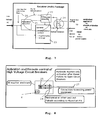
- Figure 1 shows an arbitrary AC Power reticulation network, comprising a very high voltage generation and distribution network 1 and a neighbourhood AC power distribution 2, which are connected via a power substation 3.
- OnTime will operate when added to any existing power network, anywhere in the world, with respect to the licensing, safety, voltages and frequencies used in the distribution of electricity.
- Figure 1 also shows specifically how the Date/Time function is effected, namely by feeding an atomic clock signal via a signal transmission device 4 and the power substation 3 into the power network.
- the Signal transmission device 4 adjusts the actual time for insertion, propagation and processing delays, amplifies this signal and adds the amplified signal to the power distribution grid by signal injection equipment.
- Date/Time being the primary function of this preferred embodiment.
- a receiver 5 that is attached to an equipment AC/DC power supply 5a can supply serial date/time information via the actual receiving device 6 to an embedded time display controller logic 5b and/or authenticated directives/instructions to an embedded logic appliance control 5c.
- OnTime a low speed data stream comprising logic '0's and logic '1's is broadcast continuously over the AC Power distribution network.
- a date and time signal e.g. synchronised off an atomic clock so that sub second accuracy is achieved with signals synchronised on the last transmitted bit.
- a receiving device that is embedded into the OnTime system as also shown in figure 2, in which the same reference numbers as shown in figure 1 denote the same components, and that is integrated into the power supply of electrical devices demodulates and passes a digital sequence to the control or display electronics driving clocks, electronic devices and electrical appliances.
- the OnTime system is able to send and demodulate a continuous digital-data stream 8 via an OnTime injector 4b that is part of the transmission device 4 anywhere within the Electricity Distribution Network. It attaches anywhere AC cabling is run and its robustness and low cost make it easily included into every power supply 5a or connect to an appliance 7.
- FIG 3 in which the same reference numbers as shown in figures 1 and 2 denote the same components, again shows the OnTime components.
- a high voltage, transmission device 4 that includes a power injector 4b and a transmitter device 4a to generate the digital signal that is amplitude modulated ⁇ 5% total voltage distortion, uses a robust modulation scheme to broadcast a date and time synchronisation signal throughout the power distribution network.
- a simple OnTime receiving device 6, located within any electrical appliance power supply demodulates a low voltage (nominally 20V RMS +/-) synchronised date/time signal 9 or an owner initiated and authenticated control message 10 and passes them to an attached clock or appliance.
- the receiving device 7a has a storage, a decryption unit and a data manipulation unit. It receives a serial number, encryption keys and digital data and outputs an unencrypted control signal and/or the date/time signal.
- OnTime technology provides value added in the operation and use of any AC powered appliance and equipment manufacturers can use it for one or both of the following applications:
- For a time display device when the power is on the clock will show accurate time automatically without human intervention. This includes immediately after any OnTime capable device is first plugged in, or when power returns after an outage.
- Date and Time is broadcast on regular sub-second intervals to update clocks.
- Control signals are transmitted by the power company on customer demand following strict manufacturer, legal i.e. monitoring, and definition of owner or normal user of such equipment or appliance and guidelines for registration and use of the system.
- the 'Type I' 'Receiver Device' demodulates a serial date and time data stream and relays it via a custom serial output data line to a directly connected clock, appliance, or other electronic or control circuitry. This is the case when an OnTime equipped ON/OFF Power Switch is used to turn an electrical appliance on or off.
- the connection will be directly to the microprocessor, or even the 7 Segment display controller for the time piece.
- the reference signal can be accessed immediately once the device has its AC power either turned on, or restored following a power outage (occurs within 0.1 to 0.3s).
- the refresh timing will depend on the device or appliance incorporating the OnTime technology.
- the intervals are based on the appliance's own functional design requirements.
- the frequency and way in which the time is synchronised is more important for recording and event driven devices such as alarm clocks, DVD's, VCRs and computers, then it is for microwaves, ovens, washing-machines, refrigerators and other such appliances that may show current time, as only the default display when not in use or in a turned 'off', what is typically referred to as standby mode, but still with a closed circuit path to the AC power source.
- the OnTime Type I device does not support encryption. However in the receiver's more advanced 'Type II' form it has intelligence with a 'unique serial number', a private encryption key and an elaborate message authentication process which is used as part of the addressing and validation scheme.
- the signal reception and demodulation function is part of the front end or 'Type I' device.
- An OnTime Type II device can also output a verified and unspecified control signal to a specific electrical appliance to do any legal action the manufacturer has designed and licensed. Such messages can be used for any function such as regulating the operation of an appliance remotely, or instigating a cause and effect action all within the secure operational constraints, reliability, and comfort offered by the customers Electricity Company or utility.
- the device can also improve the time accuracy of the relayed date and time signal.
- the Type II receiver has numerous other control uses, too many to start to describe. Apart from initiating remote self test diagnostics and enabling or disabling equipment the owner of an OnTime equipped appliance can for example, turn a specific device on or off, or adjust an automated temperature setting or cycle. The technology could be used just as easily for a manufacturer to dump a log, do diagnostics and then call-back or email the results to a telephone number or address included in the control message.
- OnTime service might ask their utility to adjust the setting on their heating or cooling at home, or turn appliances or circuits on or off. They could even control a security lockout of all their electric gates, doors, portable phones and other devices related to the security of their home or office while they are away on holiday, or otherwise geographically isolated.
- An aspect of the security and safety of the OnTime system is that such actions are usually timely and ultimately verifiable by some phenomenon observed by a human being.
- OnTime these types of functions can be achieved by the customer making a single free call to their local power utility, then identifying themselves and asking for a holiday mode 80 degrees F setting to be sent to their air conditioning unit, or in winter a 50 degree setting for their heater. Or a restocking request to go to any company e.g. such as XYZ for their refrigerator. Or a request, adhering strictly to copyright and other local legalities, for their DVD to record a cable Pay-Per-View program while they are away. Perhaps the customer also pre-registered specific messages and restricted only those to be ever transmitted.
- the default mode for a new serial number device entered into the OnTime system is that it can't do anything without a predefined message and human intervention. So they might just ask for their intelligent refrigerator to reschedule delivery for the day before they return home, earlier than expected from their vacation. Convenience and peace of mind are integral parts of the OnTime system.
- Value added services provided by the 'Power Company' can therefore form an intrinsic part of the use of the OnTime system.
- Equipment manufacturers will integrate the OnTime Type II technology and register the digital injection sequences that can be sent to their device, additional values required and the action the appliance will take after receiving the authenticated control instruction.
- the customer will have to provide the OnTime receiver serial number included in their appliance to use the remote control capability. Without registering the device with the Power Company having first retrieved the embedded serial number from any OnTime receiver, which is needed to send any control message, the OnTime functionality is inert except for the unencrypted Date and Time function. As a result such unregistered device could not be used, or as importantly accidentally used.
- the registration process may require physical access to the appliance or be provided by the appliance manufacturer at the customers request.
- the OnTime project applies numerous electrical engineering theories and experience to extend the signalling beyond the typical on-off, single frequency low signalling rate of ripple control which is also unidirectional with unacknowledged messages.
- the method defined in this embodiment of the present invention will result in radical commercialisation and use of the broadcast of a date and time signal by any electrical equipment that would use an accurate time reference.
- clocks for example, if a manufacturer implements OnTime support in their equipment according to license requirements, then if the AC power is on the displayed time is correct to a sub-second accuracy.
- the OnTime implementation includes features so that alarm clocks won't loose an alarm event even if a brief power interruption occurred prior to the set alarm, even if the clock had a malfunctioning or non-existent battery backup. Obviously the time will have reset when the power was reinstated. In this case if the whole house is OnTime ready the blissfully sleeping customer won't even know there was a power failure while they slept. No more waking up or coming home from work to a house full of blinking digital clocks on every appliance in the house. No more having all the clocks in the house display different times. No more worrying if you set am or pm on the DVD or VCR to record the Pay-Per-View program you forgot to order.
- connection between the transmitter and receiver is very low bandwidth and is constrained to analogue frequencies between 65Hz and 1400Hz to minimise propagation loss and interference from other electrical devices.
- the low pass characteristic of the AC power network results in significant attenuation above 1400Hz.
- Experience shows unreliable transmission of single frequency ripple frequencies above 750 Hz for a 50Hz system or 900Hz for a 60Hz power network due to interference from banks of fluorescent lighting and AC motors which have peaks in their harmonic interference at odd multiples of the exciting frequency at and above for example the 15th or 19 th harmonic.
- a low voltage AC 'receiving device' is designed that is capable of demodulating the low speed digital signal broadcast from a high voltage transmitter located anywhere above it within the AC power reticulation (or distribution) network.
- the OnTime design takes into account interference from fluorescent lighting, AC motors and other sources, as well as the network's low pass filtering characteristic and currently operates at lower frequencies then those interference sources. The result is a closely integrated, robust, very low voltage modulation, transmission and reception design.
- OnTime seeks to reduce the certification process for the equipment to be deployed.
- OnTime includes the broadcast of a date and time pulse to be picked up by receivers embedded in the power supplies of clocks, appliances and other AC powered equipment.
- OnTime, Binary Coded Decimal format transmitted is designed to minimise the signal insertion and message propagation delay for a low speed digital network.
- OnTime will nominally operate at data rates of between 300bps and 2000bps and transmit a signal that will also be directly compatible with most current 7 segment driver chip designs.
- These IC's and PCB designs can directly attach to the OnTime receiver output lead, by using a newly designated external pin on the individual appliance manufacturers IC or printed circuit board.
- the 'receiving device' design is intended to minimise the development, tooling and production costs of integrating OnTime into existing integrated circuit designs.
- OnTime receiver becomes physically tied to the internal logic of the receiving Integrated Circuit the internal design carefully considers and uses a fail-safe aspect of sharing dual access to a common shift register or memory location depending on the sophistication of the chip incorporating the OnTime line interface receiver.
- a signalling structure that uses and can detect the 1 st and 3 rd harmonics of a signalling frequency at a particular threshold. This gives more noise tolerance and less sensitivity required at the detector then would be needed to detect a pure square wave where the third harmonic is -9.2dB which for us would be about 20mV on our 20V AC input signal waveform.
- a message synchronising reset is 2 complete cycles of F3 at - 9.45dB for a 'Control' instruction or the absence of F3, the third harmonic, detected for a continuous period exceeding 28mS at a 167Hz primary signalling frequency.
- the PAL logic shown in Figure 7 can be programmed to separate or maintain the 5 th harmonic preamble to a logic bit.
- the preamble is the positive cycle of F5, the fifth harmonic or similar frequency at a signal level of -6.7dB with an optional signalling break condition, e.g. 0.3mS.
- a pulse of higher frequency is used to synchronise the detector for an incoming data-bit. This allows to use a variable bit length and increase the data throughput rate, as well as to reduce the effects of noise in the scheme when using very low modulation voltages.
- a square wave is comprised of an infinite number of odd multiples of the fundamental frequency.
- the magnitude of the components is according to Table 1. 'Fourier Sequence Square Wave Coefficients' Exponential Form Fourier Series coefficients. Harmonic Signal (dBm) First F1 0 Third F3 -9.54 Fifth F5 -13.98
- the third harmonic is already 9.54 dB lower than the fundamental or signalling frequency at approximately 12% and the fifth harmonic is nearly 14dB down or 3% of the primary or fundamental signalling frequency, a square-wave represented by only propagating partial wave-forms comprising the first and third harmonics is reproduced.
- the third harmonic is set at a higher signal level than in Table 1, and the phase of the individual frequencies get aligned, since the Transmission device allows an almost arbitrary modulation wave form. This again increases the effective signalling rate in the restrictive operational environment. The result thereof is a more robust implementation of the signal detection in which the overall signal level of the OnTime signal can be dropped and the efficiency of the transmitter can be further improved.
- the resulting circuit designs are extremely robust to give longevity and enable them to be embedded within the AC powered appliance's power supply.
- operators of AC powered appliances are restricted access to the dangerous AC voltages of the electricity supply itself in consideration of safety.
- any AC transformers powering the device are separately enclosed or use a floating earth, i.e. are 'double insulated' or have some other physical isolation in their design making attempted access difficult and dangerous.
- 2 DC voltages provided by the external device or printed circuit board are preferably used.
- An optical isolation is provided to restrict noise and to de-couple the IC silicon wafer from the AC power network. These 2 voltages represent both OnTime's and the IC's shared logic levels.
- a '1' is preferably the primary signalling frequency and the negative cycle of the third harmonic at a level of -8dB immediately following a synchronisation preamble at a higher frequency.
- a '0' according to this shown and described preferred exemplary embodiment is preferably the negative cycle of the third harmonic at a level of -6dB immediately following a synchronisation preamble at a higher frequency.
- Each Message type preferably begins with a unique defining reset condition.
- OnTime uses a Binary Coded Decimal format to minimise the signal injection/propagation delay in a low speed digital network.
- the format is also more directly compatible with most current 7 Segment Driver Chip designs so the manufacturer can chose a point of minimal processing to use the reference date and time in their products.
- the transmitter design includes a local connection to a control terminal.
- the control terminal pre-configures, corrects and synchronises the signal for the gate control logic program firing the high power solid state transistors in the device.
- a hot standby is configured. Logging of all messages is performed for system and law enforcement purposes.
- the control terminal will use a dual path either Internet or direct link to a reference source, e.g. an Atomic Clock. This is based on the ability of the data network configuration at the power company location to determine the actual propagation delay which must be accounted for in the broadcast time.
- a reference source e.g. an Atomic Clock.
- the receiver technology will likely be partially integrated into the chip-sets of the appliances and electrical devices equipped with OnTime, with the front end of the Type I 'Receiver' portion contained within the AC Step-down power transformer energising the equipment.
- the Date/Time Type I system minimises the costs for embedded chip manufacturers to use OnTime and migrate the function directly into their integrated circuits. In this case the receiver will pass all binary data through and not block non system control signals.
- OnTime will be portable when incorporated into any electrical device and could form one of the features of an auto-voltage sensing power supply or a PC or any appliance power supply.
- the basic Type I device will automatically use local time as broadcast by the local electricity supplier with no configuration required.
- the receiving device can easily be achieved in numerous ways using either analogue or digital components.
- a Type II device requires significant processing for the encryption and validation processes, it is likely that a Type II device will be comprised of a single chip microprocessor using an integrated A/D and software for OnTime signal demodulation, or a hybrid Type I with a digital interface to the Type II processing device 7a.
- OnTime technology is capable of detecting between 0.3V and 1V on a 110V/60Hz supply stepped down through auto-tap or separate winding to supply a low voltage AC signal (nominal 20Vrms).
- a low voltage AC signal nominal 20Vrms.
- the neighbourhood reticulation transformers design e.g. Multiple Earth Neutral, Star or Delta wound phases, operating at 50Hz or 60Hz
- the effect of the design is in a floating earth or ground reference. This minimises shock, improves safety, and reduces damage to self or attached device, giving a long life expectancy even in hostile industrial environments.
- Type I receiver strips off and does not pass digital data streams other than date and time to any attached equipment.
- the receiving device In its Type II form the receiving device has an embedded serial number and is able to forward unencrypted or 'clear' private messages to the attached equipment once they have been authenticated.
- a log is made of both all valid control messages received and the function and data fields as well for decrypted messages that had either an invalid MD5 or serial number.
- the date and time checksum is deliberately set in a reserved 'error state'. It is set to Ox3F according to a predefined schedule that can be used for an audible or visual alarm.
- Encrypted control messages for a Type II receiving device allow unspecified functions to be directed to the attached electrical appliance or electronic equipment.
- This form also allows an arbitrary time-zone to be applied to any specific device. Particularly important in the event that a utility provides power to devices on either side of a time-zone separator, or in the case where some public areas clocks display current date and time in multiple cities simultaneously.
- the advanced Type II feature also includes encrypted control functions to customise accuracy and behaviour of the receiving device. These features include tuning the device to account for specific additional propagation and processing delay making the time device accurate to within 0.01s. It would be yet another service of the power company to measure and set this adjustment, which is non trivial.
- Target for the receiver devices is a realization as an enclosed small PCB (Printed Circuit Board) or ceramic wafer and analogue RC filtering and/or an isolated ASIC devices so that the system is resistant to fluctuations in the voltage and frequency of the AC network and is also tamper resistant.
- the receiver should have a floating virtual earth/ground and will switch the voltages used in the attached electronic device to minimise noise and interference and to help protect the attached equipment in the event of voltage spikes on the AC network.
- the broadcast control signal is unidirectional and rules about the timing and receipt of messages might be included which would have to be known to the intruder or their attack will be disregarded by the Type II receiving device. If an intruder attempted to filter out the control signals arbitrarily given they can not differentiate the intended recipient easily (i.e. in real time), they would have to know these rules.
- Time is one of the few universally accepted international formats that are language independent.
- OnTime is designed for the manufacturers of embedded chip technologies used in electrical appliances and Personal Computers that display or would use an accurate time reference. Manufacturers of alarm clocks for example could use the external serial BCD time reference to synchronise their own internal time generating devices to an atomic clock source. No longer would clocks be flashing 03:43 at 8:17am due to a power failure during the night. Clocks using LCD or LED displays driven by embedded chips can be easily modified to use the accurate OnTime reference time. It is proposed to our chip manufacturer technology partners, that they reserve an external pin for connection to the OnTime serial data stream.
- Date and time are made available externally via a digital data line that connects directly to either an intelligent electronic device, or a 'chip'. Such device likely functions as the driver for a 7 Segment time and or date display present in most electrical appliances and electronic devices that typically have a clock as their idle display mode.
- OnTime provides a low cost solution wherein the marketing advantages to any manufacturer of incorporating the technology far outlay the cost of making minor mask or design changes.
- the OnTime function can be integrated directly to the point of use, i.e. the display drivers, logic, microprocessor or storage device.
- the Type I Date/time feature is clear and unencrypted.
- the ability to 'crack' and illegally use an encrypted message requires knowledge of the methods, serial numbers of the target device and two encryption keys. These unpublished keys are used to unencrypt the original message and to encrypt the new fake message.
- the complementary key is held securely outside of OnTime operational access as this key is never necessary to OnTime employees and embedded at time of manufacturer into the Type II device. It is the key used by the receiving device if they need information contained in the original message upon which to base their attack.
- the time and processing equipment necessary to crack such strong encryption makes certain timely applications such as turning devices on and off, locking down physical access or triggering call-back or other private response from a particular device practically impossible.
- OnTime control string including the disclosure of the use or nature of the action that might be taken by their device upon receiving the message.
- Such messages could clearly be used to provide telephone numbers, web addresses, times, frequencies or other information for call-back via a separate communications pathway or network. Any other cause and effect action can be triggered by OnTime messages.
- the physical locations of the OnTime transmission equipment normally collocated with switching, metering and ripple control equipment are secure to prevent malicious damage within the Power system. This adds to the security of the OnTime system which makes it even more secure against even sophisticated attack.
- OnTime The encryption design of OnTime is applicable to any transmission network that can be logically or physically isolated. Each control string must be registered with OnTime and so the logical step of having the authorities monitor the Control Terminal is easily performed.
- All transmitted messages are logged together with reference date/time transmissions.
- the data can be filtered by a firewall, on a sub domain or other basis. This makes the technique for implied addressing a useful one.
- This system is particularly suitable to application within any data network where segmentation is restricted whether by network configuration, i.e. routing, or the physical nature of the network transmitting the control instructions. Examples might be the earth footprint in a satellite or radio broadcast network or a physical segment caused by a shared carrier e.g. using Radio, cellular or Power Distribution network.
- each device is given some physical security and the complementary or public key, a serial number, message format, message digest algorithm and a hash code algorithm for the embedded serial number which is wholly sufficient to securely and indirectly address the message.
- Examples of this method can be used to implement Virtual Private Networks without configuration.
- the encryption key, the message format and its associated checksums and a serial number form a sufficiently reliable private communication between the device sending and the device receiving said information. Very limited routing is possible as there is no way outside of the transmitting device to know who the intended recipient was.
- a certain degree of anonymity or privacy is afforded in a public data network by using the system defined herein.
- the control message format includes the primary control instruction field as the only 'clear field' in the message. This is done intentionally to allow network diagnostic, maintenance and logging functions.
- the clear field is part of the Message Digest checksum to prevent tampering. As the licensee appliance manufacturer specifies the control field and the format of the optional data transmitted and this information is transmitted in an encrypted field it is both secure and private.
- control instructions are broadcast sequentially and the network is restricted to a limited number of controlled devices then the following method is a reasonable means of assuring security.
- a type II device will store in non-volatile memory micro-time and/or time-zone adjustments once received and validated via special control message and thereafter automatically adjust all future date time strings accordingly
- Nominally OnTime will use high-voltage injection at for example 11KV, 33KV or 66KV.
- a simulated digital wave-form comprising first and modified third harmonic is used at very low frequency to transmit a continuous date time pulse and control messages on demand in a manner that complies with local regulations regarding non-interference obligated of any power utility company. These regulations normally surround added noise and interference and include frequency and voltage interference from other sources. As noise generated by even quiet AC powered devices is cumulative the combined threshold is normally restricted to +/- 5% in level and frequency if it is related to a harmonic of the power network itself.
- OnTime filter For special customers a simple OnTime filter can be applied within a distribution region and an alternate low voltage e.g. 110 or 240V device purchased from OnTime to separately support date/time and control signals.
- an alternate low voltage e.g. 110 or 240V device purchased from OnTime to separately support date/time and control signals.
- Figure 5 shows an initial high voltage 'OnTime transmitting device' 4 in detail.
- a data stream is comprised of two frequencies instead of the single frequency on/off semaphore used in Ripple Control, which increased the bit-rate of transmissions and made OnTime possible.
- the OnTime transmitting device 4 includes a local wired interface via for example an RS232 or Ethernet interface 11 via which a binary sequence to be transmitted is input to the transmitting device 4.
- the input signal is internally supplied to an external data interface 12 that feeds a lookup table 13 and a power transistor adaptive 14 for implementing chopping.
- the external data interface 12, the lookup table 13 and the power transistor adaptive 14 are controlled and exchange data via a data/control bus 15.
- a supervisory controller 16 Also connected to this data/control bus is a supervisory controller 16 that performs a dynamic control of the transmitting device 4, e.g. is responsible for an automatic shut-down of the transistors 17 on error conditions.
- the gates of the transistors 17 are controlled via the power transistor adaptive 14 and the transistors 17 give a feedback to the power transistor adaptive 14. Further, embedded over temperature sensors 18 supply a temperature signal corresponding to the temperature of the transistors to the supervisory controller 16.
- the transistors 17 are e.g. 3 phase bipolar transistors NPN and PNP in parallel and feed a transmission system matching transformer 19.
- the voltages and impedance need to be as exactly matched as possible. Since the load represented by electrical devices consumes normally between 10 and 40MW no currently existing signalling device is able to provide pro-rata anything like that load which is the best case if the impedance is exactly matched. If the voltage in the signalling device is less than the transmitting device then the signalling device becomes a power consumer and heating is significant at a distribution current of typically >8,000 amperes per phase. Consequently even the very best designed equipment has a power rating typically measured at or near 100KVA.
- Figure 5 shows an active feedback loop to enable an instantaneous shutdown or for example dynamic alteration of the chopping on/off cycle based on temperature or other considerations.
- chopping will better than halve the power dissipation of the output drivers.
- the gate current logic might be programmed and therefore modified wave-forms might be transmitted.
- a clever method based on the switching speed of the gated bipolar transistor is implemented to enable a near continuous 'on' state, as will be shown below.
- bandwidth given the low frequency signalling rate can be looked at by:
- Figure 4 shows the shape and duration of a logic 1 and logic 0. Two different lengths are to be noted.
- a '1' is the primary signalling frequency and the negative phase adjusted cycle of the third harmonic at a level of -8dB.
- the transmission cycle rate and the chopping duty cycle can be adjusted dynamically.
- the actual time is broadcast in 0.1s increments and the goal is to broadcast time at least 3 times a second and the date at least 3 times every minute.
- the actual timing and frequency will be varied close to date changes and time events such as chronograph synchronisation i.e. 'leap seconds' or shifts between standard times and daylight saving times.
- the transmitter control station can delay control signals at this time or during periods of 'over temperature'.
- the network utilisation for date and time transmission is very low (less than 3%). Therefore, the control terminal can be programmed to arbitrarily restrict the number of injected control signals per minute based on any condition such as temperature or network fluctuations to maintain the primary function of the unit.
- Figure 6 shows a 10kHz chopping frequency with a '0' signalled over a duration of 2.3 ms.
- the digital signal transmitted is either:
- the signals are uni-directional and unable to be acknowledged although the control signals are logged by the device.
- a control signal it can be used to do anything the manufacturer programs a response to, from menial tasks like turning electrical equipment on and off, to causing an arbitrary action to initiate call-back, adjust some physical setting such as temperature or cause any other action.
- the control instruction data field provides a variable length field which could be used for a web address or telephone number or other such network identifier in the message sent to the device. This invokes a manufacturer designed action and may use an attached phone-line, wireless or other such connection to complete the transaction.
- OnTime will eventually and seamlessly integrate into the autonomous house which includes its own data network for inter-connectivity of lifestyle with functional household appliances and a high speed connection to the Internet or World Wide Web.
- OnTime control functionality are numerous. For example security lock-downs, waking up computers and other devices, as well as simple actions like controlling the setting on AC appliances such as heaters, air conditioners or by grosse means regulating a switchable power outlet to control the power to an unintelligent appliance plugged into any power outlet. For security the Power Utility won't know what the signal will result in although every transmitter signal is logged.
- the OnTime receiving device's primary use is for demodulating a synchronised date and time signal.
- the OnTime Type II system uses an implicit addressing scheme for advanced control features which is based on secure cryptography. When combined with the intrinsic security of the Transmitting Device and the legal responsibility of the Utility Company, legality is assured and OnTime is easily restricted to legitimate use only.
- OnTime needed a way of validating an intended recipient without explicitly addressing the device.
- multilevel security and encryption is a 'privacy advantage' its primary use was to reduce the bandwidth requirement of our low bit-rate OnTime transmissions.
- the receiving device was affecting changes to the broadcast date and time passed on to the attached electronic device. To do that obviously we needed to send reliable, secure control signals to attached appliances or circuits.
- the offsets applied by our 'OnTime Standard' do not allow more than a 3.5 second adjustment although the Time Zone adjustment broadcast is from 0 to 24Hrs.
- a manufacturer can chose how they implement OnTime. This might be as simple as ignoring it in a licensed Type I device wherein the receiving device only effectively supports one local time-zone.
- the size of the control message times the maximum number of control messages of a compatible type, per minute sets the processing power required of a type II receiving device.
- a 32 bit device at 1MIP is sufficient, well within the range of a small, cheap, ASIC or PC on a chip device.
- a Type I receiving device In its simplest form of a Type I receiving device there is an arbitrary 30ms offset as there is no processing delay in the demodulation device.
- a Type I device has an analogue detector and a PAL logic device to switch external voltages representing a logic 1 and logic 0.
- the receiving device is floating which effectively de-couples the power supply from the AC power supply.
- OnTime's optical isolation in the signal interface leads protects the attached logic e.g., the 7-Segment controller from external noise in the digital date/time signal bus or from the AC power supply network itself.
- the technology is licensable to be internal to the controlled device or appliance, which is obviously more secure.
- FIG. 7 shows an example of a possible detector circuit, i.e. receiving device 6.
- the receiving device 6 comprises a line impulse anti-noise filter 20 that receives a low voltage AC including the OnTime signal and feeds a frequency detection circuit 21 as well as optionally an optional microprocessor control 23 for cryptography and/or storage.
- the frequency detection 21 supplies its detection signal to a signal logic detection 22 that feeds its output to an optical isolation 24, which outputs the date/time signal and/or the authenticated directives/instructions to a controlled appliance or electrical device or clock etc.
- the optical isolation 24 also receives a signal from the microprocessor control 23, if available.
- the receiver device 6 further receives a ground signal and a supply voltage from a DC device power supply.
- Type I and Type II devices if integrated would result in the signal being detected via a completely digital device.
- the Type I PAL Programmable Array Logic circuit will reject control signals passing only Date and Time strings to external hardware based on detection of the reset preamble.
- An intelligent Type II device is able to decrypt an encrypted message based on a stored unique private key and then validate the message format using an embedded and encrypted Message digest checksum to detect tampering.
- the device is able to adjust device specific propagation and processing delays in any future forwarded date or time string following receipt of an authentic control message to do so.
- a Type II device has two output lines. One is for date/time string and the other is for control messages and is optionally configurable to include both date and time in the event the external equipment is capable of supporting it.
- a Type I device rejects control strings based on the simple logic related to the reset conditions before each message type. It has no intelligence or storage to remember or affect updates of any received strings.
- a Type II device allows an individual device or appliance to be indirectly addressed using a cryptographic technique and then be instructed to adjust all future date and time strings for Time-zone or individual propagation and processing delays to an accuracy of 0.01s.
- the device must store the adjustments as well as all logs, methods decryption keys etc. in a non-accessible form.
- Each Type II device has 2 remotely programmable time offsets not present in the Type I receiver:
- a Type I device rejects control strings from the received data and outputs only an unadjusted date time string.
- a Type II device allows an individual device to be indirectly addressed and transmitted a control message.
- the operational control messages include one for overriding the broadcast time-zone, and the other is used to modify all future date and time strings adjusting them for a device specific propagation and processing delay to an accuracy of 0.01s. It must also apply its own processing delay and stores in non-volatile memory the control data or update fields as required.
- the only other control message that is intercepted by a Type II device is to recover its log and other status information, keys and memory validation checksums (to detect tampering) via a locally attached hardware device.
- the device uses its own private key to encrypt the message.
- This control message must be part of a sequence of private Control Instructions received to avoid hackers or unauthorised access. It is not envisaged that this is a simple or frequent event. It is reserved for legal purposes and requires physical access to the device.
- External control messages are those passed to an attached electrical device or appliance. As part of OnTime they are authenticated based on the clear control ID field included in the message (this is the only unencrypted field) and does not have scope for all appliances based on a categorisation OnTime gives each manufacturers function type.
- Time Checksum with the reserved value 0x3F hex to indicate the intrusion at least once every minute for 30 minutes following the detected error. It is up to the Clock or other manufacturer to determine if they want to indicate the possibly 'hacked' control message visually or by some other means.
- An arbitrary Data field length is added to a Control Message.
- the content and use of such data is entirely at the discretion of the equipment manufacturer.
- the message ID and any arbitrary data is agreed between manufacturer and OnTime and passed to the Power utilities controlling the Transmitting or Signal Injection gear and causing transmission of the actual control message.
- Control signals can be interleaved and used to control electrical appliances. (This latter feature is entirely at the discretion of the equipment manufacturer under licensing agreement)
- Each new transmitted sequence is either.
- the OnTime system transmits in a default local time-zone. It announces the offset it used to determine the local time shown in the date broadcast messages.
- a simple 6-bit checksum is transmitted following the time pulse. If the display device is capable of calculating the checksum it can chose to ignore a time or date pulse in error. Accuracy for this small checksum is one error in 60000 time messages. However the time sequence is retransmitted at least three times every second anyway. Checksum 111111, i.e. 0x3F is reserved. A new time reference signal is recognised and is accepted if this checksum appears valid clearing the previous error condition.
- the appliance or device using OnTime can chose to ignore a bad checksum or upon detecting same display the time regardless or with some alert condition. In such circumstances device may chose to indicate this condition via some visual, audible or other means.
- a broadcast signal usually comprises either a date or more frequently local time based on the time-zone which is transmitted with the date string. All numeric fields in OnTime are in Binary Coded Decimal based on a variable bits per character fixed message format. This format is normally compatible with the energising of a seven segment or other display controller. This reduces bandwidth requirements in a low bandwidth system and also reduces processing if any required to connect the serial data lead directly into a seven segment or other display controller energising a clock. For intelligent devices such as the Real Time Clock chip in a Personal Computer the additional processing to convert it back to a binary, ASCII or other form is trivial.
- the basic Type I receiving device forwards date and time to the attached clock or appliance and ignores or blocks any control signals.
- the frequency of date/time broadcasts varies according to the hour of the day and other occurrences such as individually broadcast control functions and any occurrence of disruption of service within the AC network or change of date or time.
- An advanced Type II device is able to offset propagation and specific processing delay for the device and the time appliance by adding up to 3.5 Seconds to the received time in 0.01s increments. As processing and propagation delays are fixed, this will allow an accuracy of 0.01s in the attached device.
- OnTime by default transmits time at least 3 times a second and date 3 times a minute.
- the checksum includes use of a reserved code to signal conditions occurring in any function of the system. For example an encrypted data sequence transmitted that is correct in format but not according to the MD5 checksum then such condition will be flagged by applying the modified error condition checksum to at least one time packet each second until either a message with correct format is detected or a time period of 30 minutes has elapsed.
- the synchronisation of time string is with the end of the final bit of the time string (excluding the checksum).
- An arbitrary processing delay is included to account for the delay in displaying or processing the time string within the attached equipment to account for the prevalent situation where most receiving devices will be of Type I and not capable of processing based on the checksum error. If they can then blinking is probably sufficient.
- Time is broadcast at least 3 times each second.
- the time-zone offset used to set 'local time' is transmitted along with the date string and therefore transmitted at least 3 times every minute. Time by default broadcasts as local time.
- Frequency of transmission accounts for at least one hour either side of a chronological event and takes account of power distribution systems that may serve multiple time zones or public display locations that use clocks displaying local time in varied locations.
- the time string broadcasts at an accuracy of 0.1s but to within 0.017s and includes a feature to add processing and local transmission and propagation delays to allow type two devices to add synchronisation intervals in 1/100 th of a second increments.
- a time signal is broadcast to synchronise an event it is immediately preceded by a date and a time-zone reference for the Transmission point of insertion.
- the OnTime transmitting device might adjust the time string if necessary to account for:
- OnTime by default transmits a Date String at least 3 times a minute.
- a date string occurs immediately preceding a time string as close as practicable to the hour or at such other occurrence or time as may be used locally.
- a date string is transmitted at least 3 times every minute during the day and at an interval approaching once every second approaching the hour and for one hour prior to and a small interval following any time or date change. This allows the accurate use of the local time-zone offset that may be applied to the signal. Again dependant on which side of the time-zone the Transmitting device is.
- a time-zone is included with the date, as it is broadcast less frequently and can be ignored by the receiving appliance due to the unique message reset preamble. This allows equipment licensed for OnTime Type II to adjust broadcasting date and time for a time-zone offset different from that broadcast by the power network as well as for refinement of the synchronisation of the time string in 0.01s increments.
- Equipment can eventually adjust for the time-zone itself. It is expected it eventually will remove the need for a Type II device just for handling unexpected or strange time-zone requirements. Additional processing can obviously be done by intelligent or other equipment attached to the device, as for example that shown in figure 2
- a control message exists to individually address any connected Type II device and instruct such device to automatically adjust an offset to each subsequent date and time received as necessary to apply a fixed offset in hundredths of a second for transmission insertion or processing delays specific to the equipment or device attached to the OnTime receiver.
- the minimum insertion delay for a control message is approximately 12 bits which at 267bps is 45ms.
- the Control message format includes a clear i.e. unencrypted 'control' field for network diagnostic and maintenance purposes.
- One use of the encrypted control message which once authenticated is passed through to the associated appliance or device is to turn devices on and off, another use is to request a call-back or other pre-programmed response from the electrical or electronic device response even providing a call-back number or address in the variable length encrypted field or as a predefined response to a 4 bit control field.
- the Type II device option necessarily limits the scope of the signal and protects its own unique device serial number.
- the Universal Time Code offset from a datum reference such as GMT or hours west of the International date line is transmitted as part of the date bit stream so it is at least three times each minute.
- power distribution is usually within 100 miles of the injection point and co-located with the high voltage distribution point there is no normal circumstance where the signal will physically cross more than two time zones.
- the transmission control terminal can alter the frequency of transmission. Varying date up to once a second and time up to 10 times a second (based on the maximum throughput signalling rate of the Transmitter) and then slowly reverting to normal transmission rates the further the actual time is from the time of the event.
- This will mean prioritisation of control messages around such action and will result in a throughput at these times of less than that shown in Table 2.
- This regimen will be defined for each Transmitter location as it is a programmable feature of the control terminal.
- Rates of change will take into account the likelihood of multiple time zones being served by the same transmitter.
- the transmitter may broadcast a time/date string combination ending at 23:59:59.13 and defer 23:59:59.27 to transmit ending at 23:59:59.87. Such would allow for the value added offset that may be in Type II devices.
- Type I licensed Manufactures are likely to round such time to 00.00. Taking into account processing delays and a human's average visual reaction processing time this isn't a bad approximation for new years-eve!.
- Such adjustments in, or delays for asynchronous time events do not carry for more than 0.5s and are repeated around the hour before and the hour after the event or as necessary to account for the local time-zone if serving customers on both sides of a time-zone.
- the high voltage transmitter co-located with the actual supply equipment will automatically transmit date and time strings at maximum rate. This will continue for at least 30 seconds following restoration. This is to insure all OnTime chronological devices attached to the network are synchronised. The interval between time strings and a date string will slowly increase till the normal operating interval is reached.
- the signal injection equipment being located normally at a higher voltage within the network may automatically suspend other encrypted control functions, modify priority of such, or undergo other modified transmission cycle. As one or more voltage transformations may occur before use this requirement recognises that all equipment attached to the network segment affected may not have seen the disruption of service.
- Any Type II OnTime equipped device may also decodes authenticated control messages interleaved with the date/time strings.
- the processing of non essential control messages will halt (the manufacturer should specify an on recovery reset condition to be applied). This follows the OnTime prescribed safety features built into the controlled equipment including lock-out and recovery based on possibly an incomplete message being transmitted.
- OnTime represents an accurate external reference time source to keep their displayed time accurate. Their design engineers can use reset conditions or a regular polling interval, or a shared register to sample or reset the reference date and time stream being provided by OnTime.
- Equipment manufacturers will need to licence the technology to be able to reference the new, external OnTime signal. They undertake to make other modifications as required by the licensing agreement as well as those which they see fit to do to accommodate OnTime in their own equipment. This might include any further display functions needed to indicate known conditions such as lack of synchronisation.
- Fig. 8 shows an activation and remote control of high voltage circuit breakers as a first application example of the present invention.
- the receiving device 6 according to the present invention is included within an all weather enclosure that also hosts a hydraulic system 25 that is only activated after power failure to open circuit breakers.
- the hydraulic system 25 has a connection 27 to existing power equipment via a mechanical or other lock out 26 to perform a failsafe as described in the following in reference to figure 9, which describes the Power Company high voltage circuit breaker remote control that can be performed via the receiving device 6 that controls the high voltage circuit breaker.
- a power failure occurs. Then, if it is determined in a second step S2 that the failsafe 26 is removed, the circuit breaker opens 25 in a third step S3.
- the particular receiving device 6 within the all weather enclosure of the particular circuit breaker 25 can be addressed to initiate the closing of the circuit breaker 25.
- the receiving device primes the hydraulic activator in a fifth step S5 and checks in a following sixth step S6 whether or not the closing of the circuit breaker 25 should be initiated with a delay. If the closing of the circuit breaker 25 should be initiated with a delay, a seventh step S7 is performed that effects the delay before in a following eighth step S8 the circuit breaker 25 is closed. If the closing of the circuit breaker 25 should be initiated with no delay, the eighth step S8 to close the circuit breaker 25 is directly performed. After the eighth step S8 the failsafe 26 gets inserted by instruction of the receiving device 6 in a ninth step S9. In a final tenth step S10 the receiving device will process any other instructions to it while waiting for a power failure to occur.
- Fig. 10 shows examples for a home appliance control interface as a second application example of the exemplary embodiment shown in figure 1, namely for a HVAC or Heat Pump, for an intelligent refrigerator, a VCR/DVD player, household electrical appliances, TV, remote monitoring, power/light switching, clock setting, e.g. alarm setting, and/or an autonomous house control system.
- a HVAC or Heat Pump for an intelligent refrigerator, a VCR/DVD player, household electrical appliances, TV, remote monitoring, power/light switching, clock setting, e.g. alarm setting, and/or an autonomous house control system.
- Fig. 11 shows an integration of a receiver according to the present invention into a computer and other electronic devices as a third application example of the present invention.
- the receiver might be integrated into a peripheral bus controller 28, e.g. Southbridge, that is connected to a system controller, e.g. Northbridge, which is in turn connected to a CPU of a computer that additionally to these components also includes a first PCI bus 30 and a second PCI bus 32, via which the computer is connected to a LAN 33, an SCSI interface 34, an EEPROM 35, and a timer/Real Time clock RTC 36.
- the receiver according to the present invention might alternatively or additionally be integrated into the timer/RTC 36.
- the receiver according to the present invention might further alternatively or additionally be integrated into an other electronic device 37, such as legacy systems or an embedded controller.
- the invention describes a transmission system for sending date and time and control messages to clocks or electrical appliances connected to an electricity reticulation network.
- the proposed transmission device comprises a generator 4a for generating a simulated digital wave-form carrying the digital information to be transmitted, wherein the simulated digital wave-form is built of predetermined harmonic frequencies of a signal frequency, and a high-voltage injector 4b to inject the generated simulated digital wave-form carrying the digital information into the power supply network.
- the proposed receiving device 6 comprises an analogue detector 21 for detecting predetermined harmonic frequencies of a signal frequency, and a logic device 22 to output a logic signal corresponding to the output of the analogue detector 21 as said digital information.
Landscapes
- Engineering & Computer Science (AREA)
- Power Engineering (AREA)
- Computer Networks & Wireless Communication (AREA)
- Signal Processing (AREA)
- Cable Transmission Systems, Equalization Of Radio And Reduction Of Echo (AREA)
- Selective Calling Equipment (AREA)
- Remote Monitoring And Control Of Power-Distribution Networks (AREA)
Priority Applications (3)
| Application Number | Priority Date | Filing Date | Title |
|---|---|---|---|
| EP03026995A EP1536572A1 (de) | 2003-11-26 | 2003-11-26 | Netzleitungsübertragungssystem |
| US10/974,637 US7084742B2 (en) | 2003-11-26 | 2004-10-27 | System and method for transmitting control information over an AC power network |
| US10/999,775 US20050110650A1 (en) | 2003-11-26 | 2004-11-30 | Systems and methods for broadcasting information over an AC power network |
Applications Claiming Priority (1)
| Application Number | Priority Date | Filing Date | Title |
|---|---|---|---|
| EP03026995A EP1536572A1 (de) | 2003-11-26 | 2003-11-26 | Netzleitungsübertragungssystem |
Publications (1)
| Publication Number | Publication Date |
|---|---|
| EP1536572A1 true EP1536572A1 (de) | 2005-06-01 |
Family
ID=34442864
Family Applications (1)
| Application Number | Title | Priority Date | Filing Date |
|---|---|---|---|
| EP03026995A Withdrawn EP1536572A1 (de) | 2003-11-26 | 2003-11-26 | Netzleitungsübertragungssystem |
Country Status (2)
| Country | Link |
|---|---|
| US (2) | US7084742B2 (de) |
| EP (1) | EP1536572A1 (de) |
Cited By (4)
| Publication number | Priority date | Publication date | Assignee | Title |
|---|---|---|---|---|
| WO2006123940A1 (en) * | 2005-05-20 | 2006-11-23 | Ads Enterprises Nz Ltd | Receiving device and methods for remote control in an ac power distribution network |
| US8045468B2 (en) | 2006-01-12 | 2011-10-25 | Samsung Electronics Co., Ltd. | Apparatus and method of displaying power line communication channel information |
| RU2565503C2 (ru) * | 2011-05-12 | 2015-10-20 | Сименс Акциенгезелльшафт | Подводная система обмена данными и способ обмена данными |
| US10122412B2 (en) | 2017-01-30 | 2018-11-06 | Abl Ip Holding, Llc | Power line communication system and method of auto-commissioning system nodes |
Families Citing this family (150)
| Publication number | Priority date | Publication date | Assignee | Title |
|---|---|---|---|---|
| US20060212309A1 (en) * | 2005-03-18 | 2006-09-21 | Pitney Bowes Incorporated | Method for determining the best day of the week for a recipient to receive a mail piece |
| US20060252405A1 (en) * | 2005-05-07 | 2006-11-09 | Motorola, Inc. | Method and apparatus for filtering of interference signals |
| US20070112918A1 (en) * | 2005-11-15 | 2007-05-17 | Viktors Berstis | Systems and methods for screening chat requests |
| JP3979436B1 (ja) * | 2006-03-09 | 2007-09-19 | ダイキン工業株式会社 | 空気調和機および空気調和機におけるアドレス設定方法 |
| US8050285B2 (en) * | 2006-08-30 | 2011-11-01 | Asoka Usa Corporation | High speed power line network connector and method for power line networking |
| EP3493074A1 (de) | 2006-10-05 | 2019-06-05 | Splunk Inc. | Zeitreihensuchmaschine |
| JP5274769B2 (ja) * | 2006-12-25 | 2013-08-28 | 株式会社東芝 | 機器使用状況管理システム |
| US7911326B2 (en) * | 2007-01-03 | 2011-03-22 | Marvell World Trade Ltd. | Time updating and load management systems |
| US7502237B2 (en) * | 2007-03-07 | 2009-03-10 | Eaton Corporation | Power waveform harmonic analysis using summed samples |
| US8130084B2 (en) * | 2007-04-30 | 2012-03-06 | International Business Machines Corporation | Fault tolerant closed system control using power line communication |
| FI121522B (fi) * | 2007-06-06 | 2010-12-15 | Abb Oy | Menetelmä taajuusmuuttajayksikön ohjaamiseksi ja taajuusmuuttajakokoonpano |
| US7948833B2 (en) | 2007-07-25 | 2011-05-24 | Computime, Ltd. | Clock setup over a network |
| US8421614B2 (en) * | 2007-09-19 | 2013-04-16 | International Business Machines Corporation | Reliable redundant data communication through alternating current power distribution system |
| US8754683B2 (en) * | 2008-06-18 | 2014-06-17 | Micron Technology, Inc. | Locked-loop quiescence apparatus, systems, and methods |
| JP2013501450A (ja) * | 2009-08-06 | 2013-01-10 | 韓国標準科学研究院 | 電力線を用いた時刻放送情報の送受信装置及びその送受信方法 |
| US9685784B2 (en) | 2009-11-26 | 2017-06-20 | Lg Electronics Inc. | Network system for a component |
| US9294298B2 (en) * | 2009-12-17 | 2016-03-22 | Lg Electronics Inc. | Network system and method of controlling network system |
| US20120092184A1 (en) * | 2010-10-18 | 2012-04-19 | Trilliant Incorporated | Method for Synchronizing Meter Clocks in a Network |
| US8805598B2 (en) * | 2011-07-22 | 2014-08-12 | Cisco Technology, Inc. | Dynamic configuration of distribution feeder parameters in a power grid |
| JP5696716B2 (ja) * | 2012-02-28 | 2015-04-08 | 横河電機株式会社 | 無線通信システム、無線通信方法、及び無線アクセスポイント装置 |
| US20130307694A1 (en) * | 2012-05-15 | 2013-11-21 | Roni AMAR | Electricity/power metering system and method |
| US9337661B2 (en) | 2012-12-27 | 2016-05-10 | Intel Corporation | Power management system and method |
| US10116747B2 (en) * | 2013-02-05 | 2018-10-30 | Txu Energy Retail Company Llc | Electricity provider content platform |
| US10019496B2 (en) | 2013-04-30 | 2018-07-10 | Splunk Inc. | Processing of performance data and log data from an information technology environment by using diverse data stores |
| US10997191B2 (en) | 2013-04-30 | 2021-05-04 | Splunk Inc. | Query-triggered processing of performance data and log data from an information technology environment |
| US10318541B2 (en) | 2013-04-30 | 2019-06-11 | Splunk Inc. | Correlating log data with performance measurements having a specified relationship to a threshold value |
| US10225136B2 (en) | 2013-04-30 | 2019-03-05 | Splunk Inc. | Processing of log data and performance data obtained via an application programming interface (API) |
| US10614132B2 (en) | 2013-04-30 | 2020-04-07 | Splunk Inc. | GUI-triggered processing of performance data and log data from an information technology environment |
| US10353957B2 (en) | 2013-04-30 | 2019-07-16 | Splunk Inc. | Processing of performance data and raw log data from an information technology environment |
| US10346357B2 (en) | 2013-04-30 | 2019-07-09 | Splunk Inc. | Processing of performance data and structure data from an information technology environment |
| US9999038B2 (en) | 2013-05-31 | 2018-06-12 | At&T Intellectual Property I, L.P. | Remote distributed antenna system |
| US9525524B2 (en) | 2013-05-31 | 2016-12-20 | At&T Intellectual Property I, L.P. | Remote distributed antenna system |
| US8897697B1 (en) | 2013-11-06 | 2014-11-25 | At&T Intellectual Property I, Lp | Millimeter-wave surface-wave communications |
| US9391761B2 (en) | 2014-06-11 | 2016-07-12 | Dell Products, Lp | Apparatus and method for signal aggregation in an information handling system |
| US9768833B2 (en) | 2014-09-15 | 2017-09-19 | At&T Intellectual Property I, L.P. | Method and apparatus for sensing a condition in a transmission medium of electromagnetic waves |
| US10063280B2 (en) | 2014-09-17 | 2018-08-28 | At&T Intellectual Property I, L.P. | Monitoring and mitigating conditions in a communication network |
| US9615269B2 (en) | 2014-10-02 | 2017-04-04 | At&T Intellectual Property I, L.P. | Method and apparatus that provides fault tolerance in a communication network |
| US9685992B2 (en) | 2014-10-03 | 2017-06-20 | At&T Intellectual Property I, L.P. | Circuit panel network and methods thereof |
| US9503189B2 (en) | 2014-10-10 | 2016-11-22 | At&T Intellectual Property I, L.P. | Method and apparatus for arranging communication sessions in a communication system |
| US9973299B2 (en) | 2014-10-14 | 2018-05-15 | At&T Intellectual Property I, L.P. | Method and apparatus for adjusting a mode of communication in a communication network |
| US9653770B2 (en) | 2014-10-21 | 2017-05-16 | At&T Intellectual Property I, L.P. | Guided wave coupler, coupling module and methods for use therewith |
| US9780834B2 (en) | 2014-10-21 | 2017-10-03 | At&T Intellectual Property I, L.P. | Method and apparatus for transmitting electromagnetic waves |
| US9769020B2 (en) | 2014-10-21 | 2017-09-19 | At&T Intellectual Property I, L.P. | Method and apparatus for responding to events affecting communications in a communication network |
| US9577306B2 (en) | 2014-10-21 | 2017-02-21 | At&T Intellectual Property I, L.P. | Guided-wave transmission device and methods for use therewith |
| US9627768B2 (en) | 2014-10-21 | 2017-04-18 | At&T Intellectual Property I, L.P. | Guided-wave transmission device with non-fundamental mode propagation and methods for use therewith |
| US9312919B1 (en) | 2014-10-21 | 2016-04-12 | At&T Intellectual Property I, Lp | Transmission device with impairment compensation and methods for use therewith |
| US9544006B2 (en) | 2014-11-20 | 2017-01-10 | At&T Intellectual Property I, L.P. | Transmission device with mode division multiplexing and methods for use therewith |
| US10340573B2 (en) | 2016-10-26 | 2019-07-02 | At&T Intellectual Property I, L.P. | Launcher with cylindrical coupling device and methods for use therewith |
| US9461706B1 (en) | 2015-07-31 | 2016-10-04 | At&T Intellectual Property I, Lp | Method and apparatus for exchanging communication signals |
| US10009067B2 (en) | 2014-12-04 | 2018-06-26 | At&T Intellectual Property I, L.P. | Method and apparatus for configuring a communication interface |
| US9997819B2 (en) | 2015-06-09 | 2018-06-12 | At&T Intellectual Property I, L.P. | Transmission medium and method for facilitating propagation of electromagnetic waves via a core |
| US10243784B2 (en) | 2014-11-20 | 2019-03-26 | At&T Intellectual Property I, L.P. | System for generating topology information and methods thereof |
| US9954287B2 (en) | 2014-11-20 | 2018-04-24 | At&T Intellectual Property I, L.P. | Apparatus for converting wireless signals and electromagnetic waves and methods thereof |
| US9742462B2 (en) | 2014-12-04 | 2017-08-22 | At&T Intellectual Property I, L.P. | Transmission medium and communication interfaces and methods for use therewith |
| US9800327B2 (en) | 2014-11-20 | 2017-10-24 | At&T Intellectual Property I, L.P. | Apparatus for controlling operations of a communication device and methods thereof |
| US9876570B2 (en) | 2015-02-20 | 2018-01-23 | At&T Intellectual Property I, Lp | Guided-wave transmission device with non-fundamental mode propagation and methods for use therewith |
| US9749013B2 (en) | 2015-03-17 | 2017-08-29 | At&T Intellectual Property I, L.P. | Method and apparatus for reducing attenuation of electromagnetic waves guided by a transmission medium |
| US10224981B2 (en) | 2015-04-24 | 2019-03-05 | At&T Intellectual Property I, Lp | Passive electrical coupling device and methods for use therewith |
| US9705561B2 (en) | 2015-04-24 | 2017-07-11 | At&T Intellectual Property I, L.P. | Directional coupling device and methods for use therewith |
| US9793954B2 (en) | 2015-04-28 | 2017-10-17 | At&T Intellectual Property I, L.P. | Magnetic coupling device and methods for use therewith |
| US9748626B2 (en) | 2015-05-14 | 2017-08-29 | At&T Intellectual Property I, L.P. | Plurality of cables having different cross-sectional shapes which are bundled together to form a transmission medium |
| US9871282B2 (en) | 2015-05-14 | 2018-01-16 | At&T Intellectual Property I, L.P. | At least one transmission medium having a dielectric surface that is covered at least in part by a second dielectric |
| US9490869B1 (en) | 2015-05-14 | 2016-11-08 | At&T Intellectual Property I, L.P. | Transmission medium having multiple cores and methods for use therewith |
| US10650940B2 (en) | 2015-05-15 | 2020-05-12 | At&T Intellectual Property I, L.P. | Transmission medium having a conductive material and methods for use therewith |
| US9652634B2 (en) * | 2015-05-19 | 2017-05-16 | Vmware, Inc. | Maintaing encryption keys to provide encryption on top of data deduplication |
| US10078549B2 (en) | 2015-05-19 | 2018-09-18 | Vmware, Inc. | Maintaining hole boundary information for restoring snapshots from parity |
| US9917341B2 (en) | 2015-05-27 | 2018-03-13 | At&T Intellectual Property I, L.P. | Apparatus and method for launching electromagnetic waves and for modifying radial dimensions of the propagating electromagnetic waves |
| US9912381B2 (en) | 2015-06-03 | 2018-03-06 | At&T Intellectual Property I, Lp | Network termination and methods for use therewith |
| US9866309B2 (en) | 2015-06-03 | 2018-01-09 | At&T Intellectual Property I, Lp | Host node device and methods for use therewith |
| US10812174B2 (en) | 2015-06-03 | 2020-10-20 | At&T Intellectual Property I, L.P. | Client node device and methods for use therewith |
| US9913139B2 (en) | 2015-06-09 | 2018-03-06 | At&T Intellectual Property I, L.P. | Signal fingerprinting for authentication of communicating devices |
| US9820146B2 (en) | 2015-06-12 | 2017-11-14 | At&T Intellectual Property I, L.P. | Method and apparatus for authentication and identity management of communicating devices |
| US9509415B1 (en) | 2015-06-25 | 2016-11-29 | At&T Intellectual Property I, L.P. | Methods and apparatus for inducing a fundamental wave mode on a transmission medium |
| US9640850B2 (en) | 2015-06-25 | 2017-05-02 | At&T Intellectual Property I, L.P. | Methods and apparatus for inducing a non-fundamental wave mode on a transmission medium |
| US9865911B2 (en) | 2015-06-25 | 2018-01-09 | At&T Intellectual Property I, L.P. | Waveguide system for slot radiating first electromagnetic waves that are combined into a non-fundamental wave mode second electromagnetic wave on a transmission medium |
| US9853342B2 (en) | 2015-07-14 | 2017-12-26 | At&T Intellectual Property I, L.P. | Dielectric transmission medium connector and methods for use therewith |
| US9628116B2 (en) | 2015-07-14 | 2017-04-18 | At&T Intellectual Property I, L.P. | Apparatus and methods for transmitting wireless signals |
| US9882257B2 (en) | 2015-07-14 | 2018-01-30 | At&T Intellectual Property I, L.P. | Method and apparatus for launching a wave mode that mitigates interference |
| US10205655B2 (en) | 2015-07-14 | 2019-02-12 | At&T Intellectual Property I, L.P. | Apparatus and methods for communicating utilizing an antenna array and multiple communication paths |
| US10148016B2 (en) | 2015-07-14 | 2018-12-04 | At&T Intellectual Property I, L.P. | Apparatus and methods for communicating utilizing an antenna array |
| US9847566B2 (en) | 2015-07-14 | 2017-12-19 | At&T Intellectual Property I, L.P. | Method and apparatus for adjusting a field of a signal to mitigate interference |
| US10044409B2 (en) | 2015-07-14 | 2018-08-07 | At&T Intellectual Property I, L.P. | Transmission medium and methods for use therewith |
| US10090606B2 (en) | 2015-07-15 | 2018-10-02 | At&T Intellectual Property I, L.P. | Antenna system with dielectric array and methods for use therewith |
| US9912027B2 (en) | 2015-07-23 | 2018-03-06 | At&T Intellectual Property I, L.P. | Method and apparatus for exchanging communication signals |
| US9871283B2 (en) | 2015-07-23 | 2018-01-16 | At&T Intellectual Property I, Lp | Transmission medium having a dielectric core comprised of plural members connected by a ball and socket configuration |
| US9749053B2 (en) | 2015-07-23 | 2017-08-29 | At&T Intellectual Property I, L.P. | Node device, repeater and methods for use therewith |
| US9948333B2 (en) | 2015-07-23 | 2018-04-17 | At&T Intellectual Property I, L.P. | Method and apparatus for wireless communications to mitigate interference |
| US9967173B2 (en) | 2015-07-31 | 2018-05-08 | At&T Intellectual Property I, L.P. | Method and apparatus for authentication and identity management of communicating devices |
| US9735833B2 (en) | 2015-07-31 | 2017-08-15 | At&T Intellectual Property I, L.P. | Method and apparatus for communications management in a neighborhood network |
| US9904535B2 (en) | 2015-09-14 | 2018-02-27 | At&T Intellectual Property I, L.P. | Method and apparatus for distributing software |
| US9769128B2 (en) | 2015-09-28 | 2017-09-19 | At&T Intellectual Property I, L.P. | Method and apparatus for encryption of communications over a network |
| US9729197B2 (en) | 2015-10-01 | 2017-08-08 | At&T Intellectual Property I, L.P. | Method and apparatus for communicating network management traffic over a network |
| US9876264B2 (en) | 2015-10-02 | 2018-01-23 | At&T Intellectual Property I, Lp | Communication system, guided wave switch and methods for use therewith |
| US10355367B2 (en) | 2015-10-16 | 2019-07-16 | At&T Intellectual Property I, L.P. | Antenna structure for exchanging wireless signals |
| US9860075B1 (en) | 2016-08-26 | 2018-01-02 | At&T Intellectual Property I, L.P. | Method and communication node for broadband distribution |
| AU2017228556B2 (en) * | 2016-09-14 | 2023-06-22 | Rheem Australia Pty Limited | Water Heater Controller |
| US10811767B2 (en) | 2016-10-21 | 2020-10-20 | At&T Intellectual Property I, L.P. | System and dielectric antenna with convex dielectric radome |
| US10374316B2 (en) | 2016-10-21 | 2019-08-06 | At&T Intellectual Property I, L.P. | System and dielectric antenna with non-uniform dielectric |
| US10312567B2 (en) | 2016-10-26 | 2019-06-04 | At&T Intellectual Property I, L.P. | Launcher with planar strip antenna and methods for use therewith |
| US10225025B2 (en) | 2016-11-03 | 2019-03-05 | At&T Intellectual Property I, L.P. | Method and apparatus for detecting a fault in a communication system |
| US10224634B2 (en) | 2016-11-03 | 2019-03-05 | At&T Intellectual Property I, L.P. | Methods and apparatus for adjusting an operational characteristic of an antenna |
| US10498044B2 (en) | 2016-11-03 | 2019-12-03 | At&T Intellectual Property I, L.P. | Apparatus for configuring a surface of an antenna |
| US10291334B2 (en) | 2016-11-03 | 2019-05-14 | At&T Intellectual Property I, L.P. | System for detecting a fault in a communication system |
| US10178445B2 (en) | 2016-11-23 | 2019-01-08 | At&T Intellectual Property I, L.P. | Methods, devices, and systems for load balancing between a plurality of waveguides |
| US10340603B2 (en) | 2016-11-23 | 2019-07-02 | At&T Intellectual Property I, L.P. | Antenna system having shielded structural configurations for assembly |
| US10535928B2 (en) | 2016-11-23 | 2020-01-14 | At&T Intellectual Property I, L.P. | Antenna system and methods for use therewith |
| US10340601B2 (en) | 2016-11-23 | 2019-07-02 | At&T Intellectual Property I, L.P. | Multi-antenna system and methods for use therewith |
| US10090594B2 (en) | 2016-11-23 | 2018-10-02 | At&T Intellectual Property I, L.P. | Antenna system having structural configurations for assembly |
| US10361489B2 (en) | 2016-12-01 | 2019-07-23 | At&T Intellectual Property I, L.P. | Dielectric dish antenna system and methods for use therewith |
| US10305190B2 (en) | 2016-12-01 | 2019-05-28 | At&T Intellectual Property I, L.P. | Reflecting dielectric antenna system and methods for use therewith |
| US10135145B2 (en) | 2016-12-06 | 2018-11-20 | At&T Intellectual Property I, L.P. | Apparatus and methods for generating an electromagnetic wave along a transmission medium |
| US10819035B2 (en) | 2016-12-06 | 2020-10-27 | At&T Intellectual Property I, L.P. | Launcher with helical antenna and methods for use therewith |
| US10694379B2 (en) | 2016-12-06 | 2020-06-23 | At&T Intellectual Property I, L.P. | Waveguide system with device-based authentication and methods for use therewith |
| US10439675B2 (en) | 2016-12-06 | 2019-10-08 | At&T Intellectual Property I, L.P. | Method and apparatus for repeating guided wave communication signals |
| US10755542B2 (en) | 2016-12-06 | 2020-08-25 | At&T Intellectual Property I, L.P. | Method and apparatus for surveillance via guided wave communication |
| US10382976B2 (en) | 2016-12-06 | 2019-08-13 | At&T Intellectual Property I, L.P. | Method and apparatus for managing wireless communications based on communication paths and network device positions |
| US9927517B1 (en) | 2016-12-06 | 2018-03-27 | At&T Intellectual Property I, L.P. | Apparatus and methods for sensing rainfall |
| US10020844B2 (en) | 2016-12-06 | 2018-07-10 | T&T Intellectual Property I, L.P. | Method and apparatus for broadcast communication via guided waves |
| US10637149B2 (en) | 2016-12-06 | 2020-04-28 | At&T Intellectual Property I, L.P. | Injection molded dielectric antenna and methods for use therewith |
| US10326494B2 (en) | 2016-12-06 | 2019-06-18 | At&T Intellectual Property I, L.P. | Apparatus for measurement de-embedding and methods for use therewith |
| US10727599B2 (en) | 2016-12-06 | 2020-07-28 | At&T Intellectual Property I, L.P. | Launcher with slot antenna and methods for use therewith |
| US10139820B2 (en) | 2016-12-07 | 2018-11-27 | At&T Intellectual Property I, L.P. | Method and apparatus for deploying equipment of a communication system |
| US10359749B2 (en) | 2016-12-07 | 2019-07-23 | At&T Intellectual Property I, L.P. | Method and apparatus for utilities management via guided wave communication |
| US9893795B1 (en) | 2016-12-07 | 2018-02-13 | At&T Intellectual Property I, Lp | Method and repeater for broadband distribution |
| US10243270B2 (en) | 2016-12-07 | 2019-03-26 | At&T Intellectual Property I, L.P. | Beam adaptive multi-feed dielectric antenna system and methods for use therewith |
| US10168695B2 (en) | 2016-12-07 | 2019-01-01 | At&T Intellectual Property I, L.P. | Method and apparatus for controlling an unmanned aircraft |
| US10547348B2 (en) | 2016-12-07 | 2020-01-28 | At&T Intellectual Property I, L.P. | Method and apparatus for switching transmission mediums in a communication system |
| US10446936B2 (en) | 2016-12-07 | 2019-10-15 | At&T Intellectual Property I, L.P. | Multi-feed dielectric antenna system and methods for use therewith |
| US10027397B2 (en) | 2016-12-07 | 2018-07-17 | At&T Intellectual Property I, L.P. | Distributed antenna system and methods for use therewith |
| US10389029B2 (en) | 2016-12-07 | 2019-08-20 | At&T Intellectual Property I, L.P. | Multi-feed dielectric antenna system with core selection and methods for use therewith |
| US9998870B1 (en) | 2016-12-08 | 2018-06-12 | At&T Intellectual Property I, L.P. | Method and apparatus for proximity sensing |
| US10777873B2 (en) | 2016-12-08 | 2020-09-15 | At&T Intellectual Property I, L.P. | Method and apparatus for mounting network devices |
| US10103422B2 (en) | 2016-12-08 | 2018-10-16 | At&T Intellectual Property I, L.P. | Method and apparatus for mounting network devices |
| US10938108B2 (en) | 2016-12-08 | 2021-03-02 | At&T Intellectual Property I, L.P. | Frequency selective multi-feed dielectric antenna system and methods for use therewith |
| US10601494B2 (en) | 2016-12-08 | 2020-03-24 | At&T Intellectual Property I, L.P. | Dual-band communication device and method for use therewith |
| US10411356B2 (en) | 2016-12-08 | 2019-09-10 | At&T Intellectual Property I, L.P. | Apparatus and methods for selectively targeting communication devices with an antenna array |
| US10326689B2 (en) | 2016-12-08 | 2019-06-18 | At&T Intellectual Property I, L.P. | Method and system for providing alternative communication paths |
| US9911020B1 (en) | 2016-12-08 | 2018-03-06 | At&T Intellectual Property I, L.P. | Method and apparatus for tracking via a radio frequency identification device |
| US10069535B2 (en) | 2016-12-08 | 2018-09-04 | At&T Intellectual Property I, L.P. | Apparatus and methods for launching electromagnetic waves having a certain electric field structure |
| US10916969B2 (en) | 2016-12-08 | 2021-02-09 | At&T Intellectual Property I, L.P. | Method and apparatus for providing power using an inductive coupling |
| US10389037B2 (en) | 2016-12-08 | 2019-08-20 | At&T Intellectual Property I, L.P. | Apparatus and methods for selecting sections of an antenna array and use therewith |
| US10530505B2 (en) | 2016-12-08 | 2020-01-07 | At&T Intellectual Property I, L.P. | Apparatus and methods for launching electromagnetic waves along a transmission medium |
| US10264586B2 (en) | 2016-12-09 | 2019-04-16 | At&T Mobility Ii Llc | Cloud-based packet controller and methods for use therewith |
| US10340983B2 (en) | 2016-12-09 | 2019-07-02 | At&T Intellectual Property I, L.P. | Method and apparatus for surveying remote sites via guided wave communications |
| US9838896B1 (en) | 2016-12-09 | 2017-12-05 | At&T Intellectual Property I, L.P. | Method and apparatus for assessing network coverage |
| US9973940B1 (en) | 2017-02-27 | 2018-05-15 | At&T Intellectual Property I, L.P. | Apparatus and methods for dynamic impedance matching of a guided wave launcher |
| US10298293B2 (en) | 2017-03-13 | 2019-05-21 | At&T Intellectual Property I, L.P. | Apparatus of communication utilizing wireless network devices |
| WO2019028434A1 (en) * | 2017-08-03 | 2019-02-07 | Heila Technologies, Inc. | AUTOMATIC DETECTION OF DISTRIBUTED ENERGY RESOURCE SYSTEM PARAMETERS |
| CN108733767B (zh) * | 2018-04-18 | 2021-08-24 | 北京四方继保自动化股份有限公司 | 一种基于解耦技术的智能变电站配置文件管控方法 |
| US20220337082A1 (en) * | 2021-04-14 | 2022-10-20 | Duke Energy Corporation | Methods of securely controlling utility grid edge devices |
Citations (2)
| Publication number | Priority date | Publication date | Assignee | Title |
|---|---|---|---|---|
| US5559377A (en) * | 1989-04-28 | 1996-09-24 | Abraham; Charles | Transformer coupler for communication over various lines |
| US5903594A (en) * | 1997-04-16 | 1999-05-11 | General Electric Company | Power line communications spread spectrum protocol |
Family Cites Families (7)
| Publication number | Priority date | Publication date | Assignee | Title |
|---|---|---|---|---|
| GB2336746A (en) * | 1998-03-17 | 1999-10-27 | Northern Telecom Ltd | Transmitting communications signals over a power line network |
| US6111504A (en) * | 1999-01-12 | 2000-08-29 | Packard; Jeffrey W. | Electronic equipment security and recovery system |
| US6647246B1 (en) * | 2000-01-10 | 2003-11-11 | Industrial Technology Research Institute | Apparatus and method of synchronization using delay measurements |
| US6587739B1 (en) * | 2000-09-29 | 2003-07-01 | Sunbeam Products, Inc. | Appliance communication and control system and appliances for use in same |
| US6943668B2 (en) * | 2001-06-26 | 2005-09-13 | General Electric Company | Apparatus and method for reconfiguring a power line communication system |
| WO2005036280A2 (en) * | 2003-09-17 | 2005-04-21 | American Innovative, Llc | Alarm device |
| US7117051B2 (en) * | 2004-03-15 | 2006-10-03 | Tmio, Llc | Appliance communication system and method |
-
2003
- 2003-11-26 EP EP03026995A patent/EP1536572A1/de not_active Withdrawn
-
2004
- 2004-10-27 US US10/974,637 patent/US7084742B2/en not_active Expired - Fee Related
- 2004-11-30 US US10/999,775 patent/US20050110650A1/en not_active Abandoned
Patent Citations (2)
| Publication number | Priority date | Publication date | Assignee | Title |
|---|---|---|---|---|
| US5559377A (en) * | 1989-04-28 | 1996-09-24 | Abraham; Charles | Transformer coupler for communication over various lines |
| US5903594A (en) * | 1997-04-16 | 1999-05-11 | General Electric Company | Power line communications spread spectrum protocol |
Cited By (5)
| Publication number | Priority date | Publication date | Assignee | Title |
|---|---|---|---|---|
| WO2006123940A1 (en) * | 2005-05-20 | 2006-11-23 | Ads Enterprises Nz Ltd | Receiving device and methods for remote control in an ac power distribution network |
| US8045468B2 (en) | 2006-01-12 | 2011-10-25 | Samsung Electronics Co., Ltd. | Apparatus and method of displaying power line communication channel information |
| RU2565503C2 (ru) * | 2011-05-12 | 2015-10-20 | Сименс Акциенгезелльшафт | Подводная система обмена данными и способ обмена данными |
| US10122412B2 (en) | 2017-01-30 | 2018-11-06 | Abl Ip Holding, Llc | Power line communication system and method of auto-commissioning system nodes |
| US10826563B2 (en) | 2017-01-30 | 2020-11-03 | Abl Ip Holding, Llc | Power line communication system and method of auto-commissioning system nodes |
Also Published As
| Publication number | Publication date |
|---|---|
| US7084742B2 (en) | 2006-08-01 |
| US20050111560A1 (en) | 2005-05-26 |
| US20050110650A1 (en) | 2005-05-26 |
Similar Documents
| Publication | Publication Date | Title |
|---|---|---|
| US7084742B2 (en) | System and method for transmitting control information over an AC power network | |
| JP7305734B2 (ja) | モノのインターネット(iot)デバイスとの安全な通信チャネルを確立するためのシステム及び方法 | |
| US9246691B2 (en) | System, method and apparata for secure communications using an electrical grid network | |
| US10743171B2 (en) | Apparatus and method for registering and associating internet of things (IoT) devices with anonymous IoT device accounts | |
| US7721321B2 (en) | Method and apparatus for reducing communication system downtime when configuring a cryptographic system of the communication system | |
| US10419930B2 (en) | System and method for establishing secure communication channels with internet of things (IoT) devices | |
| US10581875B2 (en) | System and method for preventing security breaches in an internet of things (IOT) system | |
| US10873634B2 (en) | Apparatus and method for temporarily loaning internet of things (IOT) devices | |
| CN104851174B (zh) | 一种高可靠性的机房智能门禁开启方法及开启系统 | |
| US20190118767A1 (en) | Wireless key system and method | |
| IES20050580A2 (en) | A control apparatus | |
| US11307547B2 (en) | Anti-theft power distribution systems and methods | |
| US11217049B2 (en) | Secure wireless key system and method with dynamically adjustable modulation | |
| CN103782547B (zh) | 用于控制消耗器具的系统和方法 | |
| CN205787791U (zh) | 网络继电器和网络系统 | |
| EP0515461A1 (de) | Steuerungs- und nachrichtenübertragungssystem und entsprechendes verfahren. | |
| CN106936841B (zh) | 智能家居中安全防护方法及系统 | |
| JP4655562B2 (ja) | インテリジェント分電盤 | |
| NZ538302A (en) | System and method for transmitting control information over an AC power network | |
| Wang | Smart grid, automation, and scada systems security | |
| CN2870224Y (zh) | 智能监管电插座 | |
| WO2006123940A1 (en) | Receiving device and methods for remote control in an ac power distribution network | |
| US20140239742A1 (en) | Method, apparatus, and system for controlling electric current | |
| Burchill | Smart metering and its use for distribution network control | |
| Mander et al. | Communication security architecture for smart distribution system operations |
Legal Events
| Date | Code | Title | Description |
|---|---|---|---|
| PUAI | Public reference made under article 153(3) epc to a published international application that has entered the european phase |
Free format text: ORIGINAL CODE: 0009012 |
|
| AK | Designated contracting states |
Kind code of ref document: A1 Designated state(s): AT BE BG CH CY CZ DE DK EE ES FI FR GB GR HU IE IT LI LU MC NL PT RO SE SI SK TR |
|
| AX | Request for extension of the european patent |
Extension state: AL LT LV MK |
|
| AKX | Designation fees paid | ||
| STAA | Information on the status of an ep patent application or granted ep patent |
Free format text: STATUS: THE APPLICATION IS DEEMED TO BE WITHDRAWN |
|
| 18D | Application deemed to be withdrawn |
Effective date: 20060223 |
|
| REG | Reference to a national code |
Ref country code: DE Ref legal event code: 8566 |