EP1536543A1 - Rotor for external rotor-type permanent magnet motor - Google Patents
Rotor for external rotor-type permanent magnet motor Download PDFInfo
- Publication number
- EP1536543A1 EP1536543A1 EP03733455A EP03733455A EP1536543A1 EP 1536543 A1 EP1536543 A1 EP 1536543A1 EP 03733455 A EP03733455 A EP 03733455A EP 03733455 A EP03733455 A EP 03733455A EP 1536543 A1 EP1536543 A1 EP 1536543A1
- Authority
- EP
- European Patent Office
- Prior art keywords
- core
- rotor
- rotor according
- insertion hole
- permanent magnets
- Prior art date
- Legal status (The legal status is an assumption and is not a legal conclusion. Google has not performed a legal analysis and makes no representation as to the accuracy of the status listed.)
- Granted
Links
Images



Classifications
-
- H—ELECTRICITY
- H02—GENERATION; CONVERSION OR DISTRIBUTION OF ELECTRIC POWER
- H02K—DYNAMO-ELECTRIC MACHINES
- H02K1/00—Details of the magnetic circuit
- H02K1/06—Details of the magnetic circuit characterised by the shape, form or construction
- H02K1/22—Rotating parts of the magnetic circuit
- H02K1/27—Rotor cores with permanent magnets
- H02K1/2786—Outer rotors
- H02K1/2787—Outer rotors the magnetisation axis of the magnets being perpendicular to the rotor axis
- H02K1/2789—Outer rotors the magnetisation axis of the magnets being perpendicular to the rotor axis the rotor consisting of two or more circumferentially positioned magnets
- H02K1/2791—Surface mounted magnets; Inset magnets
-
- H—ELECTRICITY
- H02—GENERATION; CONVERSION OR DISTRIBUTION OF ELECTRIC POWER
- H02K—DYNAMO-ELECTRIC MACHINES
- H02K15/00—Processes or apparatus specially adapted for manufacturing, assembling, maintaining or repairing of dynamo-electric machines
- H02K15/02—Processes or apparatus specially adapted for manufacturing, assembling, maintaining or repairing of dynamo-electric machines of stator or rotor bodies
- H02K15/03—Processes or apparatus specially adapted for manufacturing, assembling, maintaining or repairing of dynamo-electric machines of stator or rotor bodies having permanent magnets
Definitions
- This invention relates to a rotor for a permanent magnet motor of the outer rotor type which includes a number of annularly arranged permanent magnets for formation of magnetic poles.
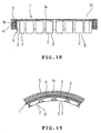
- FIGS. 18 and 19 illustrate a part of a rotor for a conventional permanent magnet motor of the outer rotor type in which a rotor is disposed around a stator.
- a rotor 10 comprises a frame 1 made from a magnetic material and including a disc-like main plate 1a and an annular circumferential wall 1b located around the main plate 1a, and a plurality of permanent magnets 2 arranged on an inner circumferential face of the wall 1b for the purpose of forming magnetic poles.
- a ring member 4 made from a magnetic material is disposed along an outer circumference of the wall 1b.
- the aforesaid frame 1, permanent magnets 2 and ring member 4 are integrally combined with one another by a synthetic resin 5.
- Japanese Patent No. 3017953 discloses a rotor with the above-described construction.
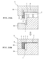
- a forming die 6 includes a lower die 6a and an upper die 6b as shown in FIG. 20A.
- the permanent magnets 2 are inserted into a recess 7 formed in the lower die 6a.
- the recess 7 is formed into an annular configuration according to a shape and the number of the permanent magnets 2.
- the frame 1 is then put over the permanent magnets 2 inserted in the recess 7, and the ring member 4 is further disposed along the outer circumference of the frame.
- the upper die 6b is put onto the lower die 6a so that the forming die 6 is closed as shown in FIG. 20B.
- a cavity 8 defined between the upper and lower dies 6b and 6a is filled with a synthetic resin 5 in the molten state.
- the synthetic resin 5 has been hardened, the upper die 6b is removed and the rotor 10 is taken from the lower die 6b.
- a number of permanent magnets 2 are integrally combined with the frame 1 by the synthetic resin in the annularly arranged state.
- the recess 7 needs to be provided in the lower die 6a in order that the permanent magnets 2 may be prevented from being displaced during filling the interior of the die 6 with the synthetic resin 5. Accordingly, the configuration of the lower die 6a is complicated.
- an object of the present invention is to provide a rotor for the permanent magnet motor of the outer rotor type which can simplify the configuration of the forming die.
- the present invention provides a rotor for a permanent magnet motor of an outer rotor type, the rotor having a plurality of permanent magnets and disposed around a stator, the rotor comprising a frame, an annular iron core combined integrally with the frame, and a plurality of insertion holes formed in the core so that the permanent magnets are inserted in the insertion holes respectively.
- the permanent magnets are inserted in the insertion holes respectively, whereby the permanent magnets are arranged annularly. Accordingly, the construction of the forming die can be simplified as compared with the conventional rotor in which the permanent magnets are positioned when disposed in the forming die.
- Each insertion hole preferably has a generally V-shaped or arc section and each insertion hole preferably has two opposite ends located at an inner circumferential side of the core, and each permanent magnet preferably has a generally V-shaped or arc section corresponding to a configuration of each insertion hole.
- magnetic fluxes passing between the permanent magnets adjacent to each other are circumferentially inclined. Accordingly, no space for formation of magnetic paths is required outside the permanent magnets in the core. Furthermore, a plastic frame may be used since the frame need not have a function of a back yoke. Accordingly, the weight of the rotor can be reduced. Additionally, since the magnetic flux flowing inside the permanent magnets in the core is concentrated to a central portion of the magnetic pole, the magnetic flux distribution is approximated to a sinusoidal waveform. Consequently, the cogging torque can be reduced.
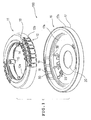
- FIG. 1 A first embodiment of the present invention will be described with reference to FIGS. 1 to 8.
- a permanent magnet motor 100 of the outer rotor type is shown.
- the motor 100 comprises a stator 11 and a rotor 16.
- the motor 100 is mounted, for example, on a rear wall of a water tub constituting a washing machine to direct drive a rotating tub.
- the stator 11 includes an annular yoke 12a and a stator core 12 having a number of teeth 12b projecting radially outward from an outer circumference of the yoke 12a.
- the stator core 12 is made, for example, by laminating a number of silicon steel sheets stamped out into a predetermined configuration.
- a covering member 14 made of an insulating resin is provided substantially over entire outer faces of the yoke 12a and teeth 12b by means of molding.
- a plurality of mounting portions 15 are provided integrally on the covering member 14 so as to be located on an inner circumference of the yoke 12a. The mounting portions 15 are used for mounting the stator 11 on a rear wall (not shown) of a water tub of a washing machine.
- the stator 11 is constructed as described above.
- the rotor 16 includes a frame 17 and a rotor core 18 both formed integrally from a synthetic resin 35 (see FIGS. 2 to 4).
- the frame 17 is made by pressing a magnetic material such as steel sheet into the shape of a bottomed flat cylinder.
- the frame 17 includes a main sheet portion 17a having a central shaft-supporting mounting hole 20 and an annular wall 17b standing at an outer circumferential edge of the main sheet portion 17a.
- a shaft support (not shown) supporting a rotational shaft is adapted to be mounted in the mounting hole 20.
- the rotational shaft is rotatably mounted on bearings (not shown).
- a stepped portion 21 is provided along an overall outer circumference of the main sheet portion 17a.
- the rotor core 18 is disposed in a space defined by the stepped portion 21 and an annular wall 17b. In this case, inner circumferential faces of the rotor core 18 and stepped portion 21 are rendered substantially coplanar.
- the stepped portion 21 has a plurality of through holes 22 formed along an overall circumference thereof.
- the main sheet portion 17a has a number of vent holes 23 which are formed in a portion thereof between the mounting hole 20 and the stepped portion 21 so as to be arranged radially about the mounting hole.
- the rotor core 18 is made by laminating a large number of sheets of annularly punched magnetic material such as steel sheets.
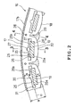
- the rotor core 18 has a number of insertion holes 25 formed therein. Permanent magnets 19 for forming magnetic poles are provided in the insertion holes 25 respectively.
- a plurality of steel sheets composing an upper end of a laminate of steel sheets have no insertion holes 25. Accordingly, the insertion holes 25 are open at a lower end of the rotor core 18 but are closed at the upper end of the rotor core.
- Each insertion hole 25 includes a rectangular narrow portion 25a extending tangentially with respect to the core 18 and a wide portion 25b.
- the wide portion 25b is located at the outer circumferential side of the core 18 and has a recess 27 formed at a central outer circumferential portion thereof and having a generally semicircular section.
- Distance B from the wide portion 25b to the outer circumference of the core 18 is set to be longer than distance A from the narrow portion 25a to an inner circumference of the core 18.
- Each permanent magnet 19 is formed into the shape of a rectangular plate and has a length that is substantially the same as a circumferential length of the narrow portion 25a.
- Each permanent magnet 19 occupies an overall narrow portion 25a and a part of the wide portion 25b. Accordingly, both circumferential ends and an outer circumferential portion of each wide portion 25b have a space where no permanent magnet 19 is located.
- the aforesaid overall narrow portion 25a and part of the wide portion 25b serve as a magnet location.
- a stepped portion 26 between the narrow and wide portions 25a and 25b serves as a positioning portion.
- Each employed permanent magnet 19 is of a high energy product type having a magnetic force not less than 2370 MA/m.
- Each permanent magnet 19 is magnetized in the direction of thickness thereof.
- the rotor core 18 has a plurality of arc convex portions 30 formed on an inner circumferential face thereof. Each arc convex portion 30 is formed so that radial dimensions thereof at both circumferential ends thereof are smaller than a radial dimension thereof at the center thereof. Each trough 29 is located at the outer circumferential side relative to a radial center O at a portion thereof where a maximum radial dimension is achieved. Furthermore, the rotor core 18 has a plurality of through holes 28 formed so as to be located at an outer circumferential side relative to the respective troughs 29 and so as to extend axially therethrough.
- a forming die comprises a lower die 32a and an upper die 32b.
- the lower die 32a includes a convex portion 33 in compliance with the shape of the rotor 16. More specifically, the rotor core 18 is disposed along an outer circumference of the convex portion 33 of the lower die 32a after the permanent magnet 19 has been inserted in the insertion hole 25.
- the frame 17 is then placed on the rotor core 18, and the upper die 32b is placed on the frame 17 so that the die is closed. Subsequently, a molten synthetic resin 35 is poured into a cavity 34 defined by the upper and lower dies 32b and 32a.
- the molten synthetic resin fills the through holes 28, the wide portions 25b of the insertion holes 25, the recesses 27 and the troughs 29. That is, the through holes 28 serve as passages for the molten resin 35. Parts of the wide portions 25b where no permanent magnets 19 are provided also serve as passages for the molten resin 35. Additionally, the molten resin 35 penetrates through the holes 22 outside the frame 17.
- the wide portion 25b and the recess 27 are filled with the molten resin 35 such that each permanent magnet 19 is put aside to the inner circumferential end face of the insertion hole 25.
- the permanent magnet 19 is positioned in the narrow portion 25a of the insertion hole 25.
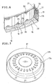
- the molten resin 35 is formed into a plurality of ribs radially extending around the mounting hole 20 of the frame 17 as shown in FIG. 5. The upper die 32b is then removed when the molten resin 35 has been hardened, and the rotor 16 is removed from the lower die 32a.
- the rotor 16 in which the frame 17, rotor core 18 and permanent magnets 19 are integrally combined together is made.
- the permanent magnets 19 are inserted in the insertion holes 25 respectively in the foregoing embodiment. Accordingly, the forming die 32 requires no recesses to position the permanent magnets 19. Consequently, since the construction of the forming die is simplified, the cost of the product can be reduced. Furthermore, the convex portions 30 are formed on the inner circumferential face of the rotor core 18, and an air gap between the rotor core 18 and the stator 1 is gradually increased from the central portion of the magnetic pole toward both circumferential ends. Accordingly, the magnetic flux density between the stator and rotor cores 12 and 18 is gradually decreased from the central portion of the magnetic pole toward both circumferential ends, whereupon the distribution of magnetic flux density is approximated to a sinusoidal waveform. Consequently, the cogging torque can be reduced and accordingly, the motor characteristics can be improved and amounts of oscillation and noise can be reduced.
- the troughs 29 are formed between the adjacent magnetic poles of the rotor core 18. Consequently, the magnetic flux flowing between the permanent magnets 19 can be prevented from shorting. In other words, the magnetic flux flowing between the permanent magnets 19 adjacent to each other can be caused to pass to the outer circumferential portion of the rotor core 18. Furthermore, the synthetic resin 35 fills the through holes 28 and the troughs 29. Accordingly, the frame 17, the rotor core 18 and the permanent magnets 19 are combined together more firmly. Moreover, the through holes 28 are formed in the outer circumferential side of the core 18. Accordingly, the flow of magnetic flux from the permanent magnets 19 to the stator 11 is not blocked and a reduction in the motor characteristics due to provision of the through holes 28 can be prevented.
- the distance B from each insertion hole 25 to the outer circumference of the core 18 is set to be longer than the distance A from each insertion hole 25 to the outer circumference of the core 18. Consequently, a sufficient passage for the magnetic flux can be ensured in the outer circumference of the core 18 and accordingly, the flow of magnetic flux between the adjacent permanent magnets 19 can be improved.
- FIG. 9 illustrates a second embodiment of the invention. Only the difference of the second embodiment from the previous one will be described. Identical or similar parts in the second embodiment are labeled by the same reference symbols as those in the first embodiment, and the description of these parts will be eliminated.
- the rotor core 18 comprises a plurality of unit cores 18a connected one to another into an annular configuration.
- the magnetic force is reduced since the magnetic resistance is increased at connected portions 41 of each unit core 18a. Accordingly, the rotational speed of the rotor 16 is reduced near the connected portions 41 in the construction of feedback control of the motor. A current value and a voltage value are increased so that the rotational speed of the rotor is increased. Thus, in the above-described arrangement, a rotational position of the rotor 16 can be detected by measuring the current and voltage values. Additionally, a material for the core 18 can efficiently be used.
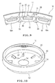
- FIGS. 10 to 14 illustrate a third embodiment of the invention. Only the difference of the third embodiment from the first embodiment will be described.
- the rotor 16 of the second embodiment includes a frame 52 and a rotor core 53 both integrated by molding.
- the frame 52 is made by pressing a magnetic material such as a steel sheet into the shape of a bottomed flat cylinder.
- the frame 52 includes a main sheet portion 55 having a central shaft-supporting mounting hole 54 and an annular wall 56 standing at an outer circumferential edge of the main sheet portion 55.
- a stepped portion 57 is provided along an overall outer circumference of the main sheet portion 55.
- the rotor core 53 is disposed in a space defined by the stepped portion 57 and an annular wall 56. In this case, inner circumferential faces of the rotor core 53 and stepped portion 57 are rendered substantially coplanar.
- the stepped portion 57 has a plurality of through holes 58 formed along an overall circumference thereof.
- the main sheet portion 55 has a number of vent holes 55a which are formed in a portion near the inner circumference thereof by cutting and raising so as to be arranged radially about the mounting hole 12.
- the rotor core 53 is made by laminating a large number of sheets of annularly punched magnetic material such as steel sheets.
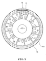
- the rotor core 53 has a number of generally V-shaped insertion holes 59 formed therein. Pairs of permanent magnets 60 for forming magnetic poles are provided in the insertion holes 59 respectively. Each pair of permanent magnets 60 constitute magnetic poles in the embodiment.
- Each insertion hole 59 has a central bent portion located at the outer circumferential side of the rotor core 53 and both circumferential ends located at the inner circumferential side of the rotor core. Each insertion hole 59 is open at the outer circumferential face of the rotor core 53. Of the laminated steel sheets composing the rotor core 53, one or a plurality of steel sheets located at both axial ends have no insertion holes 59. Accordingly, both axial ends of each insertion hole 59 are closed.
- Each permanent magnet 60 has the shape of a rectangular flat plate.
- Each pair of permanent magnets 60 are contained in a storage section 59a extending from the bent portion to one end of the insertion hole 59 and a storage section 59b extending from the bent portion to the other end of the insertion hole respectively.
- Each storage section 59a or 59b has a recess 61 formed in a central outer periphery so as to extend full axial length of the rotor core 53 and having a generally semicircular section.
- the permanent magnets 60 are inserted through an opening 59c of each insertion hole 59 into the storage sections 59a and 59b at the outer circumferential face of the rotor core 53 respectively. In this case, the recesses 61 are not occupied by the permanent magnets 60 and accordingly serve as spaces.
- Each employed permanent magnet 60 is of a high energy product type having a magnetic force not less than 316 MA/m. Each permanent magnet 60 is magnetized in the direction of thickness thereof. Each pair of magnets 60 are contained in the storage sections 59a and 59b so that inner circumferential side faces thereof have the same polarity. Furthermore, the rotor core 53 has axially extending circular through holes 62 located between the insertion holes 59 adjacent to each other. The rotor core 53 further has semicircular notches 63 which are formed in the outer circumferential face thereof so as to be located between the insertion holes 59 adjacent to each other.
- molten resin 35 is poured into the space between the annular wall 56 and stepped portion 57 of the frame 52 and the rotor core 53 and hardened so that the frame and the rotor core are integrated.
- the synthetic resin 35 flows through the holes 58 to be located outside the frame 52.
- the molten resin 35 also fills the through holes 62 and the notches 63.
- the rotor core 53 is firmly fixed to the frame 52.
- the molten resin 35 further flows through the openings 59c into the insertion holes 59, whereupon the permanent magnets 60 are pushed against the inner peripheral ends of the storage sections 59a and 59b thereby to be positioned.
- the resin 35 having flown into each insertion hole 59 further flows through gaps between the permanent magnets 60 and the storage sections 59a and 59b into the recesses 61, whereupon the permanent magnets 60 are pushed against the inner faces of the storage sections 59a and 59b located opposite the recesses 61 respectively thereby to be positioned.
- a portion of each storage section 59a or 59b except a portion filled with the resin 35 serves as a magnet disposing portion.
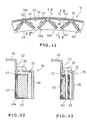
- FIG. 14 illustrating magnetic flux emerging from and re-entering the permanent magnets 60.
- the inner circumferential side (stator side) of the rotor core 53 is shown as the lower side as viewed in FIG. 13.
- the direction of magnetic flux ⁇ emerging from and re-entering the permanent magnets 60 is inclined circumferentially.
- the thickness of the annular wall 56 is enough to ensure the mechanical strength required to support the rotor core 53.
- the thickness of the annular wall 56 can be reduced as compared with the prior art and accordingly, the weight of the rotor can be reduced.
- magnetic flux ⁇ flowing in the inner circumferential side of the rotor core 53 relative to the permanent magnets 60 is directed to the central magnetic pole. Accordingly, the magnetic flux density becomes higher in the central portion than in the ends. Consequently, since the magnetic flux density distribution in a core gap approximates to a sinusoidal waveform, the motor characteristics can be improved with reduction in the cogging torque.
- the V-shaped insertion holes 59 are formed in the rotor core 53, and two permanent magnets 60 constituting the magnetic poles are contained in each insertion hole 59.
- the magnetic direction of each magnet 60 is inclined circumferentially. Accordingly, since the annular wall 56 of the frame 52 need not serve as a back yoke, the thickness of the annular wall 56 can be reduced accordingly.
- two permanent magnets 60 are contained in the storage section 59a at one circumferential side and the storage section 59b at the other circumferential side of each insertion hole 59 respectively. Accordingly, no permanent magnet is located at a circumferentially central portion of each insertion hole 59 where the magnetic direction is radial. Consequently, the thickness of the frame 52 can further be reduced.
- a radial dimension of the rotor core 53 could be reduced by employment of an anisotropic permanent magnet (plastic magnet) in which the magnetic direction is a circumferential direction.
- an anisotropic permanent magnet plastic magnet
- the production cost of an anisotropic permanent magnet is disadvantageously high.
- the ordinary rectangular permanent magnets 60 are employed and accordingly, an increase in the production cost can be prevented.
- the rotor core 53 comprises a laminated iron core. Consequently, energy loss can be reduced.
- the frame 52 and the rotor core 53 are integrated by the synthetic resin 35.
- the through holes 62 and the notches 63 are formed in the rotor core 53 in the embodiment. These holes 62 and notches 63 are filled with the synthetic resin 35.
- the frame 52 and the rotor core 53 can be integrated firmly.
- the through holes 62 and the notches 63 are located at the outer circumferential side relative to the permanent magnets 60, the motor characteristics can be prevented from being adversely affected.
- each insertion hole 59 is open at the outer circumferential face of the rotor core 53, whereas the upper and lower ends of each insertion hole 59 are closed. Consequently, each permanent magnet can be prevented from being axially moved.
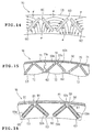
- FIG. 15 illustrates a fourth embodiment of the invention. Only the difference of the fourth embodiment from the third embodiment will be described.
- the rotor core 53 comprises a plurality of unit cores 71 which are connected into an annular configuration. Each unit core 71 corresponds to a divided part of the core 53 including a plurality of magnetic poles.
- the unit cores 71 are connected to one another so that a connection 71a of the adjacent unit cores 71 is located between the magnetic poles as shown in FIG. 15. Consequently, the material for the core 53 can efficiently be used. Moreover, since the connection 71a is located between the magnetic poles, the magnetic flux density distribution can be prevented from being adversely affected.
- the rotor core 53 has a plurality of arc convex portions 30 formed on an inner circumferential face thereof except both circumferential ends of each magnetic pole.
- Each arc convex portion 72 is formed so that radial dimensions thereof at both circumferential ends thereof are smaller than a radial dimension thereof at the center thereof.
- the configuration, arrangement and dimensions of each convex portion 72 are set so that the air-gap magnetic flux density distribution is rendered substantially sinusoidal.
- the configuration, arrangement and dimensions of each convex portion 72 were obtained from experiments carried out by the inventors. The above-described construction can improve the motor characteristics.
- each storage section 59a and 59b has a width substantially equal to or smaller than the thickness of the permanent magnet 60, and the permanent magnets 60 are fitted into the storage sections 59a and 59b. Accordingly, no recesses 61 are formed in the outer periphery of each storage section 59a and 59b in the embodiment.
- the rotor core 53 has no through holes 62 and no notches 63 in the embodiment. When the frame 52 and the rotor core 53 are integrated, the synthetic resin 35 fills each section of the inner circumferential face of the rotor core 53 between adjacent convex portions 72. Accordingly, the rotor core 53 can be fixed to the frame 52 firmly even when the through holes 62 and the notches 63 are eliminated.
- the inner circumferential face of the rotor core 53 can be smoothed since the synthetic resin 35 fills each section of the inner circumferential face of the rotor core 53 between adjacent convex portions 72. Accordingly, an increase in the noise due to rotation of the rotor 51 can be prevented by provision of the convex portions 72 on the inner circumferential face of the core 53.
- FIG. 16 illustrates a fifth embodiment of the invention. Only the difference of the fifth embodiment from the first embodiment will be described.
- protrusions 81 are provided near the opening 59c of each insertion hole 59 so as to correspond to the storage sections 59a and 59b respectively.
- the protrusions 81 protrude to the outer circumferential side before insertion of the permanent magnets into the respective storage sections 59a and 59b.
- the protrusions 81 are bent thereby to depress the permanent magnets 60 to the inner circumferential side. In this construction, too, the permanent magnets 60 can be positioned in the respective storage sections 59a and 59b.
- Each permanent magnet 60 is formed into the rectangular plate shape in the foregoing embodiments.
- a plurality of permanent magnets 91 each formed into the shape of a generally arc plate may be used, instead.
- each one permanent magnet 91 establishes one magnetic pole.
- the thickness of the frame 52 can be reduced since the magnetic direction of each permanent magnet 51 is inclined circumferentially.
- the frame need not be provided with a function as the back yoke. Accordingly, the frame may be made of plastic. Consequently, the weight of the rotor can further be reduced.
- a rotor for a permanent magnet motor of an outer rotor type in accordance with the present invention is useful as a large rotor having a number of permanent magnets for forming magnetic poles and suitable for use in an electric motor directly driving a rotating tub of a washing machine, for example.
Landscapes
- Engineering & Computer Science (AREA)
- Power Engineering (AREA)
- Manufacturing & Machinery (AREA)
- Permanent Field Magnets Of Synchronous Machinery (AREA)
Abstract
Description
Additionally, a material for the core 18 can efficiently be used.
Claims (19)
- A rotor for a permanent magnet motor of an outer rotor type, the rotor having a plurality of permanent magnets and disposed around a stator, the rotor comprising:a frame (17, 52);an annular iron core (18, 53) combined integrally with the frame (17, 52); anda plurality of insertion holes (25, 59) formed in the core (18, 53) so that the permanent magnets are inserted in the insertion holes (25, 59) respectively.
- A rotor according to claim 1, wherein the core (18, 53) includes magnetic poles having respective inner circumferential faces, and the core is arranged so that a distance between the stator (11) and the inner circumferential face of each magnetic pole is non-uniform with respect to a circumferential direction.
- A rotor according to claim 2, wherein the inner circumferential face of each magnetic pole of the core (18) has two opposite ends having respective distances between the opposite ends and the stator (11), said distances between each opposite end and the stator core (18) is shorter than a distance between a circumferentially central portion of the inner circumferential face and the stator (18).
- A rotor according to claim 1, wherein the core includes a plurality of trough portions (29) provided between respective insertion holes adjacent to each other in the inner circumferential portion thereof, and a distance between an outer circumferential end of each trough (29) and an outer circumferential portion of the core (18) is smaller than a distance between a radial center of the core (18) and the outer circumferential end of the core (18).
- A rotor according to claim 1, wherein each insertion hole has a generally V-shaped or arc section with respect to a direction perpendicular to a radial direction and each insertion hole (59) has two opposite ends located at an inner circumferential side of the core (53), and each permanent magnet (60, 91) has a generally V-shaped or arc section corresponding to a configuration of each insertion hole (59).
- A rotor according to claim 1, wherein each insertion hole has a generally V-shaped or arc section with respect to a direction perpendicular to a radial direction and each insertion hole (59) has two opposite ends located at an inner circumferential side of the core (53), and the core (53) has a plurality of magnetic poles each of which is composed of two permanent magnets (60) provided in a circumferential one side of each insertion hole (59) and the other side of each insertion hole (59) respectively.
- A rotor according to claim 6, wherein each permanent magnet (60) is formed into a shape of a generally flat plate.
- A rotor according to claim 6, wherein the frame (52) includes an annular wall (56) extending along an outer circumferential face of the core (53), and each insertion hole (59) is open at the outer circumferential face of the core (53).
- A rotor according to claim 1, wherein the frame (17, 52), the core (18, 53) and the permanent magnets (19, 60) are combined integrally with each other by a synthetic resin (35), and the core (18, 53) has a through hole (28, 62) from which a molten synthetic resin is poured.
- A rotor according to claim 9, wherein a distance from the through hole (28) to the outer circumference of the core (18) is shorter than a distance from an axial center in a portion of the core (18) where the core (18) has a maximum axial dimension, to the outer circumference of the core (18).
- A rotor according to claim 9, wherein the through hole (28, 62) is formed nearer to the outer circumference of the core (18, 53) than the permanent magnets (19, 60) in the core (18, 53).
- A rotor according to claim 9, wherein the through hole (28, 62) is formed in the core (18, 53) so as to be located between the magnetic poles.
- A rotor according to claim 1, wherein the frame (17), the core (18) and the permanent magnets (19) are combined integrally with one another by a synthetic resin (35), and each insertion hole (25) includes a magnet disposing portion (25a, 25b) in which the permanent magnet (19) is disposed, a space portion (25b) located in at least one of circumferential both ends of each permanent magnet (19) disposed in the magnet disposing portion (25a, 25b), and a positioning portion (26) positioning each permanent magnet (19) in the magnet disposing portion (25a, 25b), and the molten synthetic resin is poured into the space portion (25b).
- A rotor according to claim 1, wherein the frame (17, 52), the core (18, 53) and the permanent magnets (19, 60) are combined integrally with each other by a synthetic resin (35), and each insertion hole (25, 59) includes a magnet disposing portion (25a, 25b, 59a, 59b) in which the permanent magnet (19, 60) is disposed and a recess(27, 61) defining a space along an outer periphery of each permanent magnet (19, 60) disposed in the magnet disposing portion, and the molten synthetic resin (35)is poured into the recess (27, 61).
- A rotor according to claim 1, wherein a distance from an outer circumferential portion of the core (18) to each insertion hole (25) is longer than a distance from an inner circumferential portion of the core (18) to each insertion hole (25).
- A rotor according to claim 1, wherein the core (18, 53) includes a plurality of unit cores (18a, 71) disposed into an annular form.
- A rotor according to claim 1, wherein the core includes a plurality of steel sheets laminated.
- A rotor according to claim 1, wherein the permanent magnets are fitted in the insertion holes respectively.
- A rotor according to claim 1, wherein each insertion hole has both axial ends, and either one of the axial ends of each insertion hole is closed.
Applications Claiming Priority (5)
| Application Number | Priority Date | Filing Date | Title |
|---|---|---|---|
| JP2002179785 | 2002-06-20 | ||
| JP2002179785A JP4490621B2 (en) | 2002-06-20 | 2002-06-20 | Rotor of abduction type permanent magnet motor |
| JP2002310967 | 2002-10-25 | ||
| JP2002310967A JP3725510B2 (en) | 2002-10-25 | 2002-10-25 | Rotor of abduction type permanent magnet motor |
| PCT/JP2003/007631 WO2004001930A1 (en) | 2002-06-20 | 2003-06-16 | Rotor for external rotor-type permanent magnet motor |
Publications (3)
| Publication Number | Publication Date |
|---|---|
| EP1536543A1 true EP1536543A1 (en) | 2005-06-01 |
| EP1536543A4 EP1536543A4 (en) | 2006-04-26 |
| EP1536543B1 EP1536543B1 (en) | 2013-03-13 |
Family
ID=30002247
Family Applications (1)
| Application Number | Title | Priority Date | Filing Date |
|---|---|---|---|
| EP03733455A Expired - Lifetime EP1536543B1 (en) | 2002-06-20 | 2003-06-16 | Rotor for external rotor-type permanent magnet motor |
Country Status (4)
| Country | Link |
|---|---|
| US (1) | US7262526B2 (en) |
| EP (1) | EP1536543B1 (en) |
| NZ (1) | NZ537718A (en) |
| WO (1) | WO2004001930A1 (en) |
Cited By (19)
| Publication number | Priority date | Publication date | Assignee | Title |
|---|---|---|---|---|
| FR2890250A1 (en) * | 2005-08-30 | 2007-03-02 | Aisin Seiki | LAMINATE CORE OF ROTATING ELECTRIC MACHINE. |
| DE102007007823A1 (en) * | 2007-02-16 | 2008-08-21 | Siemens Ag | Secondary part formed as rotor of a rotatory electrical machine, comprises permanent magnets, bags for the reception of the permanent magnets, and cavity present between the bag and the permanent magnet |
| DE102008017276A1 (en) | 2008-04-04 | 2009-10-15 | Danfoss Compressors Gmbh | Rotor for an electric drive motor of a refrigerant compressor |
| EP1777795A3 (en) * | 2005-10-24 | 2010-01-20 | General Electric Company | Permanent magnet pole assembly |
| US7653984B2 (en) | 2006-01-11 | 2010-02-02 | Mitsui High-Tec, Inc. | Method of resin sealing permanent magnets in laminated rotor core |
| US7692349B2 (en) | 2006-02-15 | 2010-04-06 | Lg Electronics Inc. | Direct drive motor for washing machine and method of manufacturing the same |
| EP1903665A3 (en) * | 2006-09-20 | 2011-02-16 | VENSYS Energy AG | A method for fastening permanent magnet magnetic poles to the rotor of an electric machine |
| US7897089B2 (en) * | 2005-01-24 | 2011-03-01 | Mitsui High-Tec, Inc. | Method of resin sealing permanent magnets in laminated rotor core |
| US7948138B2 (en) | 2005-04-28 | 2011-05-24 | Toyota Jidosha Kabushiki Kaisha | Rotor |
| US7987579B2 (en) | 2009-03-21 | 2011-08-02 | Vensys Energy Ag | Method for mounting permanent magnets that form magnetic poles on the rotor of an electric machine |
| US8020280B2 (en) | 2006-02-08 | 2011-09-20 | Toyota Jidosha Kabushiki Kaisha | Rotor manufacturing method |
| WO2011006810A3 (en) * | 2009-07-13 | 2011-10-27 | Siemens Aktiengesellschaft | Annular rotor for an electric machine |
| EP2587644A3 (en) * | 2011-10-26 | 2013-09-11 | Whirlpool Corporation | Method of manufacturing a rotor for an electric motor for a washing machine |
| EP2817868A1 (en) * | 2012-02-20 | 2014-12-31 | Moteurs Leroy-Somer | Rotor of a rotating machine with flux concentration |
| US9003639B2 (en) | 2006-02-27 | 2015-04-14 | Toyota Jidosha Kabushiki Kaisha | Method of manufacturing a rotor |
| CN104767304A (en) * | 2014-01-08 | 2015-07-08 | 普罗蒂恩电子有限公司 | A rotor for an electric motor or generator |
| US20150214796A1 (en) * | 2014-01-27 | 2015-07-30 | Delta Electronics, Inc. | Magnet module and fan with magnet module |
| EP3896824A4 (en) * | 2019-01-10 | 2022-11-30 | Johnson Electric International AG | Magnetic core, electric motor having magnetic core, and mower having electric motor |
| WO2022258380A3 (en) * | 2021-06-10 | 2023-02-23 | Wobben Properties Gmbh | Rotor segment, magnet cover, rotor, generator, wind turbine and molding device and method for producing a rotor segment |
Families Citing this family (76)
| Publication number | Priority date | Publication date | Assignee | Title |
|---|---|---|---|---|
| JP3725510B2 (en) * | 2002-10-25 | 2005-12-14 | 株式会社東芝 | Rotor of abduction type permanent magnet motor |
| JP4599088B2 (en) | 2004-05-13 | 2010-12-15 | 東芝コンシューマエレクトロニクス・ホールディングス株式会社 | Rotor for rotating electrical machine and method for manufacturing the same |
| JP4550496B2 (en) * | 2004-06-28 | 2010-09-22 | 株式会社東芝 | Electric motor rotor |
| KR20060031277A (en) * | 2004-10-08 | 2006-04-12 | 주식회사 대우일렉트로닉스 | Rotor braid of outer rotor type motor |
| US7342334B2 (en) * | 2004-10-29 | 2008-03-11 | Emerson Electric Co. | Insulated stator with wire routing element |
| US7385328B2 (en) | 2006-05-23 | 2008-06-10 | Reliance Electric Technologies, Llc | Cogging reduction in permanent magnet machines |
| JP2008245405A (en) * | 2007-03-27 | 2008-10-09 | Aisin Seiki Co Ltd | Rotor and method for manufacturing the same |
| US20080238234A1 (en) * | 2007-03-27 | 2008-10-02 | Hamilton Sundstrand Corporation | Segmented permanent magnet rotor for high speed synchronous machines |
| JP4466681B2 (en) * | 2007-05-11 | 2010-05-26 | トヨタ自動車株式会社 | Rotating electric machine rotor and rotating electric machine |
| US7687959B1 (en) | 2007-12-17 | 2010-03-30 | Lee S Peter | Brushless a-c motor |
| JP4605481B2 (en) * | 2008-07-07 | 2011-01-05 | 本田技研工業株式会社 | Permanent magnet rotor |
| JP4403253B1 (en) * | 2009-01-14 | 2010-01-27 | 有限会社クラ技術研究所 | Magnetic flux amount variable axial gap rotating electrical machine system |
| WO2011030536A1 (en) * | 2009-09-10 | 2011-03-17 | パナソニック株式会社 | Electric motor and electric device provided therewith |
| JP5493663B2 (en) * | 2009-10-01 | 2014-05-14 | 信越化学工業株式会社 | Assembling method of rotor for IPM type permanent magnet rotating machine |
| IT1397783B1 (en) * | 2010-01-15 | 2013-01-24 | Gate Srl | PERMANENT MAGNET ROTOR FOR A BRUSHLESS MOTOR IN DIRECT CURRENT |
| US8405268B2 (en) | 2010-02-18 | 2013-03-26 | Nidec Motor Corporation | Stator with monolithic mounting bosses and assembly comprising the same |
| US9013074B2 (en) | 2010-05-25 | 2015-04-21 | Regal Beloit America, Inc. | Resilient rotor assembly for interior permanent magnet motor |
| AU2015202559B2 (en) * | 2010-06-25 | 2016-06-16 | Fisher & Paykel Appliances Limited | A rotor for a motor, and a motor and an appliance comprising the rotor, and a method for making a rotor |
| WO2011162624A1 (en) * | 2010-06-25 | 2011-12-29 | Fisher & Paykel Appliances Limited | A rotor for a motor, and a motor and an appliance comprising the rotor, and a method for making a rotor |
| DE102010051264A1 (en) * | 2010-11-12 | 2012-05-16 | Secop Gmbh | Method for manufacturing rotor of external rotor motor, involves connecting base portion in such a manner with cylinder ring that the aperture is concentrically aligned to peripheral surface of cylindrical die |
| US8760015B2 (en) * | 2011-02-18 | 2014-06-24 | Hamilton Sundstrand Corporation | Cooling of permanent magnet electric machine |
| KR101243491B1 (en) * | 2011-04-13 | 2013-03-13 | 뉴모텍(주) | Rotor for Motor |
| US20140091663A1 (en) * | 2011-05-16 | 2014-04-03 | Mitsubishi Electric Corporation | Permanent-magnet type rotating electrical machine |
| JP5536151B2 (en) * | 2011-08-25 | 2014-07-02 | ファナック株式会社 | Manufacturing method of magnet plate for linear motor |
| KR101900456B1 (en) * | 2011-09-08 | 2018-09-21 | 삼성전자주식회사 | Motor and washing machine having the same |
| US8941274B2 (en) * | 2012-03-23 | 2015-01-27 | Whirlpool Corporation | Stator for an electric motor of a washing machine and method of manufacturing the same |
| JP5786804B2 (en) | 2012-06-13 | 2015-09-30 | 株式会社デンソー | Rotor for rotating electrical machine and method for manufacturing the same |
| KR101407854B1 (en) * | 2012-12-03 | 2014-06-16 | 뉴모텍(주) | Motor with Variable Magnet Flux |
| JP5904293B2 (en) * | 2013-02-08 | 2016-04-13 | 富士電機株式会社 | Permanent magnet embedded rotary electric machine |
| JP5892106B2 (en) * | 2013-04-15 | 2016-03-23 | 株式会社安川電機 | Rotating electric machine and method of manufacturing rotor |
| US10027192B2 (en) * | 2013-06-12 | 2018-07-17 | Mitsubishi Electric Corporation | Motor with permanent magnet embedded therein, and compressor |
| KR102073005B1 (en) * | 2013-07-17 | 2020-02-04 | 삼성전자주식회사 | Motor |
| JP2015104244A (en) * | 2013-11-26 | 2015-06-04 | ファナック株式会社 | Rotor having resin hole for filling resin, and method of manufacturing rotor |
| US9985485B2 (en) * | 2014-04-01 | 2018-05-29 | GM Global Technology Operations LLC | Magnet insert design for rotor lamination |
| TWI530067B (en) * | 2014-05-21 | 2016-04-11 | 建準電機工業股份有限公司 | Ceiling fan motor |
| CA2962084A1 (en) * | 2014-09-24 | 2016-03-31 | Tm4 Inc. | Reluctance assisted external rotor pmsm |
| US10333362B2 (en) | 2014-10-15 | 2019-06-25 | Accelerated Systmes Inc. | Internal permanent magnet motor with an outer rotor |
| JP6359116B2 (en) * | 2014-11-10 | 2018-07-18 | 三菱電機株式会社 | Rotating electric machine |
| JP6382085B2 (en) * | 2014-11-28 | 2018-08-29 | 日立オートモティブシステムズ株式会社 | Rotating electric machine rotor and rotating electric machine using the same |
| JP6206438B2 (en) * | 2015-04-01 | 2017-10-04 | トヨタ自動車株式会社 | Laminated rotor and manufacturing method thereof |
| DE102015206100A1 (en) * | 2015-04-02 | 2016-10-06 | Bühler Motor GmbH | Permanent magnet rotor |
| KR102331602B1 (en) * | 2015-04-06 | 2021-11-30 | 엘지전자 주식회사 | Laundry Treating Apparatus |
| JP6480789B2 (en) * | 2015-04-13 | 2019-03-13 | 本田技研工業株式会社 | Rotating electrical machine rotor |
| DE102016116883A1 (en) * | 2015-09-11 | 2017-03-16 | Johnson Electric S.A. | Permanent magnet motor and power tool using the same |
| GB2545627B (en) * | 2015-10-16 | 2021-04-21 | Yasa Ltd | Axial flux machine arrangement |
| DE112017000602T5 (en) * | 2016-03-31 | 2018-12-13 | Aisin Aw Co., Ltd. | ROTOR FOR A TURNING ELECTRIC MACHINE |
| US11043863B2 (en) | 2016-03-31 | 2021-06-22 | Aisin Aw Co., Ltd. | Rotor manufacturing method |
| JP6410776B2 (en) * | 2016-10-06 | 2018-10-24 | 本田技研工業株式会社 | Rotor manufacturing method |
| US20180205302A1 (en) * | 2017-01-19 | 2018-07-19 | Hamilton Sundstrand Corporation | Permanent magnet (pm) brushless machine with outer rotor |
| WO2018158604A1 (en) * | 2017-03-03 | 2018-09-07 | Ge Renewable Technologies | Salient pole machine |
| JP2020096396A (en) * | 2017-03-30 | 2020-06-18 | 日本電産テクノモータ株式会社 | Rotor and motor with the same |
| FR3064837B1 (en) * | 2017-04-03 | 2020-01-17 | Moving Magnet Technologies | ROTOR FOR ELECTRIC MACHINE WITH INTERNAL PERMANENT MAGNETS |
| CN113972806B (en) | 2017-07-21 | 2023-10-31 | 株式会社电装 | Rotary electric machine |
| JP6939750B2 (en) | 2017-12-28 | 2021-09-22 | 株式会社デンソー | Rotating machine |
| DE112018006694T5 (en) | 2017-12-28 | 2020-09-10 | Denso Corporation | Rotating electric machine |
| JP6922868B2 (en) | 2017-12-28 | 2021-08-18 | 株式会社デンソー | Rotating electrical system |
| DE112018006699T5 (en) | 2017-12-28 | 2020-09-10 | Denso Corporation | Rotating electric machine |
| EP3783773B1 (en) * | 2018-06-20 | 2023-04-12 | Guangdong Meizhi Compressor Co., Ltd. | Rotor, motor and compressor |
| JP2020054173A (en) * | 2018-09-28 | 2020-04-02 | 日本電産サーボ株式会社 | motor |
| KR102138339B1 (en) * | 2018-10-24 | 2020-07-27 | 주식회사 엠플러스 | Sound vibration actuator |
| DE102018127127B4 (en) * | 2018-10-30 | 2020-08-06 | Feaam Gmbh | Electrical machine |
| JP7522535B2 (en) * | 2019-03-20 | 2024-07-25 | 株式会社デンソー | Rotating Electric Machine |
| WO2021000184A1 (en) * | 2019-06-30 | 2021-01-07 | 瑞声声学科技(深圳)有限公司 | Vibration motor |
| JP7415360B2 (en) * | 2019-07-31 | 2024-01-17 | ニデック株式会社 | motor |
| US11289985B2 (en) * | 2019-08-09 | 2022-03-29 | Hamilton Sundstrand Corporation | Dual stator machine with a rotor magnet set configured to minimize flux leakage |
| US11264850B2 (en) * | 2019-09-05 | 2022-03-01 | Nidec Motor Corporation | Laminated rotor having deflecting magnet retaining prongs and support posts for the prongs |
| KR102696292B1 (en) * | 2020-01-08 | 2024-08-20 | 엘지마그나 이파워트레인 주식회사 | Stator ofelectric rotation machine |
| DE112020006839T5 (en) | 2020-03-05 | 2022-12-15 | Denso Corporation | Rotating electrical machines |
| JP7127082B2 (en) * | 2020-04-17 | 2022-08-29 | シナノケンシ株式会社 | Outer rotor type motor with power transmission unit |
| JP7054718B2 (en) * | 2020-04-17 | 2022-04-14 | シナノケンシ株式会社 | Outer rotor type motor |
| WO2022058939A1 (en) * | 2020-09-21 | 2022-03-24 | Evr Motors Ltd. | Radial flux electric machine |
| JP6993602B1 (en) | 2020-09-25 | 2022-01-13 | ダイキン工業株式会社 | Motors, blowers, and air conditioners |
| US11641151B2 (en) * | 2021-05-11 | 2023-05-02 | Aac Microtech (Changzhou) Co., Ltd. | Linear vibration motor with elastic members with brackets, foams and damping glue |
| TWI849682B (en) | 2023-01-09 | 2024-07-21 | 財團法人工業技術研究院 | Electric motor with double stators |
| JP2025019387A (en) * | 2023-07-28 | 2025-02-07 | ニデック株式会社 | Rotor, motor, and method for manufacturing rotor |
| US12564989B2 (en) * | 2024-04-25 | 2026-03-03 | Kuka Systems North America Llc | Transfer molding system and methods |
Family Cites Families (19)
| Publication number | Priority date | Publication date | Assignee | Title |
|---|---|---|---|---|
| DE1093000B (en) | 1956-03-23 | 1960-11-17 | Wipac Dev Ltd | Flywheel runner for electric generators with several permanent magnets |
| DE4418454A1 (en) | 1994-05-26 | 1995-11-30 | Siemens Ag | Synchronous machine external rotor design |
| JP3363682B2 (en) * | 1995-12-19 | 2003-01-08 | 株式会社ミツバ | Magnet generator |
| US5920139A (en) * | 1996-03-31 | 1999-07-06 | Sanyo Electric Co. Ltd. | Magnet motor stator |
| JP3017953B2 (en) | 1996-07-24 | 2000-03-13 | 株式会社東芝 | Motor rotor and method of manufacturing the same |
| KR100252393B1 (en) * | 1997-05-13 | 2000-04-15 | 윤종용 | Structure of reclaimed magnet type rotor |
| JP3906882B2 (en) * | 1997-10-24 | 2007-04-18 | 株式会社富士通ゼネラル | Permanent magnet motor |
| JP3524376B2 (en) * | 1998-03-31 | 2004-05-10 | 株式会社東芝 | Dehydration combined washing machine |
| JP3688898B2 (en) * | 1998-08-21 | 2005-08-31 | 株式会社東芝 | Electric motor rotor |
| JP3777839B2 (en) | 1998-11-30 | 2006-05-24 | 日亜化学工業株式会社 | Permanent magnet embedded motor |
| ES2301228T3 (en) * | 1999-01-08 | 2008-06-16 | Lg Electronics Inc. | ROTOR STRUCTURE FOR A MOTOR WITHOUT TYPE BRUSHES WITH EXTERNAL ROTOR. |
| US6492756B1 (en) * | 2000-04-05 | 2002-12-10 | Wavecrest Laboratories, Llc | Rotary electric motor having magnetically isolated stator and rotor groups |
| JP2002010602A (en) | 2000-06-19 | 2002-01-11 | Toshiba Digital Media Engineering Corp | Permanent magnet type motor and elevator device |
| JP2002112475A (en) | 2000-09-26 | 2002-04-12 | Hitachi Ltd | Permanent magnet type rotating electric machine, air compressor and generator using the same |
| JP3906022B2 (en) * | 2000-10-24 | 2007-04-18 | 株式会社東芝 | Electric motor rotor and method of manufacturing the same |
| JP3790665B2 (en) * | 2000-10-31 | 2006-06-28 | 株式会社日立製作所 | Permanent magnet rotating electric machine and electric vehicle using permanent magnet rotating electric machine |
| JP4163953B2 (en) * | 2000-12-22 | 2008-10-08 | 株式会社ミツバ | Rotor magnet holding structure |
| JP2002233122A (en) | 2001-02-05 | 2002-08-16 | Matsushita Electric Ind Co Ltd | Outer rotor motor, method of manufacturing outer rotor motor, and electric vehicle incorporating outer rotor motor |
| US6727632B2 (en) * | 2001-11-27 | 2004-04-27 | Denso Corporation | Flat rotary electric machine |
-
2003
- 2003-06-16 EP EP03733455A patent/EP1536543B1/en not_active Expired - Lifetime
- 2003-06-16 WO PCT/JP2003/007631 patent/WO2004001930A1/en not_active Ceased
- 2003-06-16 US US10/518,367 patent/US7262526B2/en not_active Expired - Fee Related
- 2003-06-16 NZ NZ537718A patent/NZ537718A/en not_active IP Right Cessation
Cited By (33)
| Publication number | Priority date | Publication date | Assignee | Title |
|---|---|---|---|---|
| US7897089B2 (en) * | 2005-01-24 | 2011-03-01 | Mitsui High-Tec, Inc. | Method of resin sealing permanent magnets in laminated rotor core |
| US10498203B2 (en) | 2005-01-24 | 2019-12-03 | Mitsui High-Tec, Inc. | Method of resin sealing permanent magnets in laminated rotor core |
| US20140151926A1 (en) * | 2005-01-24 | 2014-06-05 | Mitsui High-Tec, Inc. | Method of resin sealing permanent magnets in laminated rotor core |
| US8268219B2 (en) | 2005-01-24 | 2012-09-18 | Mitsui High-Tec, Inc. | Method of resin sealing permanent magnets in laminated rotor core |
| US8728375B2 (en) | 2005-01-24 | 2014-05-20 | Mitsui High-Tec, Inc. | Method of resin sealing permanent magnets in laminated rotor core |
| US7948138B2 (en) | 2005-04-28 | 2011-05-24 | Toyota Jidosha Kabushiki Kaisha | Rotor |
| FR2890250A1 (en) * | 2005-08-30 | 2007-03-02 | Aisin Seiki | LAMINATE CORE OF ROTATING ELECTRIC MACHINE. |
| EP1777795A3 (en) * | 2005-10-24 | 2010-01-20 | General Electric Company | Permanent magnet pole assembly |
| CN1956293B (en) * | 2005-10-24 | 2011-11-16 | 通用电气公司 | Method and apparatus for assembling a permanent magnet pole assembly |
| US7653984B2 (en) | 2006-01-11 | 2010-02-02 | Mitsui High-Tec, Inc. | Method of resin sealing permanent magnets in laminated rotor core |
| US7950133B2 (en) | 2006-01-11 | 2011-05-31 | Mitsui High-Tec, Inc. | Method of resin sealing permanent magnets in laminated rotor core |
| US8127431B2 (en) | 2006-01-11 | 2012-03-06 | Mitsui High-Tec, Inc. | Method of resin sealing permanent magnets in laminated rotor core |
| US8020280B2 (en) | 2006-02-08 | 2011-09-20 | Toyota Jidosha Kabushiki Kaisha | Rotor manufacturing method |
| US7692349B2 (en) | 2006-02-15 | 2010-04-06 | Lg Electronics Inc. | Direct drive motor for washing machine and method of manufacturing the same |
| US9003639B2 (en) | 2006-02-27 | 2015-04-14 | Toyota Jidosha Kabushiki Kaisha | Method of manufacturing a rotor |
| EP1903665A3 (en) * | 2006-09-20 | 2011-02-16 | VENSYS Energy AG | A method for fastening permanent magnet magnetic poles to the rotor of an electric machine |
| DE102007007823A1 (en) * | 2007-02-16 | 2008-08-21 | Siemens Ag | Secondary part formed as rotor of a rotatory electrical machine, comprises permanent magnets, bags for the reception of the permanent magnets, and cavity present between the bag and the permanent magnet |
| DE102008017276A1 (en) | 2008-04-04 | 2009-10-15 | Danfoss Compressors Gmbh | Rotor for an electric drive motor of a refrigerant compressor |
| US8981610B2 (en) | 2008-04-04 | 2015-03-17 | Secop Gmbh | Rotor for an electric drive motor of a refrigerant compressor |
| US7987579B2 (en) | 2009-03-21 | 2011-08-02 | Vensys Energy Ag | Method for mounting permanent magnets that form magnetic poles on the rotor of an electric machine |
| WO2011006810A3 (en) * | 2009-07-13 | 2011-10-27 | Siemens Aktiengesellschaft | Annular rotor for an electric machine |
| US9197116B2 (en) | 2009-07-13 | 2015-11-24 | Siemens Aktiengesellschaft | Annular rotor for an electric machine |
| EP2587644A3 (en) * | 2011-10-26 | 2013-09-11 | Whirlpool Corporation | Method of manufacturing a rotor for an electric motor for a washing machine |
| US9054571B2 (en) | 2011-10-26 | 2015-06-09 | Whirlpool Corporation | Method of manufacturing a rotor for an electric motor for a washing machine |
| EP2817868A1 (en) * | 2012-02-20 | 2014-12-31 | Moteurs Leroy-Somer | Rotor of a rotating machine with flux concentration |
| CN104767304A (en) * | 2014-01-08 | 2015-07-08 | 普罗蒂恩电子有限公司 | A rotor for an electric motor or generator |
| WO2015104611A3 (en) * | 2014-01-08 | 2015-11-12 | Protean Electric Limited | A rotor for an electric motor or generator |
| US10491067B2 (en) | 2014-01-08 | 2019-11-26 | Protean Electric Limited | Rotor for an electric motor or generator |
| CN104767304B (en) * | 2014-01-08 | 2020-04-28 | 普罗蒂恩电子有限公司 | A method of assembling a rotor for an electric motor or generator |
| US20150214796A1 (en) * | 2014-01-27 | 2015-07-30 | Delta Electronics, Inc. | Magnet module and fan with magnet module |
| US10931156B2 (en) * | 2014-01-27 | 2021-02-23 | Delta Electronics, Inc. | Magnet module and fan with magnet module |
| EP3896824A4 (en) * | 2019-01-10 | 2022-11-30 | Johnson Electric International AG | Magnetic core, electric motor having magnetic core, and mower having electric motor |
| WO2022258380A3 (en) * | 2021-06-10 | 2023-02-23 | Wobben Properties Gmbh | Rotor segment, magnet cover, rotor, generator, wind turbine and molding device and method for producing a rotor segment |
Also Published As
| Publication number | Publication date |
|---|---|
| NZ537718A (en) | 2008-10-31 |
| EP1536543A4 (en) | 2006-04-26 |
| US7262526B2 (en) | 2007-08-28 |
| WO2004001930A1 (en) | 2003-12-31 |
| EP1536543B1 (en) | 2013-03-13 |
| US20060103253A1 (en) | 2006-05-18 |
Similar Documents
| Publication | Publication Date | Title |
|---|---|---|
| EP1536543B1 (en) | Rotor for external rotor-type permanent magnet motor | |
| JP3725510B2 (en) | Rotor of abduction type permanent magnet motor | |
| JP6282795B2 (en) | motor | |
| US6992419B2 (en) | Brushless direct-current motor of radial core type having a structure of double rotors and method for making the same | |
| CN100533917C (en) | Rotor for permanent magnet motor of outer rotor type | |
| CN102570669B (en) | End plate, and rotor for rotary electric machine which employs the end plate | |
| JP2012161226A (en) | Rotor for rotary electric machine | |
| JP4339721B2 (en) | Induction synchronous machine rotor and manufacturing method thereof | |
| JP3740555B2 (en) | Claw pole generator | |
| KR0130753B1 (en) | Stator of motor and manufacturing method of stator | |
| WO2018074561A1 (en) | Synchronous reluctance type rotating electrical machine | |
| JPH07222424A (en) | Stepping motor | |
| JPH11234931A (en) | Permanent magnet type rotating electric machine | |
| JP5672149B2 (en) | Rotating electric machine rotor and rotating electric machine using the same | |
| JPWO2020194709A1 (en) | Rotating machine | |
| JP2018108006A (en) | Rotor and reluctance rotating electric machine | |
| JP4348982B2 (en) | Axial gap type induction motor | |
| JP2005094927A (en) | Rotary electric machine and driving coil for armature for use in rotary electric machine | |
| JP4386909B2 (en) | motor | |
| JP6745212B2 (en) | Rotor and reluctance rotating electric machine | |
| KR100600759B1 (en) | Rotor and manufacturing method of embedded permanent magnet motor | |
| JP2000134833A (en) | Stator for dynamo-electric machine | |
| KR100659804B1 (en) | Rotor of Abduction Permanent Magnet Motor | |
| JP3679624B2 (en) | Permanent magnet rotating electric machine | |
| KR100998738B1 (en) | Motor and motor manufacturing method |
Legal Events
| Date | Code | Title | Description |
|---|---|---|---|
| PUAI | Public reference made under article 153(3) epc to a published international application that has entered the european phase |
Free format text: ORIGINAL CODE: 0009012 |
|
| 17P | Request for examination filed |
Effective date: 20050117 |
|
| AK | Designated contracting states |
Kind code of ref document: A1 Designated state(s): DE FR GB IT |
|
| RAP1 | Party data changed (applicant data changed or rights of an application transferred) |
Owner name: TOSHIBA CONSUMER MARKETING CORPORATION Owner name: KABUSHIKI KAISHA TOSHIBA Owner name: TOSHIBA HA PRODUCTS CO., LTD. |
|
| A4 | Supplementary search report drawn up and despatched |
Effective date: 20060314 |
|
| 17Q | First examination report despatched |
Effective date: 20090206 |
|
| GRAP | Despatch of communication of intention to grant a patent |
Free format text: ORIGINAL CODE: EPIDOSNIGR1 |
|
| GRAS | Grant fee paid |
Free format text: ORIGINAL CODE: EPIDOSNIGR3 |
|
| GRAA | (expected) grant |
Free format text: ORIGINAL CODE: 0009210 |
|
| RAP1 | Party data changed (applicant data changed or rights of an application transferred) |
Owner name: TOSHIBA HOME APPLIANCES CORPORATION Owner name: TOSHIBA CONSUMER ELECTRONICS HOLDINGS CORPORATION Owner name: KABUSHIKI KAISHA TOSHIBA |
|
| AK | Designated contracting states |
Kind code of ref document: B1 Designated state(s): DE FR GB IT |
|
| REG | Reference to a national code |
Ref country code: GB Ref legal event code: FG4D Ref country code: DE Ref legal event code: R081 Ref document number: 60343504 Country of ref document: DE Owner name: TOSHIBA LIFESTYLE PRODUCTS & SERVICES CORPORAT, JP Free format text: FORMER OWNER: KABUSHIKI KAISHA TOSHIBA, TOKIO/TOKYO, JP |
|
| REG | Reference to a national code |
Ref country code: DE Ref legal event code: R096 Ref document number: 60343504 Country of ref document: DE Effective date: 20130508 |
|
| PLBE | No opposition filed within time limit |
Free format text: ORIGINAL CODE: 0009261 |
|
| STAA | Information on the status of an ep patent application or granted ep patent |
Free format text: STATUS: NO OPPOSITION FILED WITHIN TIME LIMIT |
|
| 26N | No opposition filed |
Effective date: 20131216 |
|
| REG | Reference to a national code |
Ref country code: DE Ref legal event code: R097 Ref document number: 60343504 Country of ref document: DE Effective date: 20131216 |
|
| REG | Reference to a national code |
Ref country code: FR Ref legal event code: PLFP Year of fee payment: 14 |
|
| PGFP | Annual fee paid to national office [announced via postgrant information from national office to epo] |
Ref country code: GB Payment date: 20160615 Year of fee payment: 14 |
|
| REG | Reference to a national code |
Ref country code: DE Ref legal event code: R082 Ref document number: 60343504 Country of ref document: DE Representative=s name: HOFFMANN - EITLE PATENT- UND RECHTSANWAELTE PA, DE Ref country code: DE Ref legal event code: R081 Ref document number: 60343504 Country of ref document: DE Owner name: TOSHIBA LIFESTYLE PRODUCTS & SERVICES CORPORAT, JP Free format text: FORMER OWNERS: KABUSHIKI KAISHA TOSHIBA, TOKIO/TOKYO, JP; TOSHIBA CONSUMER ELECTRONICS HOLDINGS CORP., TOKYO, JP; TOSHIBA HOME APPLIANCES CORP., TOKYO, JP |
|
| REG | Reference to a national code |
Ref country code: FR Ref legal event code: CD Owner name: TOSHIBA LIFESTYLE PRODUCTS & SERVICES CORPORAT, JP Effective date: 20161114 Ref country code: FR Ref legal event code: TP Owner name: TOSHIBA LIFESTYLE PRODUCTS & SERVICES CORPORAT, JP Effective date: 20161114 Ref country code: FR Ref legal event code: TQ Owner name: TOSHIBA LIFESTYLE PRODUCTS & SERVICES CORPORAT, JP Effective date: 20161114 |
|
| REG | Reference to a national code |
Ref country code: GB Ref legal event code: 732E Free format text: REGISTERED BETWEEN 20170105 AND 20170111 |
|
| REG | Reference to a national code |
Ref country code: FR Ref legal event code: PLFP Year of fee payment: 15 |
|
| REG | Reference to a national code |
Ref country code: GB Ref legal event code: 732E Free format text: REGISTERED BETWEEN 20170518 AND 20170524 |
|
| PGFP | Annual fee paid to national office [announced via postgrant information from national office to epo] |
Ref country code: FR Payment date: 20170511 Year of fee payment: 15 |
|
| PGFP | Annual fee paid to national office [announced via postgrant information from national office to epo] |
Ref country code: IT Payment date: 20170619 Year of fee payment: 15 |
|
| GBPC | Gb: european patent ceased through non-payment of renewal fee |
Effective date: 20170616 |
|
| PG25 | Lapsed in a contracting state [announced via postgrant information from national office to epo] |
Ref country code: GB Free format text: LAPSE BECAUSE OF NON-PAYMENT OF DUE FEES Effective date: 20170616 |
|
| PG25 | Lapsed in a contracting state [announced via postgrant information from national office to epo] |
Ref country code: FR Free format text: LAPSE BECAUSE OF NON-PAYMENT OF DUE FEES Effective date: 20180630 Ref country code: IT Free format text: LAPSE BECAUSE OF NON-PAYMENT OF DUE FEES Effective date: 20180616 |
|
| PGFP | Annual fee paid to national office [announced via postgrant information from national office to epo] |
Ref country code: DE Payment date: 20220420 Year of fee payment: 20 |
|
| REG | Reference to a national code |
Ref country code: DE Ref legal event code: R071 Ref document number: 60343504 Country of ref document: DE |