TECHNICAL FIELD
The present invention relates to an automatic guide apparatus
for traffic facilities for automatically recognizing the circumstances
with respect to traffic facilities to be operated, informing an operator
or the like of the circumstances in a letter or a character, an image, a
voice or the like, guiding an operating route, and directing adequate
behavior in the operation.
BACKGROUND ART
Heretofore, there has not been present an apparatus for
automatically reading out marks, signs or the like provided on the
road, recognizing the meaning or contents thereof, recognizing the
circumstances of vehicles advancing side by side, passing vehicles,
opposing vehicles and the like which travel on the roads,
automatically informing a driver or an occupant of the circumstances
with respect to the vehicles, and guiding the road. Accordingly, an
occupant sat on the assistant's seat reads marks, signs or the like
provided on the road, informs the driver of the contents thereof, or
looks at vehicles advancing side by side, passing vehicles, opposing
vehicles and the like which travel on the roads to inform the driver of
the circumstances with respect to the own vehicle, or as the case may
be, directs him (her) of action such as stepping a brake.
On the other hand, with the recent advancement of the
automatic driving technique, an apparatus has been put to practical
used in which a white line provided on the road shoulder is detected,
and a motor vehicle is automatically traveled along the white line.
Further, there have been studied an apparatus in which a distance to
a preceding vehicle is detected by some means, and the motor vehicle
is automatically traveled while keeping a fixed distance, an
apparatus in which the motor vehicle is automatically traveled in
accordance with the beacon provided on the road, and other
apparatuses, which will be soon put to practical use (for example, see
Japanese Patent Laid-Open No. 162285/1998 Publication).
In any way, there have not been present the apparatus for
recognizing marks, signs or the like provided on the road, or the
vehicles advancing side by side, passing vehicles, opposing vehicles
and the like which travel on the roads, and automatically guiding the
road along which the motor vehicle travels.
Such a technique as noted above with respect to prior art is
also similarly applied to, not only the vehicles traveling on the road
such as a motor vehicle, but also vehicles traveling on the track such
as trains, and the body of an airplane navigating the space, or the
body of a ship navigating the sea.
DISCLOSURE OF INVENTION
For automatically recognizing marks, sings or the like
provided on the road, and the circumstances with respect to the own
vehicles such as vehicles advancing side by side, passing vehicles,
opposing vehicles and the like which travel on the roads, it is
necessary to take in, in a lapse of time, the circumstances around the
own vehicle as an image, a voice or the like and process the image
data, voice data or the like taken in at high speeds.
However, for automatically recognizing the circumstances
around the own vehicle which change momentarily to automatically
guide the road, it is necessary to process an enormous quantity of
image data, voice data and the like, but it is so difficult to process
them at high speeds. Further, it is absolutely impossible to process
them at real time.
Such a problem as noted above similarly occurs in, not only the
vehicles traveling on the road such as a motor vehicle, but also
vehicles traveling on the track such as trains, and the body of an
airplane navigating the space, or the body of a ship navigating the
sea.
The present invention has been accomplished in view of the
conventional problem as noted above, and has its object to provide an
automatic guide apparatus for traffic facilities capable of processing
an enormous quantity of image data, voice data or the like at high
speeds, automatically recognizing the momentarily changing
circumstances with respect to traffic facilities, and automatically
guiding an operating route of the road or the like.
For achieving the above-described object, an automatic guide
apparatus for traffic facilities according to the present invention is
characterized in comprising: an input device for obtaining the
circumstances around the traffic facilities to be operated as an image,
a voice or the like; a database having image data, voice data or the
like in connection with the traffic facilities stored in advance; a
comparison device for comparing the image data, the voice data or the
like obtained by said input device with the image data, voice data or
the like stored in said database; a recognition device for recognizing
and specifying, where the results obtained by comparing the image
data, the voice data or the like coincided, the contents of the data;
and an output device for informing an operator or the like of the
results recognized and specified by the recognition device in a letter
of character, an image, a voice or the like.
Further, preferably, the apparatus comprises a storage device
which, where the image data, the voice data or the like corresponding
to the objects obtained by said input device are not present within
said database, makes the image data, the voice data or the like
corresponding to new objects correspond to a position on the map to
newly store them in said database; and a data update device which,
where the image data, the voice data or the like corresponding to the
objects are different from the image data, the voice data or the like
stored in said database, updates them to new image data, voice data
or the like to store them in said database.
Further, preferably, the apparatus further comprises a
judgment device for carrying out some judgment on the basis of the
matter recognized or specified by said recognition device to inform an
operator or the like of directions based on the judged results in a
letter or character, an image, a voice or the like by said output device.
Further, preferably, said judgment device carries out some
judgment on the basis of the matter recognized or specified by said
recognition device, and directs said output device of a fixed action on
the basis of the judged results to automatically actuate a brake
device, a driving device or the like.
Further, in said automatic guide apparatus for traffic facilities,
a device or a plurality of devices constituting it are connected with
other devices through communication lines.
Further, there may be included a plane development
processing device comprising: a plane image conversion device for
converting perspective image data with respect to the circumstances
around the traffic facilities obtained by said input device into plane
image data having a perspective sense eliminated; a plane image
recognition device for recognizing and specifying, on the basis of
results obtained by comparing the converted plane image data with
the image data stored in the database by said comparison device, the
contents of said data; an image content measuring device for various
space physical amounts in connection with the objects recognized and
specified by said plane image recognition device.
Further, said plane image conversion device may have a
function of converting image data in the whole periphery of 360
degrees about the circumstances around the traffic facilities obtained
by said input device.
Further, a traffic information detection device for obtaining
the circumstances around the traffic facilities as image data,
measuring data or the like may be installed on the operating route of
the traffic facilities so as to receive the image data, measuring data
or the like obtained by the traffic information detection device.
Preferably, said traffic information detection device may have
a graphic device for making a computer graphic on the basis of the
image data and measuring data obtained.
Further, there may be included a position relation recognition
device comprising an image obtaining portion for obtaining a picture
image by the input device mounted on the traffic facilities, an image
temporarily recording portion for recording the obtained picture
image for a certain period, a clue-point automatic extraction portion
for automatically extracting a clue point for taking a corresponding
point within the image, a corresponding-point detection portion for
taking out more than two images different in distance to seek for
corresponding points of a plurality of clue points in the images, an
input-device positional direction measuring portion for operating a
position and a direction of he input device from a plurality of
corresponding points detected, and an actual-measurement scale
conversion portion for converting a relative distance value of a three
dimensional coordinate of the input device position sought into an
absolute distance value using an actual measurement value.
BRIEF DESCRIPTION OF DRAWINGS
FIG. 1 is a structural view of an automatic guide apparatus for
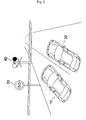
traffic facilities according to the present invention; FIG. 2 is an
explanatory view showing the operation of the automatic guide
apparatus for traffic facilities according to the present invention;
where the traffic facilities are a motor vehicle; FIG. 3 is an
explanatory view showing the operation of the automatic guide
apparatus for traffic facilities according to the present invention;
where the traffic facilities are a railroad vehicle; FIG. 4 is an
explanatory view showing the operation of the automatic guide
apparatus for traffic facilities according to the present invention;
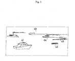
where the traffic facilities are an airplane; FIG. 5 is an explanatory
view showing the operation of the automatic guide apparatus for
traffic facilities according to the present invention; where the traffic
facilities are a ship; FIG. 6 is a structural view of a plane
development processing apparatus to be mounted on the automatic
guide apparatus for traffic facilities according to the present
invention; FIG. 7 is a view, in a system in which a perspective image
obtained by a video camera is subjected to plane development and
converted into a plane image from which a perspective sense is
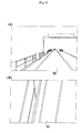
eliminated, showing a variable to be used; FIG. 8 (A) is a perspective
image obtained by an input device, and (B) is a development view
converted by a plane image conversion device; FIG. 10 is an
explanatory view showing a space physical amount to be measured by
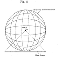
an image content measuring device; FIG. 11 is an explanatory view
showing the concept in which a 360-degree whole periphery image is
subjected to plane development and converted into a plane image;
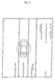
FIG. 12 is an example of a plane image converted from the 360-degree
whole periphery image; FIG. 13 is an explanatory view showing an
installation example of a traffic information detecting device in the
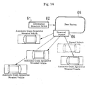
road; FIG. 14 is an explanatory view showing a transmission example
from a traffic information detecting device to an automatic guide
apparatus for traffic facilities; FIG. 15 is an example of an output
screen to be displayed as a computer graphic image where a vehicle
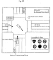
travel on the road; FIG. 16 is an example of an output image to be
displayed as a graphic image, where the vehicle moves into a
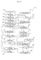
crossing; FIG. 17 is a structural view of a position relation
recognition device mounted on the automatic guide apparatus for
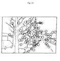
traffic facilities according to the present invention; FIG. 18 is a view
showing an example of an object portion and part thereof to be
selected as a clue point in the position relation recognition device
shown in FIG. 17; and FIG. 19 is a conceptual view showing a
superposed state of a field of view in a plurality of cameras mounted
on a vehicle.
BEST MODE FOR CARRYING OUT THE INVENTION
The preferred embodiments of the automatic guide apparatus
for traffic facilities according to the present invention will be
described in detail hereinafter with reference to the drawings.
The automatic guide apparatus for traffic facilities 1 according
to the present invention comprises, as shown in FIG. 1, an input
device 2, a database 3, a comparison device 4, a recognition device 5,
an output device 6, a judgment device 7, a storage device 8, and a
data updating device 9.
The input device 2 is a device for, when the traffic facilities are
operated, obtaining the circumstances around the traffic facilities as
an image, a voice or the like. For example, an image and a voice are
obtained by a video camera and a microphone, respectively.
In the database 3 are stored in advance, in case of a motor
vehicle, a road mark, a road sign, a traffic guide plate or the like, and
image data, voice data or the like related to a motor vehicle. In case
of a train, a crossing surface, a crossing signal, a moving obstacle, a
platform or the like, and image data, voice data or the like related to
a train are stored. In case of an airplane, an airport shape, a runaway
of an airport, an induction path, a structure such as a control tower, a
moving obstacle such as a motor vehicle, and image data, voice data
or the like related to an airplane or the like are stored. In case of a
ship, a harbors shape, a quay of harbors, a wharf, and a fairway mark,
and image data, voice data or the like related to a ship or the like are
stored.
The comparison device 4 compares image data, voice data or
the like obtained by the input device 2 with image data, voice data or
the like stored in the database 3.
The recognition device 5 recognizes and specifies, on the basis
of the results obtained by comparing the image data, the voice data or
the like, contents of the data.
The output device 6 is a device for informing an operator or the
like of the results recognized and specified by the recognition device
5 in a letter or a character, an image, a voice or the like.
The storage device 8 is a device for allowing, where the image
data, voice data or the like corresponding to the objects obtained by
the input device 2 are not present within the database, the image
data, voice data or the like corresponding to the new objects
correspond to a position on a map to newly store them in the
database 3.
The data updating device 9 is a device for updating, where
even if the object is present on a fixed position on the map, image
data, voice data or the like corresponding to the object are different
from the image data, voice data or the like stored in the database 3,
them to new image data, voice data or the like to store them in the
database 3.
The judgment device 7 is a device for carrying out, on the basis
of the matter recognized or specified by the recognition device 5,
some judgment, wherein the output device 6 informs an operator or
the like of a direction based on the judged results in a letter or
character, an image, a voice or the like.
Further, the judgment device 7 sometimes directs the output
device 6 of a fixed action on the basis of judged results to
automatically actuate a brake device such as a brake, and a handling
device such as a handle.
In the following, a specific description will be made of an
example, where the traffic facilities are a motor vehicle, in which the
automatic guide apparatus 1 for traffic facilities automatically
recognizes the circumstances of the own vehicle to inform a driver or
an occupant of the circumstances in a letter or character, an image, a
voice or the like, to guide the road, and to direct adequate action at
the time of travel on the road.
[Embodiment 1]
As shown in FIG. 2, a road mark 12 whose regulation speed is
50 km is obtained as image data by the input device 2, first, the
image data is compared with the image data stored in the database 3
by the comparison device 4, and it is recognized and specified as road
mark data whose regulation speed is 50 km by the recognition device
5.
Then, the fact that the regulation speed is 50 km is informed,
on the basis of the recognized results to a driver or an occupant in a
letter or character, an image, a voice or the like by the output device
6.
As described above, according to the automatic guide
apparatus for traffic facilities 1, also where a driver or an occupant
overlooks the road mark 12, it is possible to know positively that in
the road being currently traveled, the regulation speed is 50 km to
enable preventing a violation of the traffic regulations caused by the
over-speed and also to enable preventing an occurrence of a rear-end
collision or the like.
[Embodiment 2]
As shown in FIG. 2, where the other vehicle 13 is obtained as
image data on the right side of the own vehicle 11 by the input device
2, the image data is compared with image data stored within the
database by the comparison device 4, and the other vehicle 13 is
recognized as a passing vehicle by the recognition device 5.
Then, the judgment device 7 carries out judgment that the
other vehicle 13 does not accelerate during passing, and the output
device 6 informs a driver or an occupant of a direction that not to
accelerate in a letter or character, an image, a voice or the like.
As described above, according to the automatic guide
apparatus for traffic facilities 1, also where a driver or an occupant
does not become aware of the fact that the other vehicle 13 is present
on the right side of the own vehicle 11, the driver or occupant is able
to know positively that the other vehicle 13 is passing, and it is
possible to prevent an occurrence of trouble such as collision with
great presence of mind by the direction so as not to accelerate.
[Embodiment 3]
As shown in FIG. 2, where a red lamp present ahead is turned
on and off by the input device 2, and a crossing signal 14 at which an
alarm is ringing is obtained as image data, voice data or the like,
first, they are compared with the image data, voice data or the like
stored in the database 3, and the fact that the red lamp of the
crossing signal 14 ahead is turned on and off and the alarm is ringing
is recognized by the recognition device 5.
Then, the judgment device 7 carries out judgment that should
be stopped on the basis of the recognized results, and directs the
output device 6 to actuate the brake in consideration of the fact that
moving into the crossing is dangerous and prohibited by the law also.
Thereby, the output device 6 causes the brake to actuate, and
therefore, the motor vehicle automatically stops at a safety position
before the crossing.
As described above, according to the automatic guide
apparatus for traffic facilities 1, also where a driver or an occupant
does not become aware of the fact that the red lamp of the crossing
signal 14 is turned on and out and the alarm is ringing ahead, and
where even if he becomes aware, he did not take adequate action, the
apparatus is able to positively inform that moving into the crossing is
dangerous because the red lamp of the crossing signal 14 is turned on
and out and the alarm is ringing, to direct and execute the adequate
action of automatically stopping, thus enabling prevention of an
occurrence of accidence or the like doing serious damage.
Next, where the traffic facilities are a train, a specific
description will be made of an example wherein the automatic guide
apparatus for traffic facilities 1 automatically recognizes the
circumstances of the own vehicle, informs a driver or an occupant of
the circumstances in a letter or character, an image, a voice or the
like to guide a line or to direct adequate action when traveling on the
line.
[Embodiment 4]
As shown in FIG. 3, where a platform 21 is obtained as image
data ahead of the own vehicle by the input device 2, first, it is
compared with the image data stored in the database 3 by the
comparison device 4, and the fact that a stop station is near is
recognized by the recognition device 5.
Then, the judgment device 7 carries out, on the basis of the
recognized results, judgment that since a stop station is near,
deceleration is made, and the output device 6 informs a driver or an
occupant of a direction of making deceleration by an image, a voice or
the like.
As described above, according to the automatic guide
apparatus for traffic facilities, also where a driver or an occupant
does not become aware of the fact that the platform 24 is present
ahead of the own vehicle, it is possible to positively know that a stop
station is near, and it is possible to prevent the vehicle from passing
the stop station due to an error by the direction of making
deceleration.
[Embodiment 5]
As shown in FIG. 3, where a crossing surface 22, a crossing
signal 23 and a moving obstacle 24 such as a motor vehicle are
obtained as image data or voice data ahead of the own vehicle by the
input device 2, first, they are compared with the image data or the
voice data stored in the database 3, and that fact that a red lamp of a
crossing signal 23 ahead is turned on and out, and an alarm is
ringing, and the fact that a moving obstacle 24 such as a motor
vehicle is present at the crossing surface 22 are recognized by the
recognition device 5.
Then, the judgment device 7 carries out, on the basis of the
recognized results, judgment that the vehicle has to be stopped
urgently, and directs the output device 6 of immediately actuating a
brake in consideration of the fact that moving into the crossing
surface 22 is dangerous. Thereby, since the output device 6
immediately actuates a brake, the own vehicle automatically stops
urgently at a safety position before the crossing surface 22.
As described above, according to the automatic guide
apparatus for traffic facilities 1, also where a driver or an occupant
does not aware of the fact that the red lamp of the crossing signal 23
is turned on and out, and the alarm is ringing, and the fact that the
moving obstacle 24 such as a motor vehicle is present on the crossing
surface 22, and further, where even if he becomes aware of it,
adequate action has not been taken, the apparatus is able to
positively inform that the red lamp of the crossing signal 23 is turned
on and out and the alarm is ringing, and moving into the crossing
surface 22 is dangerous, and direct adequate action of automatically
rapidly stopping the vehicle, thus enabling preventing an occurrence
of a crossing accident or the like doing great damage.
Next, a description will be made specifically of an example
wherein where the traffic facilities are an airplane, the automatic
guide apparatus for traffic facilities 1 automatically recognizes the
circumstances of the own vehicle, informs an operator or an occupant
of the circumstances in a letter or character, an image, a voice or the
like, guides the navigating route or the interior of an airport, and
directs adequate action when navigating the route and traveling the
interior of the air port.
[Embodiment 6]
As shown in FIG. 4, where moving obstacles such as the other
body 32, a motor vehicle 32 or the like are obtained as image data or
voice data ahead of the own body 31 by the input device 2, first, they
are compared with the image data or the voice data stored within the
database 3 by the comparison device 4, and the fact that the moving
obstacles such as the other body 32, the motor vehicle 32 or the like
are present ahead is recognized by the recognition device 5.
Then, the judgment device 7 carries out, on the basis of the
recognized results, judgment that the vehicle has to be stopped
urgently, and directs the output device 6 so as to immediately actuate
a brake in consideration of the fact that moving ahead is dangerous.
Thereby, since the output device 6 causes the brake to be immediately
actuated, the own body 31 automatically stops urgently at a safety
position before the moving obstacle.
As described above, according to the automatic guide
apparatus for traffic facilities 1, also where an operator or an
occupant does not become aware of the fact that the moving obstacles
such as the other body 32, the motor vehicle 33 or the like are present
ahead of the own body 31, and further, where even if becoming aware,
adequate action has not been taken, the apparatus is able to
positively inform that the moving obstacle is present ahead and
moving ahead is dangerous, to direct and execute adequate action of
automatically stopping urgently, thus enabling preventing an
occurrence of accident of an airplane or the like doing great damage.
Next, a description will be made specifically of an example
wherein where the traffic facilities are a ship, the automatic guide
apparatus for traffic facilities 1 automatically recognizes the
circumstances of the own ship, informs an operator or an occupant of
the circumstances in a letter or character, an image, a voice or the
like, guides the navigating route or the interior of a harbor, and
directs adequate action when navigating the route and navigating
the interior of the harbors.
[Embodiment 7]
As shown in FIG. 5, where when a ship 41 navigates in order to
reach the shore within the harbors 45, a waterway, a wharf 43, and a
quay 44 are obtained as image data, first, they are compared with the
image data or the voice data stored within the database 3 by the
comparison device 4, and the waterway, the wharf 43, and the quay
44 are recognized by the recognition device 5.
Then, the judgment device 7 judges, on the basis of the
recognized results, the navigating route from a position reaching the
shore of the quay 44 and the current position of the ship 41, and the
relative laws and ordinances such as the harbors law, the maritime
traffic safety law or the like, and the output device 6 informs an
operator or an occupant of a direction about the navigating route in a
letter or character, an image, a voice or the like.
As described above, according to the automatic guide
apparatus for traffic facilities 1, also where an operator or an
occupant is unfamiliar with the shape of the harbors 45, the
navigating route to the position reaching the ashore of the quay 44
can be known easily, thus enabling smoothly reaching the ashore to
the quay 44, and enabling relieving confusion of the ship within the
harbors 45.
[Embodiment 8]
As shown in FIG. 5, where the other ship 42, a wharf 43, a
quay 44, a shoal or the like are obtained as image data and voice data
ahead of the own ship 41 by the input device 2, first, they are
compared with the image data or the voice data stored within the
database 3 by the comparison device 4, and the fact that the other
ship 42, the wharf 43, and the quay 44, shoal or the like are present
is recognized by the recognition device 5.
Then, the judgment device 7 judges, on the basis of the
recognized results, urgent stop or change in route has to be made,
and directs the output device 6 so as to immediately take action of
urgently stopping or changing the route for the ship 41 in
consideration of a danger of being navigated as it is. With this, since
the output device 6 causes the ship 41 to be stopped urgently or to
change the route, the ship 41 is automatically stopped at a safety
position or moves to a safety position.
As described above, according to the automatic guide
apparatus for traffic facilities 1, also where an operator or an
occupant does not become aware of the fact that the other ship 42, the
wharf 43, and the quay 44, shoal or the like are present ahead, and
where even if becoming aware of it, adequate action has not been
taken, the apparatus is able to positively inform that the other ship
42, the wharf 43, and the quay 44, shoal or the like are present, and
navigation as it is dangerous, to direct and execute adequate action
of automatically stopping urgently and changing the route, enabling
preventing an occurrence of accident of a ship or the like doing great
damage.
Alternatively, in the automatic guide apparatus for traffic
facilities 1, any one or a plurality of devices out of the input device 2,
the database 3, the comparison device 4, the recognition device 5, the
output device 6, the judgment device 7, the storage device 8 and the
data updating device 9 which constitute the apparatus 1 may
connected to the other devices constituting the automatic guide
apparatus for traffic facilities 1 through communication lines.
According to the structure as described above, it becomes
possible to remote-control the traffic facilities in a central control
center.
As described above, according to the automatic guide
apparatus for traffic facilities, an enormous quantity of image data,
voice data or the like can be processed at high speeds, and it is
possible to automatically recognize the circumstances around the
traffic facilities which momentarily change and to automatically
guide the operating route.
Further, in the automatic guide apparatus for traffic facilities
1 according to the present invention, there can be added a plane
development processing device 51.
The plane development processing device 51 is a device in
which a perspective image obtained by the input device 2 about the
circumferences around the operating traffic facilities is subjected to
plane development thereby to be converted into a plane image from
which perspective sense is eliminated, on the basis of which
measuring process for a distance, an area or the like is executed, and
comprises, as shown in FIG. 6, a plane image conversion device 52, a
plane image recognition device 53, a plane image coupling device 54,
and an image content measuring device 55.
When the traffic facilities are operated, the circumstances
around the traffic facilities are obtained as a perspective image by
the input device 2.
The plane image conversion device 5 is a device for subjecting
the obtained perspective image to plane development to be thereby
converted into a plane image.
The perspective image obtained by a video camera as the input
device 2 is subjected to plane development by the following Equations
(1) and (2) using variables shown in FIG. 7, for example.
y = v · 21/2 · h · cos (π / 4 - ) · cos (β - )/(f · sinβ)
x = u · h · cos (β - ) / (f · sinβ)
Wherein is an angle formed between an optical axis of a
camera and a plane of the road surface or the like; f is a focal distance
of the camera; h is a height of the camera; β is an angle formed
between a line segment for joining a point in a distance from a
portion directly below the camera to h+y with the camera, and a
plane of the road surface or the like; v is a coordinate in a
longitudinal direction from an original point on the projection
surface of the camera; u is a coordinate in a lateral direction from an
original point on the projection surface of the camera; y is a
longitudinal coordinate whose original point is a point moved by h
from a portion directly below the camera in the plane such as the
road surface; and x is a lateral coordinate in the plane such as the
road surface.
The plane image recognition device 53 is a device for
recognizing and specifying, on the basis of the results obtained by
comparing the converted plane image data with the image data stored
in the database 3, the content of the data.
The plane image coupling device 54 is a device for suitably
coupling the converted plane image data to produce plane image data
of a large screen.
The image convent measuring device 55 is a device for
measuring various space physical amounts in connection with objects
recognized and specified by the plane image recognition device 53.
The space physical amounts include a position, a distance, an area, a
height, a depth, a volume, a speed, an acceleration or the like.
Next, a specific description will be made of an example
wherein where the traffic facilities are a vehicle traveling on the road
such as a motor vehicle, a fixed space physical amount is measured
and processed by the plane development processing device 51.
[Embodiment 9]
As shown in FIG. 8 (A), where a traveling lane 56 extending
ahead of the own vehicle is obtained as perspective image data by the
input device 2, first, the data is converted into plane image data as
viewed from the vertical top with a perspective sense eliminated, as
shown in FIG. 8 (B), by the plane image conversion device 52. Here,
the contents of the converted plane image data are recognized and
specified by the plane image recognition device 53, to recognize and
specify the fact that the traveling lane 56 is present within the plane
image.
Then, various space physical amounts of a lane width, a
parallelism of a lane or the like are measured, in connection with the
traveling lane 56 as an object, as shown in FIG. 8 (B), by the image
content measuring device 55. Further, if perspective image data is
obtained at real time by the input device 2, a moving distance per
time is measured to thereby enable measuring an advancing speed of
the own vehicle.
Next, a specific description will be made of an example
wherein where the traffic facilities are a vehicle traveling on the
track such as a train, a fixed space physical amount is measured and
processed by the plane development processing device 51.
[Embodiment 10]
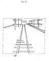
Where a track 57 extending ahead of the own vehicle is
obtained as perspective image data by the input device 2, as shown in
FIG. 9 (A), first, the data is converted into plane image data as
viewed from the vertical top with a perspective sense eliminated, as
shown in FIG. 9 (B), by the plane image conversion device 52. Here,
the contents of the converted plane image data are recognized and
specified by the plane image recognition device 53, to recognize and
specify the fact that the track 57 is present within the plane image.
Then, various space physical amounts of a rail width, a rail
parallelism or the like are measured, in connection with the track 57
as an object, as shown in FIG. 10, by the image content measuring
device 55. Further, if perspective image data is obtained at real time
by the input device 2, a moving distance per time is measured to
thereby enable measuring an advancing speed of the own vehicle.
As described above, according to the plane development
processing device 51, which is annexed to the automatic guide
apparatus for traffic facilities 1, various space physical amounts in
connection with the circumstances around the traffic facilities can be
obtained when operating the traffic facilities.
Further, it is also possible to issue more adequate notice and
direction on the basis of the obtained space physical amounts in the
automatic guide apparatus for traffic facilities 1.
The plane development processing device 51 may have not only
a function of converting a perspective image into a plane image, but
also a function of converting a 360-degree whole peripheral image
(spherical image) into a plane image.
The 360-degree whole peripheral image is an image which
grasps the whole periphery of the operating traffic facilities, that is,
all directions including before and behind, left and right, and top and
bottom, which image can be obtained by methods, for example, 1 ○
images photographed by many cameras are synthesized, 2 ○ a curved
mirror is installed on the front surface of a camera, and an image
projected on the curved surface is photographed, 3 ○ a single camera
is rotated, and images photographed at respective positions are
synthesized, and 4 ○ a fish-eye lens is mounted on the camera, and an
image photographed in a wide range is processed.
If the 360-degree whole peripheral image is regarded as an
image attached onto an imaginary spherical surface, as shown in FIG.
11, the converted plane image can be grasped as an image projected
on the plane as viewed from a desired visual point.
Where the circumstances around a motor vehicle traveling on
the road surface are obtained as the 360-degree whole peripheral
image by the methods as described above, an example is shown in FIG.
12, in which the image is converted into a plane image with the top of
a motor vehicle as a visual point.
While in the foregoing, a description has been made of
examples in which the traffic facilities are a vehicle traveling on the
road surface such as a motor vehicle, and a vehicle traveling on the
track such as a train, it is noted that the same is also applied to an
airplane, a ship or the like.
Further, alternatively, a traffic information detection device
61 is separately installed on the operating route of the traffic
facilities so that image data, measured data or the like obtained by
the traffic information detection device 61 may be transmitted to the
automatic guide apparatus for traffic facilities 1.
The traffic information detection device 61 comprises, in the
automatic guide apparatus for traffic facilities 1, the input device 2,
the database 3, the comparison device 4, the recognition device 5, the
storage device 8, the data updating device 9, the plane development
processing device 51, and a graphical device 62.
The graphical device 62 is a device for forming computer
graphic (CC) on the basis of image data and measured data obtained
from the input device 2.
Next, a specific description will be made of an example
wherein where the traffic facilities are a motor vehicle, image data,
measured data or the like obtained by the traffic information
detection device 61 installed on the operating route are transmitted
to the automatic guide apparatus for traffic facilities 1.
[Embodiment 11]
In case of a motor vehicle, the traffic information detection
device 61 is installed on a gate 63, an illumination lamp 64 or the like
provided on the road as shown in FIG. 13, for example. And, as shown
in FIG. 14, image data, measured data or the like obtained by the
traffic information detection device 61 are, first, transmitted to a
base station 65 installed for the purpose of concentrating and
controlling data, then delivered to a plurality of terminal stations 66
installed on suitable locations, and transmitted from the terminal
stations 66 to the respective vehicles on which the automatic guide
apparatus for traffic facilities 1 is mounted.
The image data, measured data or the like to be delivered from
the traffic information detection device 61 to the respective vehicles
on which the automatic guide apparatus for traffic facilities 1 is
mounted through the base station 65 and the terminal stations 66 are
formed into computer graphic images (CG), which are transmitted
together with figures, numerical values or the like. Therefore, in the
automatic guide apparatuses for traffic facilities 1 of the respective
vehicles, they are displayed in figure, numerical value, letter or the
like, as shown in FIG. 15, which is very convenient.
In an output screen formed into computer graphic, the
coordinate of the own vehicle is fixed to a suitable position, and the
circumferences around the traveling own vehicle, that is, positions or
displays of the road mark, rod sign, traffic guide plate, other vehicles
or the like are to be changed momentarily when passing through the
traffic information detection device 61.
It is noted that images displayed on the output screens may be,
not limiting to the plane computer graphic image, a
three-dimensional computer graphic image (3DCG) or may be an
image synthesized with an actual image subjected to plane
development.
An output screen shown in FIG. 15 shows a case where other
vehicles which infringe or possibly infringe a preset safety zone of the
own vehicle are present, and this informs a driver or an occupant in a
letter or character, a voice or the like such as "Passing vehicle is
present Speed per hour: 140 km".
[Embodiment 12]
The recognition of traffic information by transmission from the
traffic information detection device 61 to the automatic guide
apparatus for traffic facilities 1 makes it possible to easily grasp,
particularly where in a crossing or the like, left and right roads are
the dead point from the own vehicle, as shown in FIG. 16, the traffic
circumstances of the left and right roads, which is very useful in
terms of the traffic safety measures.
An output screen shown in FIG. 16 shows a case where other
vehicles are present at a position at which the left and right roads
are the dead angle from the own vehicle, and this informs a driver or
an occupant in a letter or character, a voice or the like such as
"Right-turn vehicle is present ahead".
While in the foregoing, a description has been made taking an
example in which the traffic facilities are a motor vehicle traveling
on the road surface, it is to be noted that this can be likewise applied
also to a vehicle traveling on the track such as a train, an airplane, a
ship or the like.
Further, if in the automatic guide apparatus for traffic
facilities 1, a device capable of accurately recognizing a positional
relation between the operating traffic facilities and the
circumference is added, it is possible automatically guide the traffic
facilities more effectively.
In the following, a description will be made of a positional
relation recognition device 101 capable of accurately recognizing a
positional relation between the operating traffic facilities and the
circumference, where traffic facilities are a vehicle traveling on the
road surface such as a motor vehicle.
As the apparatus for recognizing a positional relation of an
operating vehicle to guide the vehicle, there has been already
developed an apparatus for detecting a while line attached to the
road from a picture obtained by a camera mounted, and guide the
vehicle so as not to protrude from the while line.
In the above apparatus, the own vehicle is positioned only in
the relation with the white line, limiting to a special object called a
white line. Therefore, in the road having a white line not attached, a
position recognition function and an automatic guiding function stop,
and if a white line is formed to be curved, an erroneous operation
possibly occurs. Further, where advancing along the white line like a
crossing is not always in line with the purpose, a position recognition
function and an automatic guiding function have no meaning at all.
Further, there is a fear that those other than a white line are
erroneously recognized as a white line, and even if traveling along
the white line, where an obstacle is present, it is not possible to avoid
it.
The positional relation recognition apparatus 101 according to
the present invention is an apparatus which recognizes, making use
of not only the white line attached to the road but also all objects in
the picture obtained by a camera, a three dimensional position of the
own vehicle, and which is able to three-dimensionally position the
own vehicle in the peripheral circumstances.
That is, in the positional relation recognition apparatus 101,
not only the white line attached to the road but also all objects
present in the picture serve as a clue for three dimensional
measurement. Further, not the objects themselves, but a part that is
easily extracted by the image process in the objects serves as a clue.
Further, a plurality of those which tend to be clue for the three
dimensional measurement in the objects are extracted. Furthermore,
the objects are not extracted at the outset, but there is characterized
in that objects that could be extracted serve as a clue.
In the respective images of a continuous image in which the
clue portions in the picture are produced by the advancement of the
vehicle, an image processing technique such as a matching method is
applied for automatic tracking. The tracking is sometimes succeeded,
or the tracing is sometimes failed. However, only the clue portion
that succeeded the tracking may be employed as an object of three
dimensional measurement.
On the basis of a plurality of clue portions that succeeded the
tracking during the vehicle is moving for suitable distance, a fixed
calculation is carried out to thereby detect and recognize the three
dimensional position and direction of the own vehicle.
Further, a plurality of cameras are mounted so that fields of
view are not superposed, a corresponding point is detected among the
superposed fields of view and three dimensional measurement is
carried out. And, a three dimensional position and a direction of the
own vehicle are positioned in the three dimensional coordinate
constituted by portions to be peripheral clues, or in the peripheral
three dimensional image obtained by other methods.
According to the positional
relation recognition apparatus 101
in the present invention,
As described above, according to the positional relation
recognition apparatus 101, various functions that never be done by
the position detection of the own vehicle merely by the white line can
be displayed.
And, the peripheral traffic circumstances are judged, which is
transmitted to the operator, or the vehicle is controlled directly on
the basis thereof, and the higher-level traffic guidance can be
realized, thus enabling contributing to the traffic safety effectively.
The positional relation recognition apparatus 101 according to
the present invention is an apparatus which detects, on the basis of
picture information of the road surface, the peripheral body or the
like photographed by an output device such as a video camera
mounted on the vehicle, a three dimensional position of the road
surface, the peripheral body or the like and the own vehicle so as to
be able to recognize a positional relation with the road surface. The
apparatus is characterized in comprising: an image obtaining portion
102 for obtaining an image by an input device mounted on the
vehicle; an image temporarily recording portion 103 for recording the
obtained image for a certain period; a clue point automatic extrusion
portion 104 for automatically extracting a clue point for taking a
corresponding point within the image; a corresponding point
detection portion 105 for defecting a corresponding point of a
plurality of clue points in the respective images; an input device
position and direction measuring portion 106 for calculating a
position and direction of the input device; and an actually measured
scale conversion portion 107 for converting a relative distance in a
three dimensional coordinate at a position of the calculated input
device into an absolute distance using the actually measured value.
According to the mage obtaining portion 102 and the image
temporarily recording portion 103, a picture from the input device
such as a video camera mounted on the own vehicle, and by arranging
them on the time axis, an image which changes in time as the vehicle
advances is obtained. That is, in connection with a static object, there
is obtained a result similar to that photographed by arranging a
plurality of cameras on the road on which the vehicle advances. By
doing so, even a single camera is used, a plurality of parallaxes can
be obtained by moving the cameras.
Next, by the clue point automatic extracting portion 104, a
contour of an image is extracted in order to make a feature point in
an image a clue point, or divided into color areas to automatically
extract the feature portion in the image.
The clue point termed herein means, in order to obtain a
corresponding point between images photographed at points different
n position, a feature point within the image to be the corresponding
point. The clue point is sometimes an object itself, but is often a
portion of the object. Further, since the feature point is not a feature
point for a human being but may be a feature point for a computer
which processes an image, the image processing is extremely
advantageous.
It is not necessary to specify a clue point to be detected at the
outset, but an object that could be detected easily in the actual site at
that time or a portion thereof can be employed as a clue point.
Further, with respect to a plurality of clue points detected, it is not
necessary to specify a clue point to be tracked at the outset, but only
the clue point that could be tracked can be employed as a clue point
for a calculation object for a three dimensional measurement. By
these features, the recognition by the positional relation recognition
apparatus 101 can be realized.
Next, by the corresponding point detection portion 105 and the
input device position and direction measuring portion 106, a
plurality of corresponding points are detected by an image matching
method or the like, and an input device position and direction of a
camera or the like is obtained by calculation on the basis of
coordinates of the respective corresponding points.
Here, the position and direction of the input device are
continuously obtained, whereby the speed of the input device, that is,
the vehicle speed, the vehicle acceleration, and the vehicle advancing
direction can be obtained.
Some corresponding points are hidden as a vehicle moves, but
if many clue points are sufficiently selected, and several clue points
are remained finally, this will suffice to enable calculation
satisfactorily.
Further, an object secured to a static coordinate system has to
be selected to a clue point, but sufficiently many clue points are
selected, and statistics processing is applied thereto to delete those
indicative of abnormal values and leave only effective clue points,
whereby the three dimensional measurement becomes enabled.
The data of a camera position obtained by calculation is a
relative distance, and for converting it to an absolute distance, one or
more known distances are necessary in connection with the
corresponding point coordinate or the vehicle position coordinate
which is an object to be measured. However, as the value which is not
changed in distance as the vehicle travels, for example, a height
where a cameral is installed or a distance known at the outset within
the image may be used and calibrated. Further, where a plurality of
cameras are installed, the distance between the cameras can be
employed as a known distance. Furthermore, if the known actually
measured value is present in the object within the image, it can be
converted to an absolute distance by the actually measured scale
conversion portion 107.
In the way as described above, the camera position and
direction can be measured in a three-dimensional manner.
To the above-described positional relation recognition device
101 may be added a corresponding point three dimensional
measuring portion 108 for three dimensional measuring a plurality of
clue points from corresponding points within the respective images of
a plurality of clue points to obtain a relation between them and a
camera position as a three dimensional coordinate.
According to the corresponding point three dimensional
measuring portion 108, three dimensional data of a clue point is also
obtained simultaneously during the calculation for obtaining the
three dimensional data of the position and direction of a camera.
Thereby, it is possible to arrange a camera position in a three
dimensional position of a plurality of clue points, a three dimensional
disposition, and a two dimensional distribution. That is, the position
and direction of a vehicle can be arranged in a three dimensional
manner in the same three dimensional coordinate system as the three
dimensional distribution of a plurality of clue points in the periphery.
Whereby, a position of the own vehicle, correctly, a camera
mounted on the own vehicle can be positioned in a three dimensional
manner in a static object in a static coordinate system in the
periphery, in other words, in a three dimensional coordinate
including peripheral buildings, poles, roads or the like.
Further, there can be added a three dimensional data
recording portion 109 for recording a three dimensional coordinate of
a corresponding point obtained by the corresponding point three
dimensional measuring portion 108.
The three dimensional data of the clue point obtained by the
calculation is recorded and left, whereby when traveling around later,
the clue point having obtained three dimensional coordinate already
may be referred to as an index of the calculation of the position and
direction of the vehicle.
Actually, a vehicle having an exclusive-use device mounted in
advance is traveled, and three dimensional data of more accurate
clue points are collected, whereby many vehicles may use them later.
Further, there can be added a three dimensional data read-out
portion 110 for reading out three dimensional data of clue points
accumulated in the three dimensional data recording portion 109
from the three dimensional data recording portion 109 when
traveling in the periphery thereafter; and a corresponding point
comparison portion 111 for comparing those data with the three
dimensional data obtained when traveling thereafter to obtain a
coincided point, thus enhancing calculation accuracy of a vehicle
position.
The three dimensional data are read out by the three
dimensional data read-out portion 110 from the three dimensional
data recording portion 109, and if there is a change in a coordinate of
a previous clue point every time of later travel, its coordinate may be
updated and recorded again as new data.
As the travel near the same place is repeated, the data of the
three dimensional data recording portion 109 are updated and added
newly, whereby the clue points are increased, or the position accuracy
is enhanced, and the calculation accuracy of the position and
direction of the vehicle is also enhanced.
The three dimensional data of high accuracy are produced by
the exclusive-use device in advance, which are used later by other
vehicles, whereby the position accuracy of the clue point is enhanced
extremely. Further, if three dimensional map data having a clue point
expanded to a pixel unit are produced in advance by the exclusive-use
device, a three dimensional space around the travel path is
constituted, within which position and direction of a vehicle can be
arranged.
Further, there can be added an absolute coordinate conversion
portion 112 for selecting an object whose absolute coordinate is
known at a corresponding point, and imparting an absolute
coordinate to three dimensional data obtained by the input device
direction measuring portion 106 and the corresponding point
measuring portion 108; and a coordinate unifying portion 113 for
unifying a three dimensional coordinate of a clue point present in an
area relative to an absolute coordinate system.
Acceding to the absolute coordinate conversion portion 112, for
example, an absolute coordinate of a camera position is obtained by
GPS, or three dimensional data obtained as a relative distance can be
converted to an absolute coordinate with an object whose latitude and
longitude are known as a clue.
Further, according to the coordinate unifying portion 113,
coordinates of some clue points can be unified in a common absolute
coordinate system and displayed, and the three dimensional data is
to obtain the absolute coordinate immediately.
If the clue point obtains the absolute coordinate, thereafter
also, or even other vehicles can use it as three dimensional data
whose clue point is common.
Site data coincided with three dimensional data having clue
points collected is to have obtained an absolute coordinate because of
being coincided with a position, disposition and distribution of clue
points. Then, a camera position, that is, an absolute coordinate of a
vehicle can be obtained immediately.
Further, a three dimensional coordinate by way of a clue point
is dropped into a map of the whole area whereby a map and a clue
point are connected to create new data, and many vehicles may obtain
a map for recording data of position and direction of the own vehicle
as common data.
Further, there can be added a name attribute adding portion
114 for corresponding a name and attribute of a clue point to position
data of a clue point to record and store them, and adding a name and
attribute of an object to which a clue point belongs to coordinate data
of the clue point; and a database 115 for relating a coordinate, name
and attribute of the added clue point into a map to write, record and
store them.
If the name and attribute of the object to which a clue point
belongs are known in advance, or if a name is known by the image
recognition, the name of the object, its general properties, or
properties peculiar to the object can be also obtained as attribute
data.
That is, if the clue point at the time of measurement is
corresponded to the clue point in the database, the name and
properties of the object at the clue point can be read.
Further, there can be also added a display portion 116 for
suitably displaying and informing a driver or the like of various
calculation results as described above.
If the obtained data, position and direction of the vehicle, the
name and attribute of the object to which clue point belongs or the
like are displayed by the display portion 116, the driver or a manager
observes them to enable judging the circumstances.
There can be added a circumstance judgment portion 117 for
automatically judging the circumstances of a vehicle from a
positional relation between the periphery and the own vehicle and a
positional relation between the road and the own vehicle by the
calculation results; and an automatic vehicle control portion 118 for
automatically carrying out operations (such as brake operation,
speed control operation, handle operation, alarm operation or the
like) suited to an object of a vehicle automatically, using the results
obtained by judging the circumstances.
According to the circumstance judgment portion 117, the
position and direction of the own vehicle, the name and attribute of
the object to which clue point belongs, name and attribute of the clue
point, positional relation between the road surface and the vehicle,
mark, road sign or the like are synthetically judged to enable judging
the circumstances of the vehicle.
Whereby, the vehicle can be operated automatically or
semi-automatically through the automatic vehicle control portion 118.
Further, the positional relation between the circumstances of the
periphery and the vehicle is judged to enable transmitting position
information of the vehicle to a driver or the like.
Further, there can be added a plural camera image obtaining
portion 119 for installing a plurality of cameras to take in images,
and superposing part or the whole field of view of the respective
cameras; and a calibration portion 120 for jointly using both three
dimensional distance measurement calculated from the parallax
caused by a moving distance of a single camera and three
dimensional distance measurement calculated from the parallax
between cameras by a plurality of cameras, calibrating the three
dimensional distance data obtained by the moving distance parallax
system by movement of a single camera, with three dimensional
distance data of clue points obtained by the field of view superposing
system of a plurality of cameras as a reference length, to thereby
convert the former to an absolute distance.
If a plurality of cameras are installed on the vehicle so as to
surround the vehicle so that the circumference of the vehicle may be
observed, the field of view of each camera is partly superposed to that
of other cameras, it is possible to generate the parallax between
cameras in the superposed portion.
The greatest characteristics of the three dimensional distance
measurement by the plural camera field of view superposing system
is that even the moving body can be measured. Further, according to
the plural camera field of view superposing system, high accuracy is
created in the measurement of a short distance.
On the other hand, according to the single camera moving
distance system, since the distance between cameras in the plural
camera system can be made long distance substantially, it is
advantageous when a three dimensional distance of long distance is
measured. For example, a distance between cameras in the camera
mounted on the vehicle is about 1 m at most, but a distance between
cameras in the camera moving distance system can be made not only
1 m, 10 m, 100 m but also 1 km, 10 km.
So, the short distance is subjected to three dimensional
measurement by the field of view superposing system, and the long
distance is subjected to three dimensional measurement by the
camera moving distance system by which the parallax is taken
greatly.
Fundamentally, the principle of measurement is the same in
case of single and in case of plural. However, as the characteristics of
the plural camera system in which fields of view are superposed, the
distance between cameras can be taken as a reference length in the
measurement by the parallax, because of which absolute distance
measurement can be done; moreover, since the measured distance by
the single camera moving system can be calibrated by distance data
of intermediate distance measurement obtained from the distance
measurement by the parallax, accurate measurement from short
distance to long distance becomes enabled. That is, a position, speed,
acceleration, and advancing direction of a vehicle traveling ahead
can be measured.
Further, there can be added a shape, coordinate, and attribute
display portion 120 for reproducing a three dimensional space, which
arranges and expresses a three dimensional shape of an object to
which a clue point belongs at a correct position in a coordinate
system defined in a display screen by a three dimensional computer
graphics, and displays a name, attribute, other objects, and the own
vehicle in the display screen as necessary; and a user interface
portion 121 for designating an intended object by touching it by a
hand or clicking by a mouse on the image of the three dimensional
computer graphics showing various objects expressed in the display
screen, or by touching by a hand or clicking by a mouse the intended
object on the actual image displaying only the actual image, whereby
enabling displaying a name, coordinate, shape, and attribute of other
related data of the object, inputting data related to the designated
intended object, and directing the designated intended object various
operations or actions.
Where a plurality of clue points were able to obtain a three
dimensional coordinate, name and attribute of the object to which the
clue points belong, these clue points mean that the clue points
correspond to the respective objects to which they belong.
So, the three dimensional shape and three dimensional
coordinate of the object are put into the database in advance whereby
the own vehicle and the circumstances of the circumference thereof
can be expressed by 3DCG (three dimensional computer graphics)
and displayed in the three dimensional coordinate system. Of course,
even objects whose attribute and clue point are not found can be
displayed since its shape and position coordinate are known.
The judgment of circumstances can be carried out more
adequately from the reconstructed three dimensional space and
information of a position relation, name, attribute or the like of the
objects arranged therein.
Further, by clicking by a mouse or touching by a hand the
object displayed on the 3DCG screen to designate it, or directing it by
a voice directly and understanding the directed content by the voice
recognition device, the attribute of the intended object can be read
out from the database and displayed.
Furthermore, two dimensional data of the actual image and
projected image data to the two dimensional of the three dimensional
computer graphics are put one other the other so that the shape is
coincided in an air line to display only the actual image, and the
object image on the display screen is clicked by a mouse or touched by
a hand to designate the intended object. Then, data of the
corresponding object in 3DCG is designated from the data
construction which is constituted such that the actual image and the
3DCG image are coincided so as to be superposed to each other to
enable calling or writing the name, coordinate, attribute, and other
related information in connection with the object.
Further, there can be added an external communication
portion 122 connected to other vehicles or other communication
points through a communication line to transmit or receive
information.
If it is connected to other vehicles or other communication
points through a communication line, it is possible that a direction is
made automatically, or through a user interface, so that three
dimensional information of a clue point produced by the own vehicle,
and moving body information are transmitted to others, or three
dimensional information and moving body information of a clue point
produced by other vehicles and at a different position, similarly to
that the own vehicle produces, are received from other vehicles.
Further, it is possible that a fixed station transmits clue point
information analyzed by a picture obtained by a camera installed at a
peripheral fixed point, position information of a vehicle including the
own vehicle, speed information and information of the result
obtained by judging the circumstances, for example, traffic jam
information, accident information or the like, the own vehicle
receives and displays these information, or receives and displays
even information that cannot be obtained by the own vehicle, and
received information is added to information obtained by the own
vehicle to judge the circumstances, to display information of high
accuracy.
Next, a specific description will be made of an example, where
traffic facilities are a vehicle traveling on the road surface such as a
motor vehicle, in which a positional relation between the operating
traffic facilities and the periphery is recognized by the positional
relation recognition device 101.
[Embodiment 13]
As shown in FIG. 19, four super wide angle cameras having a
fish-eye lens on a roof portion of a vehicle are installed so that fields
of view are partly superposed, and distance measurement and speed
measurement of the vehicle were carried out. Further, with respect to
the clue point of the short distance, three dimensional measurement
was carried out by the parallax between a plurality of cameras; and
with respect to the clue point of the long distance, a corresponding
point of the clue point caused by movement of a single camera was
detected to carry out three dimensional measurement on the basis of
the moving distance.
The calculation by the parallax between cameras as well as the
calculation by the moving parallax caused by movement of a camera
basically comprise the calculation of the same type, but are different
which unknown quantity is. In the case of the moving parallax, the
moving distance of a camera is an unknown quantity; and in the case
by the parallax between cameras, since the distance between cameras
can be measured actually in advance, it can be an unknown quantity.
Further, if three dimensional measurement data obtained by
the calculation is recorded, when traveling in the same area next, the
clue point obtained previously is an unknown quantity, to further
enhance the accuracy, thus enabling three dimensional measurement.
An example of the clue point is shown by a symbol ○ in FIG. 18.
The development of the obtained picture into the spherical
coordinate type attached to the spherical surface is advantageous for
a processing to be done later. For the positional relation of cameras,
it is desired that distance between cameras and direction be
measured accurately, but the distance between cameras can be also
obtained as an unknown quantity by calculation, and therefore, it
may be installed suitably. The distance between cameras can be also
used as a reference of actual measurement value conversion.
The direction of a camera can be also an unknown quantity,
but where it is expected that the direction is somewhat deviated due
to vibrations or the like depending on the fixing method of a camera,
the direction of a camera can be handled as an unknown quantity.
Where there are many unknown quantities, may clue points
are prepared, and these unknown quantities can be obtained by
calculation. In principle, the clue points can be increased to the
number of pixels.
One or more clue points are accurately measured by the
parallax of cameras whose fields of view are superposed to use it as a
reference value, which can be converted into an actual measurement
scale, or a height from the road surface of a camera is used as a
reference value, which can be converted into an actual measurement
scale. Further, an object in which a length in an image is known can
be also made as a reference length.
Since the parallax is obtained in a portion where fields of view
are superposed, a corresponding point of a clue point can be obtained
by image recognition in a picture of cameras photographed
simultaneously with a distance between cameras as a reference
length. The clue point can be automatically extracted at real time
from the image by contour processing of an image. A cross
intersection, a triangular intersection, a square intersection or the
like are extracted from an image formed into a contour in order to let
image recognition have a real time property and in order to facilitate
calculation. For collecting data of clue points, the real time property
is not necessary, and considerably many clue points can be obtained
by calculation through on-line processing. Further, it is possible to
expand to the whole surface of pixel.
In general, some out of many clue points are made clue point
having a feature point, and a corresponding point is obtained by an
image matching method or the like. If the corresponding point is
decided, a three dimensional distance to the clue point can be
obtained by calculation. At the same time, a camera position and
direction are obtained by calculation.
All the clue points are not always found as a corresponding
point. Supposing a case where a corresponding point cannot be found
halfway, preferably, somewhat many clue points are automatically
extracted.
Preferably, where a clue point was found, a three dimensional
position of the clue point is corresponded to a map, by post processing,
for example, and name and attribute of an object to which a clue point
belongs are linked and recorded in a database.
Thereby, in travels thereafter, a clue point is merely found,
and a name of a corresponding point to which the clue point belongs
and an attribute owned by the object can be known.
If the database is utilized, a position of a clue point is merely
obtained to thereby make it possible to recognize an object to which a
clue point belongs, understand the circumstances of a vehicle, and
judge an action that should be taken next. And, the vehicle's
direction and speed are suitably controlled by the judged results to
enable automatically guiding the vehicle properly.
Further, if the result of three dimensional measurement, or
the result of judgment are output in an image display or a voice, it is
possible to inform a driver or a manager as shown in FIG.15. Further,
if information from other vehicles and information obtained from a
fixed camera installed in the periphery are synthesized, the
circumstances in the periphery of the own vehicle can be displayed,
and it is possible to inform a driver or a manager. In any case, the
display screen functions as a user interface to enable designating an
intended vehicle, starting communication, transmitting and
receiving data, and clearly indicating the vehicle.
While in the foregoing, a description has been made taking, as
an example, a vehicle traveling on the road surface such as a motor
vehicle as traffic facilities, it is noted that also in a vehicle traveling
on the track such as a train, an airplane, a ship, a spaceship or the
like, the above matter can be likewise applied thereto.