EP1536210A2 - Method of operating a measuring apparatus - Google Patents
Method of operating a measuring apparatus Download PDFInfo
- Publication number
- EP1536210A2 EP1536210A2 EP04024764A EP04024764A EP1536210A2 EP 1536210 A2 EP1536210 A2 EP 1536210A2 EP 04024764 A EP04024764 A EP 04024764A EP 04024764 A EP04024764 A EP 04024764A EP 1536210 A2 EP1536210 A2 EP 1536210A2
- Authority
- EP
- European Patent Office
- Prior art keywords
- measuring operation
- normal
- diagnostic
- normal measuring
- interruption
- Prior art date
- Legal status (The legal status is an assumption and is not a legal conclusion. Google has not performed a legal analysis and makes no representation as to the accuracy of the status listed.)
- Ceased
Links
Images

Classifications
-
- G—PHYSICS
- G01—MEASURING; TESTING
- G01F—MEASURING VOLUME, VOLUME FLOW, MASS FLOW OR LIQUID LEVEL; METERING BY VOLUME
- G01F1/00—Measuring the volume flow or mass flow of fluid or fluent solid material wherein the fluid passes through a meter in a continuous flow
- G01F1/56—Measuring the volume flow or mass flow of fluid or fluent solid material wherein the fluid passes through a meter in a continuous flow by using electric or magnetic effects
- G01F1/58—Measuring the volume flow or mass flow of fluid or fluent solid material wherein the fluid passes through a meter in a continuous flow by using electric or magnetic effects by electromagnetic flowmeters
-
- G—PHYSICS
- G01—MEASURING; TESTING
- G01D—MEASURING NOT SPECIALLY ADAPTED FOR A SPECIFIC VARIABLE; ARRANGEMENTS FOR MEASURING TWO OR MORE VARIABLES NOT COVERED IN A SINGLE OTHER SUBCLASS; TARIFF METERING APPARATUS; MEASURING OR TESTING NOT OTHERWISE PROVIDED FOR
- G01D18/00—Testing or calibrating apparatus or arrangements provided for in groups G01D1/00 - G01D15/00
Definitions
- the invention relates to a method for operating a measuring device, wherein the meter is provided with a plurality of diagnostic functions.
- diagnostic functions should be used to check the operation of the measuring instruments in order to: to improve their reliability.
- diagnostic functions are known, which have no influence on the measuring operation, and on the other hand those that interfere with normal measuring operation, ie only when switched off Measuring operation can be performed.
- the previously derived and indicated object is achieved by that such a sequence control for performing the diagnostic functions takes place that the normal measuring operation of the meter is interrupted while the interruption of the normal measuring operation, a first diagnostic function is performed, the normal measuring operation after performing the first Diagnostic function is resumed, the normal measuring operation of the Meter is interrupted again and during the interruption of the normal measuring operation, a second diagnostic function is performed.
- Essential to the invention is therefore that the operation of the meter for performing of diagnostic functions is subjected to a flow control, namely such that the normal measuring operation is interrupted and in these interruptions consecutively different diagnostic functions be performed.
- Sequence control can be ensured that different Diagnostic functions do not interfere or affect one another and that too the normal measuring operation by the diagnostic functions not to a greater extent is impaired.
- the various diagnostic functions can so be repeated after different times, so that in total basically any number of diagnostic functions in the invention Flow control can be integrated.
- the repetition of diagnostic functions is basically arbitrary namely in particular not be periodic. However, one is periodic Repeated execution of the diagnostic function provided, so In principle all diagnostic functions can be repeated with the same frequency become. However, according to a preferred embodiment of the invention provided that the individual diagnostic functions with different Frequencies are repeated periodically. This way can be special important diagnostic functions are repeated more often. It can on the one hand be provided that the repetition frequency for the diagnostic functions preset is. On the other hand, the refresh rate for the diagnostic functions but also be adjustable by the user of the meter.
- the respective duration of the interruption of the normal Measuring mode for all diagnostic functions is controlled.
- the interruptions of the normal measuring operation must therefore not for all diagnostic functions be the same length, so that z. B. very quickly performed diagnostic functions also only with a very short interruption of the normal measuring operation accompanied.
- the respective duration of the interruption of the normal Measuring operation is controlled in the range of 10 to 200 ms.
- the time interval between two interruptions of the normal measuring operation is controlled in the range of 1 to 100 s.
- the interruption of the normal measuring operation can basically be provided that no measured value is output. According to a preferred Development of the invention, however, is provided that during a Interruption of the normal measuring operation as measured value of the last determined Measured value is output. Alternatively, according to a preferred embodiment the invention provided that during an interruption of normal Meß ceremoniess a Hilfsmeß prepare takes place in the context of a Measured value with lower accuracy is determined and output.
- the invention provided that the initiation of a Hilfsmeß ists during an interruption of the normal measuring operation in dependence on the type of diagnostic function is controlled.
- This embodiment of the method takes into account that some diagnostic functions due to their Interaction with equipment of the meter any kind of measuring operation and thus exclude an auxiliary measuring operation. But with it not entirely on an auxiliary measuring operation during the interruptions of the having to forego normal measuring operation, in such diagnostic functions, which basically allow a measuring operation, individually a Hilfsmeß compassion started.
- the results of the individual diagnostic functions ie the ones determined Values can be output directly.
- the invention provides that the results of the individual Diagnostic functions are averaged over time. In this way are only short Interruptions of the normal measuring operation required, and it will be the Reliability of the determined diagnostic values increased. In doing so, diagnostic functions, which require multiple averagings, are repeated more often than other.
- the entire sequence control repeats periodically becomes.
- the entire process control ie all diagnostic functions, be deactivated, which can also be provided that only individual Diagnostic functions are disabled. This can on the one hand by the user itself, typically directly at the meter, or via a control input done electronically by a control system.
- Magnetic-inductive flowmeters are well known in the art and typically are a flowed through by a flowing medium measuring tube, two along a running at least substantially perpendicular to Meßrohrachse Connecting line arranged measuring electrodes and that at least in essentially perpendicular to the measuring tube axis and perpendicular to the connecting line the measuring electrodes extending magnetic field generating magnetic coils.
- a voltage is compared with one or both measuring electrodes a reference potential.
- the principle of the magnetic-inductive flow measurement is based on of electrodynamic induction: According to Faraday's law of induction arises in a flowing medium that carries charge carriers with it and passing through a magnetic field, an electric field strength perpendicular to Flow direction and perpendicular to the magnetic field. Within the magnetic field each one moves through the magnetic field and delivers a certain number Volume element of the flowing medium having charge carriers contributing to the field strength arising in this volume element a tapped over the measuring electrodes measuring voltage.
- a magnetic-inductive flowmeter can now as Diagnostic functions which, as described above, an inventive Sequential control are subjected to, inter alia, the following functions be provided: an electrode impedance measurement by a test current the electrodes of the magnetic inductive flowmeter, a linearity test by deliberately changing the field current, an addition of a known Test signal to the normal electrode signal to control the Pre-amplification and / or A / D conversion and the generation of an inhomogeneous Magnetic field. It should be noted that the generation of an inhomogeneous Magnetic field z. B. by opposing, in opposite directions current-carrying magnetic coils can be achieved.
- the sequence control for a magneto-inductive Flow meter can with respect to the timing provided in particular according to a preferred embodiment of the invention be that the time interval between two interruptions of the normal Controlled measuring operation of the magnetic inductive flowmeter so is that the time interval is a multiple of half the period corresponds to the magnetic field.
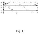
- Fig. 1 the control of the normal measuring operation M and on the other hand, the control of four different diagnostic functions D 1 , D 2 , D 3 and D 4 is shown schematically on the one hand.
- the normal measuring operation is interrupted regularly, wherein in the interruptions of the normal measuring operation successively the individual diagnostic functions are performed.
- the diagnostic functions are all repeated at the same frequency and that the respective interruption of the normal measuring operation for the individual diagnostic functions is always the same length.
- this is not absolutely necessary, but on the one hand, the repetition frequencies for the individual diagnostic functions and on the other hand, the respective durations of the interruptions of the normal measuring operation for the individual diagnostic functions may be different, namely adapted to the respective needs.
- the regular interruption of the normal measuring operation corresponds to the regular repetition, namely resumption of the normal measuring operation with a predetermined frequency f.
- the period T for the normal measuring operation is in the range between 1 and 100 s, while the duration ⁇ t for interrupting the normal measuring operation for performing a diagnostic function is only in the range of 10 to 200 ms lies.
- the ratios shown in FIG. 1 thus do not correspond to the actual chosen ratios of the durations.
- FIG. 2 shows diagrammatically a magnetic-inductive flowmeter. that with a flow control according to a preferred embodiment the invention is operated.
- the magnetic-inductive flowmeter has a measuring tube 1 through which a not further shown, electrically conductive medium flows.
- a substantially perpendicular to Flow direction of the medium extending magnetic field is using two magnetic coils 2, 3 generated.
- two measuring electrodes 4, 5 the are arranged such that their connecting line substantially perpendicular to the flow direction and perpendicular to the magnetic field direction, can the induced voltage can be tapped.
- a reference electrode 6 is provided, which is grounded.
- a power supply and measuring device. 7 provided with the two measuring electrodes 4, 5 with respect to a reference potential can be acted upon by an alternating current and the Impedance of the applied with the alternating current measuring electrode 4, 5 measured can be. For the sake of simplicity, however, this is only for the right measuring electrode 5 is shown.
- a solenoid coil 8 is provided by means of which the Solenoids 2, 3 are supplied with a predetermined field current.
- the solenoid coil 8 via the power supply and measuring device 7 detected induced voltage a linearity test of the magnetic-inductive flowmeter possible.
- a test current on the electrodes 4, 5 of the magneto-inductive Flowmeter and with respect to the linearity test by deliberately changing the field current of the field coils 2, 3 is explicitly on The prior art, namely to DE 101 18 002 A1 and the DE 100 64 738 A1.
- the two diagnostic functions - test current on the one hand and linearity test on the other hand - are now performed at such times, to which the normal Measuring operation of the magnetic inductive flowmeter interrupted becomes.
- An interruption of the normal measuring operation of the magnetic-inductive Flow meter takes place here in a time interval, which corresponds to a multiple of half the period of the magnetic field.
- a test current is alternately applied on the one hand and on the other hand performed the linearity test.
- the durations for each Interruptions essentially correspond to the periods of time required for the Performing the diagnostic functions are required. That means that the Diagnostic function immediately after interruption of normal measuring operation is recorded and the normal measurement operation then continued immediately when the diagnostic function is finished.
Abstract
Description
Die Erfindung betrifft ein Verfahren zum Betreiben eines Meßgeräts, wobei das Meßgerät mit einer Mehrzahl von Diagnosefunktionen versehen ist.The invention relates to a method for operating a measuring device, wherein the meter is provided with a plurality of diagnostic functions.
Aus dem Stand der Technik sind Meßgeräte, wie magnetisch-induktive Meßgeräte, bekannt, die mit verschiedenen Diagnosefunktionen versehen sind. Mit diesen Diagnosefunktionen soll der Betrieb der Meßgeräte geprüft werden, um deren Zuverlässigkeit zu verbessern. Bekannt sind dabei einerseits Diagnosefunktionen, die keinen Einfluß auf den Meßbetrieb haben, und andererseits solche, die den normalen Meßbetrieb stören, also nur bei ausgeschaltetem Meßbetrieb durchgeführt werden können.From the prior art are measuring devices, such as magnetic-inductive measuring devices, known, which are provided with various diagnostic functions. With These diagnostic functions should be used to check the operation of the measuring instruments in order to: to improve their reliability. On the one hand, diagnostic functions are known, which have no influence on the measuring operation, and on the other hand those that interfere with normal measuring operation, ie only when switched off Measuring operation can be performed.
Es ist die Aufgabe der Erfindung, ein Verfahren zum Betreiben eines Meßgeräts anzugeben, mit dem die angesprochenen Diagnosefunktionen einfach und effektiv durchgeführt werden können.It is the object of the invention to provide a method of operating a meter specify with which the mentioned diagnostic functions simple and can be done effectively.
Ausgehend von dem eingangs beschriebenen Verfahren zum Betreiben eines Meßgeräts ist die zuvor hergeleitete und aufgezeigte Aufgabe dadurch gelöst, daß eine derartige Ablaufsteuerung zur Durchführung der Diagnosefunktionen erfolgt, daß der normale Meßbetrieb des Meßgeräts unterbrochen wird, während der Unterbrechung des normalen Meßbetriebs eine erste Diagnosefunktion durchgeführt wird, der normale Meßbetrieb nach Durchführung der ersten Diagnosefunktion wieder aufgenommen wird, der normale Meßbetrieb des Meßgeräts wieder unterbrochen wird und während der Unterbrechung des normalen Meßbetriebs eine zweite Diagnosefunktion durchgeführt wird.Starting from the method described above for operating a Measuring device, the previously derived and indicated object is achieved by that such a sequence control for performing the diagnostic functions takes place that the normal measuring operation of the meter is interrupted while the interruption of the normal measuring operation, a first diagnostic function is performed, the normal measuring operation after performing the first Diagnostic function is resumed, the normal measuring operation of the Meter is interrupted again and during the interruption of the normal measuring operation, a second diagnostic function is performed.
Erfindungswesentlich ist also, daß der Betrieb des Meßgeräts zur Durchführung von Diagnosefunktionen einer Ablaufsteuerung unterworfen wird, nämlich derart, daß der normale Meßbetrieb unterbrochen wird und in diesen Unerbrechungen nacheinander voneinander verschiedene Diagnosefunktionen durchgeführt werden. Bei entsprechender Ausgestaltung der erfindungsgemäßen Ablaufsteuerung kann sichergestellt werden, daß sich unterschiedliche Diagnosefunktionen nicht gegenseitig stören oder beeinflussen und daß auch der normale Meßbetrieb durch die Diagnosefunktionen nicht in größerem Maße beeinträchtigt wird.Essential to the invention is therefore that the operation of the meter for performing of diagnostic functions is subjected to a flow control, namely such that the normal measuring operation is interrupted and in these interruptions consecutively different diagnostic functions be performed. With a corresponding embodiment of the invention Sequence control can be ensured that different Diagnostic functions do not interfere or affect one another and that too the normal measuring operation by the diagnostic functions not to a greater extent is impaired.
Gemäß einer bevorzugten Weiterbildung der Erfindung kann insbesondere vorgesehen sein, daß der normale Meßbetrieb nach Durchführung der zweiten Diagnosefunktion wieder aufgenommen wird, der normale Meßbetrieb des Meßgeräts wieder unterbrochen wird und während der Unterbrechung des normalen Meßbetriebs die erste Diagnosefunktion oder eine dritte Diagnosefunktion durchgeführt wird. Die verschiedenen Diagnosefunktionen können also nach unterschiedlichen Zeiten wiederholt werden, so daß insgesamt grundsätzlich eine beliebige Anzahl von Diagnosefunktionen in die erfindungsgemäße Ablaufsteuerung integriert werden kann.According to a preferred embodiment of the invention may in particular be provided that the normal measuring operation after carrying out the second Diagnostic function is resumed, the normal measuring operation of the Meter is interrupted again and during the interruption of the normal measuring operation, the first diagnostic function or a third diagnostic function is carried out. The various diagnostic functions can so be repeated after different times, so that in total basically any number of diagnostic functions in the invention Flow control can be integrated.
Die Wiederholung von Diagnosefunktionen ist grundsätzlich beliebig, muß insbesondere nämlich auch nicht periodisch sein. Ist jedoch eine sich periodisch wiederholende Durchführung der Diagnosefunktion vorgesehen, so können grundsätzlich alle Diagnosefunktionen mit der selben Frequenz wiederholt werden. Gemäß einer bevorzugten Weiterbildung der Erfindung ist jedoch vorgesehen, daß die einzelnen Diagnosefunktionen mit unterschiedlichen Frequenzen periodisch wiederholt werden. Auf diese Weise können besonders wichtige Diagnosefunktionen öfter wiederholt werden. Dabei kann einerseits vorgesehen sein, daß die Wiederholfrequenz für die Diagnosefunktionen voreingestellt ist. Andererseits kann die Wiederholfrequenz für die Diagnosefunktionen aber auch vom Verwender des Meßgeräts einstellbar sein.The repetition of diagnostic functions is basically arbitrary namely in particular not be periodic. However, one is periodic Repeated execution of the diagnostic function provided, so In principle all diagnostic functions can be repeated with the same frequency become. However, according to a preferred embodiment of the invention provided that the individual diagnostic functions with different Frequencies are repeated periodically. This way can be special important diagnostic functions are repeated more often. It can on the one hand be provided that the repetition frequency for the diagnostic functions preset is. On the other hand, the refresh rate for the diagnostic functions but also be adjustable by the user of the meter.
Grundsätzlich kann die jeweilige Dauer der Unterbrechung des normalen Meßbetriebs für alle Diagnosefunktionen gleich sein. Gemäß einer bevorzugten Weiterbildung der Erfindung ist jedoch vorgesehen, daß die jeweilige Dauer der Unterbrechung des normalen Meßbetriebs in Abhängigkeit von der Art der durchgeführten Diagnosefunktion gesteuert wird. Die Unterbrechungen des normalen Meßbetriebs müssen also nicht für alle Diagnosefunktionen gleich lang sein, so daß z. B. sehr schnell durchzuführende Diagnosefunktionen auch nur mit einer sehr kurzen Unterbrechung des normalen Meßbetriebs einhergehen. Insbesondere ist gemäß einer bevorzugten Weiterbildung der Erfindung vorgesehen, daß die jeweilige Dauer der Unterbrechung des normalen Meßbetriebs im Bereich von 10 bis 200 ms gesteuert wird. Weiterhin ist gemäß einer bevorzugten Weiterbildung der Erfindung vorgesehen, daß der zeitliche Abstand zwischen zwei Unterbrechungen des normalen Meßbetriebs im Bereich von 1 bis 100 s gesteuert wird.Basically, the respective duration of the interruption of the normal Measuring mode for all diagnostic functions to be the same. According to a preferred Development of the invention, however, is provided that the respective Duration of interruption of the normal measuring operation as a function of the Type of diagnostic function performed is controlled. The interruptions of the normal measuring operation must therefore not for all diagnostic functions be the same length, so that z. B. very quickly performed diagnostic functions also only with a very short interruption of the normal measuring operation accompanied. In particular, according to a preferred embodiment of the invention provided that the respective duration of the interruption of the normal Measuring operation is controlled in the range of 10 to 200 ms. Furthermore, according to a preferred embodiment of the invention provided that the time interval between two interruptions of the normal measuring operation is controlled in the range of 1 to 100 s.
Während der Unterbrechung des normalen Meßbetriebs kann grundsätzlich vorgesehen sein, daß kein Meßwert ausgegeben wird. Gemäß einer bevorzugten Weiterbildung der Erfindung ist jedoch vorgesehen, daß während einer Unterbrechung des normalen Meßbetriebs als Meßwert der zuletzt ermittelte Meßwert ausgegeben wird. Alternativ dazu ist gemäß einer bevorzugten Weiterbildung der Erfindung vorgesehen, daß während einer Unterbrechung des normalen Meßbetriebs ein Hilfsmeßbetrieb erfolgt, im Rahmen dessen ein Meßwert mit geringerer Genauigkeit ermittelt und ausgegeben wird.During the interruption of the normal measuring operation can basically be provided that no measured value is output. According to a preferred Development of the invention, however, is provided that during a Interruption of the normal measuring operation as measured value of the last determined Measured value is output. Alternatively, according to a preferred embodiment the invention provided that during an interruption of normal Meßbetriebs a Hilfsmeßbetrieb takes place in the context of a Measured value with lower accuracy is determined and output.
Bezüglich dieses Hilfsmeßbetriebs kann z. B. vorgesehen sein, daß für den eigentlichen Meßbetrieb weniger Leistung zur Verfügung steht, was mit einem geringeren Signal und damit einem verschlechterten Signal-zu-Rausch-Verhältnis einhergeht. Andererseits kann es während des Hilfsmeßbetriebs, zu dem parallel ja die Diagnosefunktion durchgeführt wird, zu einer Beeinflussung des Meßwerts durch die Diagnosefunktion kommen.With regard to this Hilfsmeßbetriebs z. B. be provided that for the actual Measuring operation less power is available, what with one lower signal and thus a deteriorated signal-to-noise ratio accompanied. On the other hand, during the auxiliary measuring operation, too the parallel yes the diagnostic function is performed, to an influence of the measured value come through the diagnostic function.
Insbesondere ist in diesem Zusammenhang gemäß einer bevorzugten Weiterbildung der Erfindung vorgesehen, daß die Einleitung eines Hilfsmeßbetriebs während einer Unterbrechung des normalen Meßbetriebs in Abhängigkeit von der Art der Diagnosefunktion gesteuert wird. Diese Ausgestaltung des Verfahrens trägt dem Rechnung, daß manche Diagnosefunktionen aufgrund ihrer Wechselwirkung mit Einrichtungen des Meßgeräts jegliche Art von Meßbetrieb und damit auch einen Hilfsmeßbetrieb ausschließen. Um damit jedoch nicht gänzlich auf einen Hilfsmeßbetrieb während der Unterbrechungen des normalen Meßbetriebs verzichten zu müssen, wird bei solchen Diagnosefunktionen, die grundsätzlich einen Meßbetrieb zulassen, individuell ein Hilfsmeßbetrieb gestartet.In particular, in this context according to a preferred embodiment the invention provided that the initiation of a Hilfsmeßbetriebs during an interruption of the normal measuring operation in dependence on the type of diagnostic function is controlled. This embodiment of the method takes into account that some diagnostic functions due to their Interaction with equipment of the meter any kind of measuring operation and thus exclude an auxiliary measuring operation. But with it not entirely on an auxiliary measuring operation during the interruptions of the having to forego normal measuring operation, in such diagnostic functions, which basically allow a measuring operation, individually a Hilfsmeßbetrieb started.
Die Ergebnisse der einzelnen Diagnosefunktionen, also die dabei ermittelten Werte, können direkt ausgegeben werden. Gemäß einer bevorzugten Weiterbildung der Erfindung ist jedoch vorgesehen, daß die Ergebnisse der einzelnen Diagnosefunktionen zeitlich gemittelt werden. Auf diese Weise sind nur kurze Unterbrechungen des normalen Meßbetriebs erforderlich, und es wird die Verläßlichkeit der ermittelten Diagnosewerte erhöht. Dabei können Diagnosefunktionen, die mehrere Mittelungen erfordern, öfter wiederholt werden als andere.The results of the individual diagnostic functions, ie the ones determined Values can be output directly. According to a preferred embodiment However, the invention provides that the results of the individual Diagnostic functions are averaged over time. In this way are only short Interruptions of the normal measuring operation required, and it will be the Reliability of the determined diagnostic values increased. In doing so, diagnostic functions, which require multiple averagings, are repeated more often than other.
Schließlich ist gemäß einer bevorzugten Weiterbildung der Erfindung vorgesehen, daß die gesamte Ablaufsteuerung insgesamt periodisch wiederholt wird. Im übrigen kann die ganze Ablaufsteuerung, also alle Diagnosefunktionen, deaktivierbar sein, wobei auch vorgesehen sein kann, daß nur einzelne Diagnosefunktionen deaktiviert werden. Dies kann einerseits vom Verwender selbst, typischerweise direkt am Meßgerät, oder über einen Steuereingang elektronisch durch ein Leitsystem erfolgen.Finally, according to a preferred embodiment of the invention, that the entire sequence control repeats periodically becomes. Incidentally, the entire process control, ie all diagnostic functions, be deactivated, which can also be provided that only individual Diagnostic functions are disabled. This can on the one hand by the user itself, typically directly at the meter, or via a control input done electronically by a control system.
Gemäß einer bevorzugten Weiterbildung der Erfindung ist die Verwendung des zuvor beschriebenen Verfahrens insbesondere für ein magnetisch-induktives Durchflußmeßgerät vorgesehen. Magnetisch-induktive Durchflußmeßgeräte sind aus dem Stand der Technik gut bekannt und weisen typischerweise ein von einem strömenden Medium durchflossenes Meßrohr, zwei entlang einer zumindest im wesentlich senkrecht zur Meßrohrachse verlaufenden Verbindungslinie angeordnete Meßelektroden und zwar ein zumindest im wesentlichen senkrecht zur Meßrohrachse und senkrecht zur Verbindungslinie der Meßelektroden verlaufendes Magnetfeld erzeugende Magnetspulen auf. Zur Bestimmung des Durchflusses des strömenden Mediums durch das Meßrohr wird an einer oder an beiden Meßelektroden jeweils eine Spannung gegenüber einem Referenzpotential abgegriffen.According to a preferred embodiment of the invention, the use of the method described above, in particular for a magneto-inductive Flow meter provided. Magnetic-inductive flowmeters are well known in the art and typically are a flowed through by a flowing medium measuring tube, two along a running at least substantially perpendicular to Meßrohrachse Connecting line arranged measuring electrodes and that at least in essentially perpendicular to the measuring tube axis and perpendicular to the connecting line the measuring electrodes extending magnetic field generating magnetic coils. To determine the flow of the flowing medium through the measuring tube In each case a voltage is compared with one or both measuring electrodes a reference potential.
Das Prinzip des magnetisch-induktiven Durchflußmeßverfahrens beruht auf der elektrodynamischen Induktion: Nach dem Faraday'schen Induktionsgesetz entsteht in einem strömenden Medium, das Ladungsträger mit sich führt und durch ein Magnetfeld hindurchfließt, eine elektrische Feldstärke senkrecht zur Strömungsrichtung und senkrecht zum Magnetfeld. Innerhalb des Magnetfelds liefert jedes sich durch das Magnetfeld bewegende und eine gewisse Anzahl von Ladungsträgern aufweisende Volumenelement des strömenden Mediums mit der in diesem Volumenelement entstehenden Feldstärke einen Beitrag zu einer über die Meßelektroden abgreifbaren Meßspannung. The principle of the magnetic-inductive flow measurement is based on of electrodynamic induction: According to Faraday's law of induction arises in a flowing medium that carries charge carriers with it and passing through a magnetic field, an electric field strength perpendicular to Flow direction and perpendicular to the magnetic field. Within the magnetic field each one moves through the magnetic field and delivers a certain number Volume element of the flowing medium having charge carriers contributing to the field strength arising in this volume element a tapped over the measuring electrodes measuring voltage.
Im eigentlichen Durchflußmeßbetrieb wird bei einem magnetisch-induktiven Durchflußmeßgerät im allgemeinen das Magnetfeld zeitlich alternierend umgeschaltet. Dazu sind unterschiedliche Vorgehensweisen bekannt, wie die Verwendung eines Wechselfelds oder eines geschalteten Gleichfelds. Möglich ist auch die Verwendung eines pulsierenden Gleichfelds, das dadurch erhalten wird, daß die Magnetspulen des Magneten nur periodenweise mit einem zeitlich rechteckförmigen, immer die gleiche Polarität aufweisenden Strom versorgt werden. Ein Verfahren, bei dem der Feldstrom periodisch umgepolt wird, ist jedoch bevorzugt, da durch die Änderung der Polarität des Magnetfelds Störgrößen, wie elektrochemische Störgrößen, unterdrückt werden können.In actual flow measurement is in a magnetic-inductive Flow meter generally alternately temporally switching the magnetic field. For this purpose, different approaches are known, such as Using an alternating field or a switched dc field. Possible is also the use of a pulsating DC field obtained by it is that the magnetic coils of the magnet only periodically with a time supplied rectangular, always having the same polarity current become. A method in which the field current is periodically reversed However, it is preferred because of the change in the polarity of the magnetic field Disturbing variables, such as electrochemical disturbances, can be suppressed.
Bei magnetisch-induktiven Durchflußmeßgeräten kann es nun zu einer Vielzahl von Störungen kommen, die einen verläßlichen Meßbetrieb negativ beeinflussen können. Als ein Beispiel sei nur genannt, daß sich auf in galvanisch leitendem Kontakt mit dem strömenden Medium stehenden Elektroden Abscheidungen aus dem Medium absetzen können, so daß es zu belegten Elektroden kommt, die das Meßergebnis verfälschen.In magnetic-inductive flowmeters, it can now be a variety come from disturbances that negatively affect a reliable measuring operation can. As an example let me just mention that in on galvanic conductive contact with the flowing medium electrode electrode deposits can settle out of the medium, so that it is too occupied electrodes comes, which distort the measurement result.
Bei einem solchen magnetisch-induktiven Durchflußmeßgerät können nun als Diagnosefunktionen, die, wie oben beschrieben, einer erfindungsgemäßen Ablaufsteuerung unterworfen werden, unter anderem folgende Funktionen vorgesehen sein: eine Elektrodenimpedanzmessung durch einen Teststrom auf die Elektroden des magnetisch-induktiven Durchflußmeßgeräts, eine Linearitätsprüfung durch gezielte Änderung des Feldstroms, eine Addition eines bekannten Testsignals zu dem normalen Elektrodensignal zur Kontrolle der Vorverstärkung oder/und der A/D-Wandlung und die Erzeugung eines inhomogenen Magnetfelds. Dazu sei angemerkt, daß die Erzeugung eines inhomogenen Magnetfelds z. B. durch einander gegenüberliegende, gegensinnig stromdurchflossene Magnetspulen erzielt werden kann.In such a magnetic-inductive flowmeter can now as Diagnostic functions which, as described above, an inventive Sequential control are subjected to, inter alia, the following functions be provided: an electrode impedance measurement by a test current the electrodes of the magnetic inductive flowmeter, a linearity test by deliberately changing the field current, an addition of a known Test signal to the normal electrode signal to control the Pre-amplification and / or A / D conversion and the generation of an inhomogeneous Magnetic field. It should be noted that the generation of an inhomogeneous Magnetic field z. B. by opposing, in opposite directions current-carrying magnetic coils can be achieved.
Bei der Verwendung der erfindungsgemäßen Ablaufsteuerung für ein magnetisch-induktives Durchflußmeßgerät kann bezüglich der zeitlichen Steuerung gemäß einer bevorzugten Weiterbildung der Erfindung insbesondere vorgesehen sein, daß der zeitliche Abstand zwischen zwei Unterbrechungen des normalen Meßbetriebs des magnetisch-induktiven Durchflußmeßgeräts derart gesteuert wird, daß der zeitliche Abstand einem Vielfachen der halben Periodendauer des Magnetfelds entspricht.When using the sequence control for a magneto-inductive Flow meter can with respect to the timing provided in particular according to a preferred embodiment of the invention be that the time interval between two interruptions of the normal Controlled measuring operation of the magnetic inductive flowmeter so is that the time interval is a multiple of half the period corresponds to the magnetic field.
Im einzelnen gibt es nun eine Vielzahl von Möglichkeiten, das erfindungsgemäße Verfahren auszugestalten und weiterzubilden. Dazu wird auf die dem Patentanspruch 1 nachgeordneten Patentansprüche sowie auf die nachfolgende Beschreibung eines bevorzugten Ausführungsbeispiels der Erfindung unter Bezugnahme auf die Zeichnung verwiesen. In der Zeichnung zeigt
- Fig. 1
- schematisch eine Ablaufsteuerung gemäß einem bevorzugten Ausführungsbeispiel der Erfindung und
- Fig. 2
- schematisch ein magnetisch-induktives Durchflußmeßgerät, das mit einer Ablaufsteuerung gemäß einem bevorzugten Ausführungsbeispiel der Erfindung betrieben wird.
- Fig. 1
- schematically a flow control according to a preferred embodiment of the invention and
- Fig. 2
- schematically a magnetic-inductive flow meter, which is operated with a flow control according to a preferred embodiment of the invention.
In Fig. 1 ist schematisch einerseits die Steuerung des normalen Meßbetriebs M und andererseits die Steuerung von vier unterschiedlichen Diagnosefunktionen D1, D2, D3 und D4 dargestellt. Der normale Meßbetrieb wird regelmäßig unterbrochen, wobei in den Unterbrechungen des normalen Meßbetriebs nacheinander die einzelnen Diagnosefunktionen durchgeführt werden. Vorliegend ist dargestellt, daß die Diagnosefunktionen alle mit der gleichen Frequenz wiederholt werden und daß die jeweilige Unterbrechung des normalen Meßbetriebs für die einzelnen Diagnosefunktionen immer gleich lang ist. Wie weiter oben schon ausgeführt, ist dies jedoch nicht zwingend erforderlich, vielmehr können einerseits die Wiederholfrequenzen für die einzelnen Diagnosefunktionen und andererseits die jeweiligen Dauern der Unterbrechungen des normalen Meßbetriebs für die einzelnen Diagnosefunktionen unterschiedlich sein, nämlich an den jeweiligen Bedarf angepaßt sein.In Fig. 1, the control of the normal measuring operation M and on the other hand, the control of four different diagnostic functions D 1 , D 2 , D 3 and D 4 is shown schematically on the one hand. The normal measuring operation is interrupted regularly, wherein in the interruptions of the normal measuring operation successively the individual diagnostic functions are performed. In the present case it is shown that the diagnostic functions are all repeated at the same frequency and that the respective interruption of the normal measuring operation for the individual diagnostic functions is always the same length. However, as stated above, this is not absolutely necessary, but on the one hand, the repetition frequencies for the individual diagnostic functions and on the other hand, the respective durations of the interruptions of the normal measuring operation for the individual diagnostic functions may be different, namely adapted to the respective needs.
Die regelmäßige Unterbrechung des normalen Meßbetriebs entspricht der regelmäßigen Wiederholung, nämlich Wiederaufnahme, des normalen Meßbetriebs mit einer vorbestimmten Frequenz f. Dieser Frequenz f entspricht die Periodendauer T = 1/f, wobei vorliegend vorgesehen ist, daß die Periodendauer T wesentlich größer ist als die jeweilige Dauer Δt der Unterbrechung des Meßbetriebs für die Durchführung einer Diagnosefunktion. Konkret gilt bei dem hier beschriebenen bevorzugten Ausführungsbeispiel der Erfindung, daß die Periodendauer T für den normalen Meßbetrieb im Bereich zwischen 1 und 100 s liegt, während die Dauer Δt der Unterbrechung des normalen Meßbetriebs für die Durchführung einer Diagnosefunktion lediglich im Bereich von 10 bis 200 ms liegt. Die in Fig. 1 gezeigten Verhältnisse entsprechen also nicht den tatsächlich gewählten Verhältnissen der Zeitdauern.The regular interruption of the normal measuring operation corresponds to the regular repetition, namely resumption of the normal measuring operation with a predetermined frequency f. This frequency f corresponds to the period T = 1 / f , wherein it is provided in this case that the period T is substantially greater than the respective duration .DELTA.t the interruption of the measuring operation for the implementation of a diagnostic function. Specifically, in the preferred embodiment of the invention described here, the period T for the normal measuring operation is in the range between 1 and 100 s, while the duration Δt for interrupting the normal measuring operation for performing a diagnostic function is only in the range of 10 to 200 ms lies. The ratios shown in FIG. 1 thus do not correspond to the actual chosen ratios of the durations.
Aus Fig. 2 ist schematisch ein magnetisch-induktives Durchflußmeßgerät ersichtlich,
daß mit einer Ablaufsteuerung gemäß einem bevorzugten Ausführungsbeispiel
der Erfindung betrieben wird. Das magnetisch-induktive Durchflußmeßgerät
weist ein Meßrohr 1 auf, durch das ein nicht weiter dargestelltes,
elektrisch leitfähiges Medium strömt. Ein im wesentlichen senkrecht zur
Durchflußrichtung des Mediums verlaufendes Magnetfeld wird mit Hilfe von
zwei Magnetspulen 2, 3 erzeugt. Mit Hilfe von zwei Meßelektroden 4, 5, die
derart angeordnet sind, daß ihre Verbindungslinie im wesentlichen senkrecht
zur Durchflußrichtung und senkrecht zur Magnetfeldrichtung verläuft, kann
die induzierte Spannung abgegriffen werden. Darüber hinaus ist eine Referenzelektrode
6 vorgesehen, die geerdet ist.FIG. 2 shows diagrammatically a magnetic-inductive flowmeter.
that with a flow control according to a preferred embodiment
the invention is operated. The magnetic-inductive flowmeter
has a measuring tube 1 through which a not further shown,
electrically conductive medium flows. A substantially perpendicular to
Flow direction of the medium extending magnetic field is using
two
Bei dem in Fig. 2 gezeigten magnetisch-induktiven Durchflußmeßgerät sind
zwei Diagnosefunktionen implementiert, nämlich einerseits das Anlegen eines
Teststroms auf die Elektroden 4, 5 und andererseits eine Linearitätsprüfung
durch gezielte Änderung des durch die Magnetspulen 2, 3 fließenden Feldstroms.
Dazu ist einerseits eine Stromversorgungs- und Meßeinrichtung 7
vorgesehen, mit der die beiden Meßelektroden 4, 5 gegenüber einem Referenzpotential
mit einem Wechselstrom beaufschlagt werden können und die
Impedanz der mit dem Wechselstrom beaufschlagten Meßelektrode 4, 5 gemessen
werden kann. Der Einfachheit halber ist dies jedoch lediglich für die
rechte Meßelektrode 5 dargestellt.In the magneto-inductive flowmeter shown in Fig. 2 are
implemented two diagnostic functions, namely on the one hand the creation of a
Test current to the
Außerdem ist eine Magnetspulenversorgung 8 vorgesehen, mittels derer die
Magnetspulen 2, 3 mit einem vorbestimmten Feldstrom versorgt werden.
Durch Erhöhung des Feldstroms um einen vorbestimmten Faktor wird auch
das Magnetfeld um diesen Faktor erhöht, was seinerseits eine Erhöhung der
induzierten Spannung ebenfalls um diesen Faktor erwarten läßt. Auf diese
Weise ist mit Hilfe der Magnetspulenversorgung 8 über die von der Stromversorgungs-
und Meßeinrichtung 7 erfaßte induzierte Spannung eine Linearitätsprüfung
des magnetisch-induktiven Durchflußmeßgeräts möglich. Bezüglich
der Verwendung eines Teststroms auf der Elektroden 4, 5 des magnetisch-induktiven
Durchflußmeßgeräts und bezüglich der Linearitätsprüfung
durch gezielte Änderung des Feldstroms der Feldspulen 2, 3 wird explizit auf
den Stand der Technik verwiesen, nämlich auf die DE 101 18 002 A1 und die
DE 100 64 738 A1.In addition, a
Die beiden Diagnosefunktionen ― Teststrom einerseits und Linearitätsprüfung andererseits ― werden nun zu solchen Zeiten durchgeführt, zu denen der normale Meßbetrieb des magnetisch-induktiven Durchflußmeßgeräts unterbrochen wird. Eine Unterbrechung des normalen Meßbetriebs des magnetisch-induktiven Durchflußmeßgeräts erfolgt vorliegend in einem zeitlichen Abstand, der einem Vielfachen der halben Periodendauer des Magnetfelds entspricht. Dabei wird abwechselnd einerseits ein Teststrom angelegt und andererseits die Linearitätsprüfung durchgeführt. Die Zeitdauern für die jeweiligen Unterbrechungen entsprechen im wesentlichen den Zeitdauern, die für die Durchführung der Diagnosefunktionen erforderlich sind. Das heißt, daß die Diagnosefunktion umgehend nach Unterbrechung des normalen Meßbetriebs aufgenommen wird und der normale Meßbetrieb umgehend dann fortgesetzt wird, wenn die Diagnosefunktion beendet ist.The two diagnostic functions - test current on the one hand and linearity test on the other hand - are now performed at such times, to which the normal Measuring operation of the magnetic inductive flowmeter interrupted becomes. An interruption of the normal measuring operation of the magnetic-inductive Flow meter takes place here in a time interval, which corresponds to a multiple of half the period of the magnetic field. In this case, a test current is alternately applied on the one hand and on the other hand performed the linearity test. The durations for each Interruptions essentially correspond to the periods of time required for the Performing the diagnostic functions are required. That means that the Diagnostic function immediately after interruption of normal measuring operation is recorded and the normal measurement operation then continued immediately when the diagnostic function is finished.
Die entsprechende Ablaufsteuerung wird gemäß dem vorliegend beschriebenen
bevorzugten Ausführungsbeispiel der Erfindung von einer Ablaufsteuerund
Auswerteeinrichtung 9 übernommen. Dieser werden auch die Ergebnisse
der Diagnosefunktionen zugeführt, so daß dort eine zeitliche Mittelung der
Ergebnisse erfolgen kann bevor diese Ergebnisse über eine Ausgabeeinrichtung
10, wie eine Anzeige- oder eine Busschnittstelle, ausgegeben werden. Im
Ergebnis werden damit die Diagnosefunktionen auf einfache und effiziente
Weise in den Betrieb des magnetisch-induktiven Durchflußmeßgeräts integriert,
ohne den normalen Meßbetrieb in größerem Umfang zu beeinträchtigen.The corresponding sequence control will be described in accordance with the present invention
preferred embodiment of the invention of a
Claims (13)
Applications Claiming Priority (2)
| Application Number | Priority Date | Filing Date | Title |
|---|---|---|---|
| DE10356008A DE10356008B4 (en) | 2003-11-27 | 2003-11-27 | Method for operating a measuring device |
| DE10356008 | 2003-11-27 |
Publications (2)
| Publication Number | Publication Date |
|---|---|
| EP1536210A2 true EP1536210A2 (en) | 2005-06-01 |
| EP1536210A3 EP1536210A3 (en) | 2009-04-01 |
Family
ID=34442374
Family Applications (1)
| Application Number | Title | Priority Date | Filing Date |
|---|---|---|---|
| EP04024764A Ceased EP1536210A3 (en) | 2003-11-27 | 2004-10-18 | Method of operating a measuring apparatus |
Country Status (7)
| Country | Link |
|---|---|
| US (1) | US7171336B2 (en) |
| EP (1) | EP1536210A3 (en) |
| JP (1) | JP4908752B2 (en) |
| CN (1) | CN100371687C (en) |
| CA (1) | CA2488471C (en) |
| DE (1) | DE10356008B4 (en) |
| NO (1) | NO340733B1 (en) |
Families Citing this family (12)
| Publication number | Priority date | Publication date | Assignee | Title |
|---|---|---|---|---|
| DE102005018179A1 (en) * | 2005-04-19 | 2006-10-26 | Krohne Messtechnik Gmbh & Co. Kg | Method for operating a measuring device |
| JP5998504B2 (en) * | 2012-02-08 | 2016-09-28 | 横河電機株式会社 | Flow meter and flow meter diagnostic method |
| DE102012016404B4 (en) * | 2012-08-21 | 2021-08-05 | Krohne Ag | Magnetic-inductive flow meter with a plurality of functional units |
| DE102014007426B4 (en) * | 2013-07-01 | 2022-07-07 | Krohne Messtechnik Gmbh | Electromagnetic flow measuring device and method for operating a magnetic inductive flow measuring device |
| JP6135924B2 (en) * | 2013-07-08 | 2017-05-31 | 横河電機株式会社 | Electromagnetic flow meter |
| US10663331B2 (en) * | 2013-09-26 | 2020-05-26 | Rosemount Inc. | Magnetic flowmeter with power limit and over-current detection |
| DE102014004122B3 (en) | 2014-03-24 | 2015-08-06 | Krohne Messtechnik Gmbh | Magnetic-inductive flowmeter and method for operating a magnetic-inductive flowmeter |
| GB2544286A (en) * | 2015-11-10 | 2017-05-17 | Abb Ltd | Method and apparatus for electrode impedance measurement |
| CN109297523A (en) * | 2018-10-11 | 2019-02-01 | 中车青岛四方机车车辆股份有限公司 | A kind of absolute fix sensor detecting system |
| NO20190208A1 (en) * | 2019-02-14 | 2020-08-17 | Roxar Flow Measurement As | Impedance layer estimation |
| DE102019107904B3 (en) * | 2019-03-27 | 2020-08-13 | Krohne Messtechnik Gmbh | Electromagnetic flow meter with conductivity measuring device and method for operating a magnetic inductive flow measuring device with conductivity measuring device |
| CN112461305B (en) * | 2020-11-16 | 2022-04-29 | 西南石油大学 | Multi-coil array flow electromagnetic measurement device and measurement method |
Citations (3)
| Publication number | Priority date | Publication date | Assignee | Title |
|---|---|---|---|---|
| US4676112A (en) * | 1985-03-08 | 1987-06-30 | Hitachi, Ltd. | Electromagnetic flow meter |
| EP0521448A2 (en) * | 1991-07-04 | 1993-01-07 | Fischer & Porter GmbH | Circuit for the determination of errors in a magnetic-inductive flowmeter arrangement |
| WO2001001079A1 (en) * | 1999-06-30 | 2001-01-04 | General Electric Company | Methods and apparatus for meter i/o board addressing and communication |
Family Cites Families (12)
| Publication number | Priority date | Publication date | Assignee | Title |
|---|---|---|---|---|
| CH678978A5 (en) * | 1989-09-29 | 1991-11-29 | Mettler Toledo Ag | |
| KR910020404A (en) | 1990-05-11 | 1991-12-20 | 강진구 | Refrigerator with self diagnostic function |
| DE4027803A1 (en) * | 1990-09-01 | 1992-03-05 | Abb Patent Gmbh | MULTIMETER WITH A MEASURING RANGE SWITCH |
| DE9205313U1 (en) * | 1992-04-16 | 1992-07-30 | Conducta Gesellschaft Fuer Mess- Und Regeltechnik Mbh & Co, 7016 Gerlingen, De | |
| US20020186000A1 (en) * | 1993-03-26 | 2002-12-12 | Briese Forrest Wayne | Electronic revenue meter with automatic service sensing |
| JPH08241185A (en) * | 1994-11-03 | 1996-09-17 | Motorola Inc | Integrated testing and measuring means as well as method foradoption of graphical user interface |
| GB9703066D0 (en) * | 1997-02-14 | 1997-04-02 | Schlumberger Ind Ltd | EMS testing system |
| DE19756081A1 (en) * | 1997-12-17 | 1999-06-24 | Bosch Gmbh Robert | Monitoring and fault detection procedures |
| CN2353080Y (en) * | 1998-07-27 | 1999-12-08 | 机械工业部北京机电研究所 | Controller for battery charbing arrangement for electric automobile in public place |
| DE10064738B4 (en) * | 2000-12-22 | 2004-02-12 | Krohne Meßtechnik GmbH & Co KG | Method for testing a magnetic-inductive flow meter |
| DE10118002B4 (en) * | 2001-04-10 | 2004-12-30 | Krohne Meßtechnik GmbH & Co KG | Magnetic-inductive flow measuring method and magnetic-inductive flow meter |
| US6639669B2 (en) * | 2001-09-10 | 2003-10-28 | Xerox Corporation | Diagnostics for color printer on-line spectrophotometer control system |
-
2003
- 2003-11-27 DE DE10356008A patent/DE10356008B4/en not_active Expired - Fee Related
-
2004
- 2004-10-18 EP EP04024764A patent/EP1536210A3/en not_active Ceased
- 2004-11-25 NO NO20045176A patent/NO340733B1/en not_active IP Right Cessation
- 2004-11-25 CA CA002488471A patent/CA2488471C/en not_active Expired - Fee Related
- 2004-11-26 JP JP2004343009A patent/JP4908752B2/en not_active Expired - Fee Related
- 2004-11-26 CN CNB2004100958801A patent/CN100371687C/en not_active Expired - Fee Related
- 2004-11-29 US US10/998,431 patent/US7171336B2/en not_active Expired - Fee Related
Patent Citations (3)
| Publication number | Priority date | Publication date | Assignee | Title |
|---|---|---|---|---|
| US4676112A (en) * | 1985-03-08 | 1987-06-30 | Hitachi, Ltd. | Electromagnetic flow meter |
| EP0521448A2 (en) * | 1991-07-04 | 1993-01-07 | Fischer & Porter GmbH | Circuit for the determination of errors in a magnetic-inductive flowmeter arrangement |
| WO2001001079A1 (en) * | 1999-06-30 | 2001-01-04 | General Electric Company | Methods and apparatus for meter i/o board addressing and communication |
Also Published As
| Publication number | Publication date |
|---|---|
| CA2488471C (en) | 2009-07-07 |
| CA2488471A1 (en) | 2005-05-27 |
| DE10356008B4 (en) | 2010-04-08 |
| NO20045176L (en) | 2005-05-30 |
| EP1536210A3 (en) | 2009-04-01 |
| CN100371687C (en) | 2008-02-27 |
| US7171336B2 (en) | 2007-01-30 |
| NO340733B1 (en) | 2017-06-06 |
| JP4908752B2 (en) | 2012-04-04 |
| US20060116854A1 (en) | 2006-06-01 |
| CN1621782A (en) | 2005-06-01 |
| JP2005156567A (en) | 2005-06-16 |
| DE10356008A1 (en) | 2005-07-07 |
Similar Documents
| Publication | Publication Date | Title |
|---|---|---|
| EP1536211B1 (en) | Method for operating a magnetic inductive flowmeter | |
| EP1584902B1 (en) | Electromagnetic flowmeter and method for operating an electromagnetic flowmeter | |
| EP1217337A2 (en) | Method for testing the functioning of a flow measurement device | |
| EP2821756B1 (en) | Magnetic-inductive flow measuring apparatus and method for operating a magnetic-inductive flow measuring apparatus | |
| EP1536210A2 (en) | Method of operating a measuring apparatus | |
| EP4078100B1 (en) | Method of operating a magnetic inductive flowmeter | |
| EP1715301A2 (en) | Method for operating a measuring device | |
| DE102004057680A1 (en) | Magnetically inductive flow rate sensor function monitoring method for industry, involves monitoring sensor function based on receive signal induced by temporally changing magnetic field in coil serving as receiver | |
| DE10118002B4 (en) | Magnetic-inductive flow measuring method and magnetic-inductive flow meter | |
| EP2568262A1 (en) | Method for operating multiple neighbouring magnetic-inductive flow meters | |
| EP1431716A1 (en) | Electromagnetic flowmeter | |
| EP1079212B1 (en) | Method for the magnetic-inductive measurement of fluid flow | |
| DE2846538A1 (en) | HEAT METER | |
| DE102016124976A1 (en) | Method for operating a magnetic-inductive flowmeter and such a flowmeter | |
| DE10312058A1 (en) | Device for measuring the volume flow of a measuring medium in a measuring tube | |
| DE10357514B3 (en) | Magnetic-inductive volumetric flowmeter using detection of voltage induced in flow medium by magnetic field in measuring pipe with control circuit for controlling potential of reference electrode | |
| DE102016124977B4 (en) | Method for operating a magnetic-inductive flow measuring device and such a flow measuring device | |
| EP1363108A2 (en) | Method to determine the uncertainty of a magnetic inductive flow meter | |
| DE10317456B4 (en) | Method for operating a magneto-inductive flowmeter | |
| DE102021127230B3 (en) | Electromagnetic flow measuring device and method for operating such a device | |
| DE10356009B4 (en) | Magnetic-inductive flowmeter and method for operating a magnetic-inductive flowmeter | |
| EP1273891A1 (en) | Method for driving an electromagnetic flowmeter | |
| EP1273892A1 (en) | Method for activating an electromagnetic flowmeter | |
| DE102021105516B3 (en) | Method for determining a conductivity, operating method of a magnetic-inductive flowmeter and magnetic-inductive flowmeter | |
| EP1348936A1 (en) | Magnetic inductive flow measuring method |
Legal Events
| Date | Code | Title | Description |
|---|---|---|---|
| PUAI | Public reference made under article 153(3) epc to a published international application that has entered the european phase |
Free format text: ORIGINAL CODE: 0009012 |
|
| AK | Designated contracting states |
Kind code of ref document: A2 Designated state(s): AT BE BG CH CY CZ DE DK EE ES FI FR GB GR HU IE IT LI LU MC NL PL PT RO SE SI SK TR |
|
| AX | Request for extension of the european patent |
Extension state: AL HR LT LV MK |
|
| PUAL | Search report despatched |
Free format text: ORIGINAL CODE: 0009013 |
|
| AK | Designated contracting states |
Kind code of ref document: A3 Designated state(s): AT BE BG CH CY CZ DE DK EE ES FI FR GB GR HU IE IT LI LU MC NL PL PT RO SE SI SK TR |
|
| AX | Request for extension of the european patent |
Extension state: AL HR LT LV MK |
|
| 17P | Request for examination filed |
Effective date: 20090925 |
|
| AKX | Designation fees paid |
Designated state(s): AT BE BG CH CY CZ DE DK EE ES FI FR GB GR HU IE IT LI LU MC NL PL PT RO SE SI SK TR |
|
| 17Q | First examination report despatched |
Effective date: 20110331 |
|
| STAA | Information on the status of an ep patent application or granted ep patent |
Free format text: STATUS: THE APPLICATION HAS BEEN REFUSED |
|
| 18R | Application refused |
Effective date: 20160326 |