EP1536118A1 - Centrale électrique - Google Patents
Centrale électrique Download PDFInfo
- Publication number
- EP1536118A1 EP1536118A1 EP03104359A EP03104359A EP1536118A1 EP 1536118 A1 EP1536118 A1 EP 1536118A1 EP 03104359 A EP03104359 A EP 03104359A EP 03104359 A EP03104359 A EP 03104359A EP 1536118 A1 EP1536118 A1 EP 1536118A1
- Authority
- EP
- European Patent Office
- Prior art keywords
- gas
- compressor
- mass flow
- turbine group
- gas turbine
- Prior art date
- Legal status (The legal status is an assumption and is not a legal conclusion. Google has not performed a legal analysis and makes no representation as to the accuracy of the status listed.)
- Withdrawn
Links
Images


Classifications
-
- F—MECHANICAL ENGINEERING; LIGHTING; HEATING; WEAPONS; BLASTING
- F02—COMBUSTION ENGINES; HOT-GAS OR COMBUSTION-PRODUCT ENGINE PLANTS
- F02C—GAS-TURBINE PLANTS; AIR INTAKES FOR JET-PROPULSION PLANTS; CONTROLLING FUEL SUPPLY IN AIR-BREATHING JET-PROPULSION PLANTS
- F02C6/00—Plural gas-turbine plants; Combinations of gas-turbine plants with other apparatus; Adaptations of gas- turbine plants for special use
- F02C6/14—Gas-turbine plants having means for storing energy, e.g. for meeting peak loads
- F02C6/16—Gas-turbine plants having means for storing energy, e.g. for meeting peak loads for storing compressed air
-
- F—MECHANICAL ENGINEERING; LIGHTING; HEATING; WEAPONS; BLASTING
- F02—COMBUSTION ENGINES; HOT-GAS OR COMBUSTION-PRODUCT ENGINE PLANTS
- F02C—GAS-TURBINE PLANTS; AIR INTAKES FOR JET-PROPULSION PLANTS; CONTROLLING FUEL SUPPLY IN AIR-BREATHING JET-PROPULSION PLANTS
- F02C3/00—Gas-turbine plants characterised by the use of combustion products as the working fluid
- F02C3/20—Gas-turbine plants characterised by the use of combustion products as the working fluid using a special fuel, oxidant, or dilution fluid to generate the combustion products
- F02C3/30—Adding water, steam or other fluids for influencing combustion, e.g. to obtain cleaner exhaust gases
- F02C3/305—Increasing the power, speed, torque or efficiency of a gas turbine or the thrust of a turbojet engine by injecting or adding water, steam or other fluids
-
- Y—GENERAL TAGGING OF NEW TECHNOLOGICAL DEVELOPMENTS; GENERAL TAGGING OF CROSS-SECTIONAL TECHNOLOGIES SPANNING OVER SEVERAL SECTIONS OF THE IPC; TECHNICAL SUBJECTS COVERED BY FORMER USPC CROSS-REFERENCE ART COLLECTIONS [XRACs] AND DIGESTS
- Y02—TECHNOLOGIES OR APPLICATIONS FOR MITIGATION OR ADAPTATION AGAINST CLIMATE CHANGE
- Y02E—REDUCTION OF GREENHOUSE GAS [GHG] EMISSIONS, RELATED TO ENERGY GENERATION, TRANSMISSION OR DISTRIBUTION
- Y02E60/00—Enabling technologies; Technologies with a potential or indirect contribution to GHG emissions mitigation
- Y02E60/16—Mechanical energy storage, e.g. flywheels or pressurised fluids
Definitions
- the present invention relates to a power plant, in particular for Power generation, and an associated operating method.
- the output of gas turbine groups can be increased By placing water and / or steam in the hot gas path of the Gas turbine group is introduced downstream of the compressor. thereby increase the mass flow through the turbine and the pressure ratio, resulting in a Increase in the net output of the gas turbine group results because of Additional mass flow does not have to be compressed by the compressor.
- the disadvantage here is the consumption of demineralized water, which must first be provided, which, depending on location and Execution of the power plant, a considerable investment for the Water treatment or even logistical effort for the provision of Raw water conditions, which is why the water and / or steam injection is not Always be used without problems as a means to increase performance can.
- the invention aims to remedy this situation.
- the in the claims marked invention is the object of a Power plant and to provide a method of the type mentioned, which are able to avoid the disadvantages of the prior art.
- So core of the invention is a conventional standard gas turbine group juxtaposing a compressed gas reservoir and providing means downstream of Compressor a gas mass flow from the compressed gas storage in the Initiate flow path of the gas turbine group.
- compressed gas or Storage gas is preferably used air.
- Gas or air from the storage volume via a cooling gas or Cooling air system are introduced, from which it then into the flow path of the Gas turbine group enters. It is the whole or part of the Cooling gas or the cooling air from the storage volume provided and does not have to be compressed by the compressor, which either the Power consumption of the compressor is reduced or an additional Gas quantity, which is no longer used as cooling gas, the Gas turbine process is available.
- the cooling gas system comprises cooling gas cooler for Compressor gas, temporarily taken out of service while the gas from the storage volume in a suitable manner, for example by the use of exhaust gas heat of the gas turbine group, on the temperature of cooled in the cooling gas cooler Ver emphasizeranzapfgases is brought.
- the heat supply to the working fluid of the gas turbine group a constant maintenance of the turbine inlet temperature regulated, preferably to a full load turbine inlet temperature.
- the additional gas is used to pass through the heat supply device and to increase the turbine's enforced mass flow. This results a larger power output of the turbine.
- the compressor does not have to enforced higher mass flow, but only an increased Supply pressure ratio, which is why its power consumption disproportionately increases, resulting in an increased net power output.
- a second mode of operation is an adjustable Vorleit Hor the Compressor partially closed, such that the compressor less Mass flow, while through the supply of additional gas from the storage volume of the mass flow through the Heat supply and the turbine is kept at least constant.
- the power output of the turbine remains at least the same height as the power consumption of the compressor decreases. from that again results in a larger net output.
- the mass flow of the compressor by about 20% to 40% or even 50% at nominal compressor pressure and reduce this Mass flow to be replaced by additional gas from the memory.
- the mass flow is through the heat supply kept constant, with or without Additional gas supply.
- This can be done in a particularly simple way without having to explicitly determine the mass flow.
- the Cone law is the volume flow-absorbing capacity of the turbine through the Pressure ratio determined, which is for stationary power plant gas turbines especially easy by measuring the compressor pressure with reasonable accuracy.
- the mass flow-absorbing capacity is additionally dependent on the turbine inlet temperature. This is in a manner familiar to those skilled from the pressure ratio and the turbine outlet temperature determined. It can thus be very following easy way to a constant maintenance of the turbine mass flow the heat input to the working fluid of the gas turbine group, in particular, therefore, the fuel supply to a combustion chamber, is so adjusted that the turbine temperature within very narrow limits around a set temperature remains.
- the compressor discharge pressure measured and falls below the setpoint, the Vorleit marina on opened, while when exceeding the setpoint, the Vorleit hormonal is closed further.
- the power control is preferably carried out by an actual power, which is smaller than the target power, the actuator for supplying gas from the Gas turbine group memory continues to open and vice versa, if the actual power greater than the target power is closed accordingly.
- the power control is performed by the Closing the preliminary row, preferably by the control of the Mass flow from the compressed gas storage to the gas turbine group of Compressor pressure is kept constant, with a lower mass flow results in a pressure reduction and a higher mass flow in one Pressure increase.
- a more closed preliminary row lowers the Power consumption of the compressor while not passing through the compressor funded mass flow due to the pressure control by the mass flow is exactly compensated from the compressed gas storage, each under the Provision that the turbine inlet temperature regulated to constant maintenance becomes.
- the process according to the invention preferably finds application when the power of the gas turbine group can be raised above the full load power with the full load power being defined as the power which the Gas turbine group at the current environmental conditions at full open pilot line and maximum permanently permissible Turbine inlet temperature is able to afford, in addition, measures as an intake air cooling or so-called "wet compression" already can be exhausted.
- the turbine inlet temperature constant throughout the maximum amount of such operation adjusted, which also leads to the best possible use of the stored Contributes gas.
- Such an operation is excellently suited to Peak load requirements, especially at times when Electricity can be sold to the grid. Conversely, a times becomes less Electricity demand cheap electric power or power to purchase Although it can be produced, there is currently no demand for it on the market adequate prices, used to power a compressor and to fill the compressed gas storage.
- Another possibility offered by the invention is that of the gas turbine group to approach by means of the stored gas in the compressed gas storage.
- the turbine pressurized gas and the shaft train with the help of Compressed gas accelerates until the gas turbine group is able to self to keep alive.
- This allows the so-called black start a Power plant in a completely powerless network. in extreme cases can on a conventional starting device, such as a static Frequency converter, which operates a generator as a starting motor, completely dispensed with.
- Another limit of the possible mass flow is the maximum Combustion capacity of the combustion chamber dar.
- the sip limit of the turbine is However, in view of the limitations mentioned are hardly achieved.
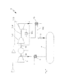
- FIG. 1 shows a first embodiment of the invention.
- the illustrated Power plant based on a conventional gas turbine group 1, comprising a compressor 101, a combustion chamber 102 and a turbine 103 for driving a generator 2. Furthermore, a compressor is 3rd arranged, which is driven by an electric motor 7. Compressor 101 and gas turbine 103 and generator 2 are useful by a common wave or connected to a common wave train 104th arranged.
- the compressor 3 is preferably lower in times Electricity demand and thus low electricity prices operated and promoted then a storage gas, preferably air, in a storage volume 4. Maritime can be interposed with advantage a cooler 5, so that the temperature in the Storage volume 4 does not increase too much as a result of compression.
- the Pressure ratio of the compressor 3 is greater than that of the gas turbine group 1, if the pressure in the storage volume 4 is greater than the maximum Compressor pressure of the gas turbine group must be.
- the compressor 3 with one or more here Equip not shown intermediate cooling stages, so that the heat each discharged at the lowest possible temperature. Between the Compressor 3 and the storage volume 4 is of course also a not shown check member necessary. If the price of electricity and / or the electricity demand a certain lower threshold exceeds or if the pressure in the memory 4 is an upper limit exceeds, the compressor 3 is taken out of service. In the storage room 4 is now stored "cheap" energy in the form of strained air.
- shut-off and throttle member 6 If the paid electricity price and / or demand a certain upper Limit exceeds a shut-off and throttle member 6 is opened, and Compressed gas or compressed air from the memory 4 is connected via a Connecting line 100, in which the shut-off and throttle member 6 is arranged is downstream of the compressor 101 in the flow path of the gas turbine group. 1 initiated. This additional gas mass flow is in the combustion chamber 102nd heated and working in the turbine 103, without dissipation in the compressor 101, resulting in an increase in net output leads.
- a standard gas turbine to relax the Storage gas can be used, in the example shown, the entire Wave train 104 including generator 2. If necessary, a generator with a larger marginal power can be used. Also, the Compressor 101 in a relatively simple manner and with little effort to one be scaled slightly smaller nominal mass flow, causing the Rated power of the gas turbine group 1 decreases, or the turbine 103 can for a higher swallowing ability are upscaled, which, however, in contrast to Compressor modification may require housing modifications. In In each case, the performance enhancement potential grows, and the gas turbine group is better suited for a peak load operation according to the invention. Likewise, the storage volume can be much smaller than one pure gas or air storage turbine.
- the compressor 3 can also can be purchased as standard and can be from the compressor 101 of the Gasturbo group have significantly different specifications; he will especially for smaller volume flows and higher pressure conditions selected. Even with a complete failure of the storage device, including Compressor 3 and storage volume 4, the power plant can still operated fully and only loses the ability to Peak load generation, but can continue to operate in nominal operation fully.
- the power plant according to the invention thus offers outstanding flexibility and operational and investment security for the operator.
- the generator 2 is also connected to a device via which the generator 2 for starting the gas turbine group is operable as a motor, or it is another start auxiliary device for starting the Gas turbo group 1 available.
- the Gas turbine group 1 are approached by the turbine 103 with compressed gas is acted upon from the memory 4.
- the gas turbine group 1 with the help of the compressed gas also de-energized or at most with a small dimensioning Emergency power supply, for example in the form of batteries, are approached.
- the embodiment according to FIG. 2 enables further here Flexibility.
- the compressor 3 is on the one hand with the electric drive motor. 7 connected, on the other hand, an external engine, such as a Diesel engine 8, via a coupling 9 on the shaft train of the compressor. 3 connectable.
- the power of the motor 8 can be made comparatively small become.
- a black start is now possible even with empty memory 4; It only needs to be started the engine 8, which successively the Compressor 3 drives and fills the accumulator 4 until the pressure to start enough.
- the charging compressor 3 on a shaft train with the Gas turbine group 1 and the generator 2 and arranged by means of a Coupling 10 can be coupled to this.
- transmission gear be present so that the speed of the Compressor 3 is above the grid synchronous speed of the generator 2.
- the clutch 10 closed; the generator 2 then supplies less power to the grid than the Gas turbine group net power output 1.
- the gas turbo group 1 is driving then the generator 2 and the charging compressor 3 at.
- the memory 4 is charged.
- the excess Performance of the gas turbine group 1 directly for driving the Loading compressors 3 are used, resulting in an extreme advantage of Power plant according to the invention over a conventional Power plant and a conventional gas storage power plant leads.
- the compressor is alternatively again via an external Motor 8 drivable.
- the generator 2 can be both regenerative and operated by an electric motor.
- the gas turbine group 1 can via a Clutch 11 completely separated from the generator 2.
- the clutch 11 is open and the Clutch 10 produces a positive connection.
- the compressor 3 can therefore also then operated when the gas turbine group 1 is stopped.
- the operating flexibility is increased, however, the shaft strand is up to the generator 2 no more standard.
- the gas turbo group 1 is still Standard, which offers great investment security.
- an external motor in particular an internal combustion engine, for driving the compressor 3 on the be arranged above described type.
- the additional firing is replaced by an exhaust gas heat exchanger 13. Since the exhaust gas mass flow is greater than the additional gas mass flow, it is in itself possible, without dew point in the exhaust gas, the additional gas until close to the temperature of the exhaust gases of the gas turbine to bring. at assumed 450 ° C compressor end temperature and 550 ° C Turbine outlet temperature, the additional gas can easily up to the Be warmed up compressor end temperature.
- the embodiments shown so far are characterized by particular low investment costs.
- the disadvantage is that the exhaust heat only is used incompletely.
- a preferred peak load operation is that with semi-closed lead series and nominal conditions unchanged turbine mass flow; At mass flow increase rise Exhaust losses relatively strong.
- the embodiments according to the The following FIGS. 8 to 12 have devices for using the Exhaust heat on, and can therefore with advantage also with maximum Turbine mass flow, according to the criteria defined above, namely the Limits of the firing capacity of the combustion chamber, if necessary simultaneous compliance with emission limits, as well as the tear - off limit of the Operational compressor, be operated economically.
- the embodiment according to FIG. 8 comprises, in addition to a gas turbine group 1 a gas storage power plant comprising two charging compressors 31, 32, which can be driven by motors 71, 72, and so in the top described manner, a storage volume 4 with compressed air charge, and a gas storage turbine or air turbine 14, which with the Gas turbine group 1 is arranged on a common shaft strand 104 and acts on a common generator 2.
- the gas storage turbine 14 is by a coupling 10 from the shaft train 104 decoupled to a Avoid ventilating in an uninvolved state; it is with Advantage of an automatic clutch, which releases the connection as soon as the Speed of the gas storage or air turbine 14 of the remaining Shaft line 104 falls below, and vice versa makes a connection, when the air turbine 14 at speed of the shaft train 104 a power can raise.
- Such couplings 10 belong to single-shaft Combined units (gas turbine with steam turbine) to the prior art and are the expert therefore readily familiar.
- a first part of the stored Gas via the actuator 6 of the gas turbine group 1 downstream of the compressor 101 are fed while another part on the shut-off and Actuator 15 can be directed into the gas storage and air turbine 14.
- Total mass flow of the gas or the air from the memory 4 can thereby be regulated by the mass flow of the gas storage turbine 14, that the entire waste heat potential is used.
- the mass flow of Turbine 103 can be increased up to the maximum discussed above since the waste heat potential is usable; an increase in the exhaust gas mass flow also leads to an increase in the gas storage turbine 14 degradable Heat potential and thus to a further increase in the total net output.
- CAES Compressed Air Energy Storage System
- the basic idea of a conventional CAES system is excess Energy derived from permanently operated conventional power plants such as e.g. Coal-fired power plants or nuclear power plants, during the low-load periods with low electricity price is generated to store. This is achieved by that with the help of cheap excess energy air or another Gas is pumped into a store under a relatively high pressure. Out this is the air or the corresponding storage gas when needed for Generation of electricity at peak loads, ie at a high electricity price again taken. That means the energy is in the form of potential energy is stored on demand. For example, used as storage Coal or salt mines or appropriately sized Pipe storage systems. Since the gas stored in the gas storage usually Air is, such a gas storage power plant is generally also as Air storage power plant called.
- FIG. 9 is a variation and optimization of the circuit of FIG entire gas mass flow discharged from the reservoir 4 flows through it first, the exhaust gas heat exchanger 13 and is on the gas storage turbine 14 at least partially processed before one of the shut-off and Actuator 6 dimensioned partially relaxed partial flow taken and the Gas turbine group is supplied.
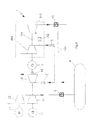
- Figures 10 and 11 show the realization of an inventive Power plant as combined plant with one of the gas turbine group 1 downstream water-steam cycle for waste heat recovery.
- the structure the gas turbine group 1 with gas storage 4 corresponds to the above illustrated embodiments.
- a steam turbine 21 is arranged.
- the water-steam cycle is exemplified greatly simplified and is the Skilled in the art, which is why only a very global Representation takes place.
- a preheater 22 and an evaporator / superheater 23 arranged in the exhaust gas stream of gas turbine group 1 arranged.
- a condensate pump 24 pumps or delivers water at a pressure of for example 2 to 5 bar to preheater 22, where the condensate is close to the boiling point is heated.
- This condensate is placed in a feedwater tank and Degasser 25 promoted.
- a boiler feed pump 26 applies this water Main steam pressure and promotes the feed water by the so-called OTSG "Once Through Steam Generator” running Steam generator / superheater 23.
- a steam control valve 27 controls the Fresh steam supply to the steam turbine 21.
- In the steam turbine 21 is the Steam relaxed and then condensed again in the cooler 28.
- the Cooler for the funded by the compressor 3 gas is in one Coolant circuit integrated with the cooler / condenser 28. That for cooling the gas supplied to the accumulator 4 and that of the steam turbine 21 discharged steam, a common radiator 28 is provided.
- the embodiment according to FIG. 11 is distinguished from FIG Embodiment according to Figure 10 by the furnace 12 for the additional gas out.
- the furnace 12 for the additional gas out instead of supplementary gas firing or in addition thereto, e.g. when Preheater, of course, can also be a device for the use of Exhaust heat to be arranged.
- the preheating of the additional gas is with Advantage, as in the other examples shown with Additional gas preheating, so regulated that the temperature of the additional gas of Temperature of the compressor tail gas corresponds.
- an operation with increased Turbine mass flow can be used particularly efficiently, because an increased Turbine and thus exhaust gas mass flow for increased steam production and thus for an additional power increase of the steam turbine 21 is usable.
- the Additional gas introduced downstream of the combustion chamber 102 of the gas turbine group 1 become. It is then necessary in the flow path of the additional gas Firing to arrange which the additional gas directly on the Turbine inlet temperature is able to heat.
- Such a construction is indeed to realize more complex, but can be of great advantage, if the Operation with increased turbine mass flow is sought. It has to be then no consideration for the limited firing capacity of the combustion chamber 102 the gas turbine group 1 are taken, which is advantageous to a Standard machine belongs and in particular with simultaneous observance of Emission limits only a limited firing capacity is able to implement.
- the compressed gas in particular the compressed air
- the pressure gas storage 4 to increase the rated power of the gas turbine 103rd and / or used to start the gas turbine 103.
- the compressed gas in particular the compressed air
- the compressor 3 which serves to charge the compressed gas reservoir 4
- the shaft train 104 of the gas turbine group 1 can be coupled.
- the excess gas turbine group 1 power can be used for Driving the compressor 3, so for charging the gas pressure accumulator. 4 be used.
- the generator 2 as an electric motor operated to stand at the stationary gas turbine group 1, the compressor.
Priority Applications (2)
| Application Number | Priority Date | Filing Date | Title |
|---|---|---|---|
| EP03104359A EP1536118A1 (fr) | 2003-11-25 | 2003-11-25 | Centrale électrique |
| DE102004034657A DE102004034657A1 (de) | 2003-07-16 | 2004-07-16 | Kraftwerksanlage |
Applications Claiming Priority (1)
| Application Number | Priority Date | Filing Date | Title |
|---|---|---|---|
| EP03104359A EP1536118A1 (fr) | 2003-11-25 | 2003-11-25 | Centrale électrique |
Publications (1)
| Publication Number | Publication Date |
|---|---|
| EP1536118A1 true EP1536118A1 (fr) | 2005-06-01 |
Family
ID=34443053
Family Applications (1)
| Application Number | Title | Priority Date | Filing Date |
|---|---|---|---|
| EP03104359A Withdrawn EP1536118A1 (fr) | 2003-07-16 | 2003-11-25 | Centrale électrique |
Country Status (1)
| Country | Link |
|---|---|
| EP (1) | EP1536118A1 (fr) |
Cited By (2)
| Publication number | Priority date | Publication date | Assignee | Title |
|---|---|---|---|---|
| CN103758642A (zh) * | 2014-01-23 | 2014-04-30 | 中国科学院工程热物理研究所 | 一种压缩页岩气储能发电系统 |
| CN111441867A (zh) * | 2020-03-20 | 2020-07-24 | 中国科学院工程热物理研究所 | 一种用于燃气轮机联合循环发电机组的压缩空气储能系统 |
Citations (6)
| Publication number | Priority date | Publication date | Assignee | Title |
|---|---|---|---|---|
| US3988897A (en) * | 1974-09-16 | 1976-11-02 | Sulzer Brothers, Limited | Apparatus for storing and re-utilizing electrical energy produced in an electric power-supply network |
| WO1994005904A1 (fr) * | 1992-08-28 | 1994-03-17 | Abb Carbon Ab | Installation de turbine a gaz avec compresseur additionnel |
| US5379589A (en) * | 1991-06-17 | 1995-01-10 | Electric Power Research Institute, Inc. | Power plant utilizing compressed air energy storage and saturation |
| US5934063A (en) * | 1998-07-07 | 1999-08-10 | Nakhamkin; Michael | Method of operating a combustion turbine power plant having compressed air storage |
| DE10236324A1 (de) * | 2001-08-17 | 2003-03-06 | Alstom Switzerland Ltd | Verfahren zum Kühlen von Turbinenschaufeln |
| US20030131599A1 (en) * | 2002-01-11 | 2003-07-17 | Ralf Gerdes | Power generation plant with compressed air energy system |
-
2003
- 2003-11-25 EP EP03104359A patent/EP1536118A1/fr not_active Withdrawn
Patent Citations (6)
| Publication number | Priority date | Publication date | Assignee | Title |
|---|---|---|---|---|
| US3988897A (en) * | 1974-09-16 | 1976-11-02 | Sulzer Brothers, Limited | Apparatus for storing and re-utilizing electrical energy produced in an electric power-supply network |
| US5379589A (en) * | 1991-06-17 | 1995-01-10 | Electric Power Research Institute, Inc. | Power plant utilizing compressed air energy storage and saturation |
| WO1994005904A1 (fr) * | 1992-08-28 | 1994-03-17 | Abb Carbon Ab | Installation de turbine a gaz avec compresseur additionnel |
| US5934063A (en) * | 1998-07-07 | 1999-08-10 | Nakhamkin; Michael | Method of operating a combustion turbine power plant having compressed air storage |
| DE10236324A1 (de) * | 2001-08-17 | 2003-03-06 | Alstom Switzerland Ltd | Verfahren zum Kühlen von Turbinenschaufeln |
| US20030131599A1 (en) * | 2002-01-11 | 2003-07-17 | Ralf Gerdes | Power generation plant with compressed air energy system |
Cited By (3)
| Publication number | Priority date | Publication date | Assignee | Title |
|---|---|---|---|---|
| CN103758642A (zh) * | 2014-01-23 | 2014-04-30 | 中国科学院工程热物理研究所 | 一种压缩页岩气储能发电系统 |
| CN103758642B (zh) * | 2014-01-23 | 2015-10-07 | 中国科学院工程热物理研究所 | 一种压缩页岩气储能发电系统 |
| CN111441867A (zh) * | 2020-03-20 | 2020-07-24 | 中国科学院工程热物理研究所 | 一种用于燃气轮机联合循环发电机组的压缩空气储能系统 |
Similar Documents
| Publication | Publication Date | Title |
|---|---|---|
| EP1917428B1 (fr) | Procédé d'operation d'une centrale electrique equipee d'un reservoir sous pression | |
| DE112004001587B4 (de) | Kraftwerksanlage und Verfahren zum Betrieb | |
| EP0439754B1 (fr) | Méthode de démarrage d'une centrale combinée | |
| EP2122129B1 (fr) | Centrale électrique et procédé de fonctionnement | |
| EP0563553B1 (fr) | Refroidissement de turbines par air | |
| EP1795725B1 (fr) | Turbine à gaz avec réglage de l'air de refroidissement | |
| DE102004007482B4 (de) | Kraftwerksanlage | |
| DE112009000663B4 (de) | Verfahren zum betrieb einer kraftwerksanlage | |
| EP2574739A1 (fr) | Installation de stockage d'énergie thermique et son procédé de fonctionnement | |
| WO2012163667A1 (fr) | Centrale adiabatique d'accumulation à air comprimé | |
| DE4410440A1 (de) | Druckluftenergiespeicherverfahren und -system | |
| DE4213023A1 (de) | Verfahren zum Betrieb eines Gasturbogruppe | |
| WO2011036136A1 (fr) | Centrale électrique comportant une vanne de régulation de surcharge | |
| EP2614236A1 (fr) | Centrale électrique | |
| WO2005121510A1 (fr) | Procede pour exploiter une centrale electrique et centrale electrique | |
| DE10236326A1 (de) | Gasspeicherkraftanlage | |
| DE19902437B4 (de) | Verfahren und Vorrichtung zum schnellen Anfahren und zur schnellen Leistungssteigerung einer Gasturbinenanlage | |
| DE2437782C3 (de) | Verfahren zum Anfahren einer Gasturbinen-Anlage zur Stromerzeugung aus Brenngas von einem Kohle-Druckvergaser | |
| DE2822575C2 (de) | Verfahren zum Anfahren einer Luftspeicher-Gasturbinenanlage | |
| EP1790834A1 (fr) | Turbogénérateur avec dispositif de démarrage | |
| DE102004034657A1 (de) | Kraftwerksanlage | |
| DE102004040890A1 (de) | Kraftwerksanlage, und Verfahren zum Betrieb | |
| EP0530519A1 (fr) | Centrale électrique chauffée par l'énergie nucléaire et fossile | |
| DE2102770A1 (de) | Anlage einer Gasturbine mit Energiespeicherung gebunden mit einer Dampfturbine | |
| EP1536118A1 (fr) | Centrale électrique |
Legal Events
| Date | Code | Title | Description |
|---|---|---|---|
| PUAI | Public reference made under article 153(3) epc to a published international application that has entered the european phase |
Free format text: ORIGINAL CODE: 0009012 |
|
| AK | Designated contracting states |
Kind code of ref document: A1 Designated state(s): AT BE BG CH CY CZ DE DK EE ES FI FR GB GR HU IE IT LI LU MC NL PT RO SE SI SK TR |
|
| AX | Request for extension of the european patent |
Extension state: AL LT LV MK |
|
| AKX | Designation fees paid | ||
| STAA | Information on the status of an ep patent application or granted ep patent |
Free format text: STATUS: THE APPLICATION IS DEEMED TO BE WITHDRAWN |
|
| 18D | Application deemed to be withdrawn |
Effective date: 20051202 |
|
| REG | Reference to a national code |
Ref country code: DE Ref legal event code: 8566 |