EP1536073A2 - Reduced water consumption flush toilet having a common actuation mechanism that controls a water valve by a first flexible cable and controls a waste valve by asecond flexible cable - Google Patents
Reduced water consumption flush toilet having a common actuation mechanism that controls a water valve by a first flexible cable and controls a waste valve by asecond flexible cable Download PDFInfo
- Publication number
- EP1536073A2 EP1536073A2 EP04027617A EP04027617A EP1536073A2 EP 1536073 A2 EP1536073 A2 EP 1536073A2 EP 04027617 A EP04027617 A EP 04027617A EP 04027617 A EP04027617 A EP 04027617A EP 1536073 A2 EP1536073 A2 EP 1536073A2
- Authority
- EP
- European Patent Office
- Prior art keywords
- cam
- lever
- valve
- toilet
- bowl
- Prior art date
- Legal status (The legal status is an assumption and is not a legal conclusion. Google has not performed a legal analysis and makes no representation as to the accuracy of the status listed.)
- Withdrawn
Links
Images


Classifications
-
- E—FIXED CONSTRUCTIONS
- E03—WATER SUPPLY; SEWERAGE
- E03D—WATER-CLOSETS OR URINALS WITH FLUSHING DEVICES; FLUSHING VALVES THEREFOR
- E03D11/00—Other component parts of water-closets, e.g. noise-reducing means in the flushing system, flushing pipes mounted in the bowl, seals for the bowl outlet, devices preventing overflow of the bowl contents; devices forming a water seal in the bowl after flushing, devices eliminating obstructions in the bowl outlet or preventing backflow of water and excrements from the waterpipe
- E03D11/02—Water-closet bowls ; Bowls with a double odour seal optionally with provisions for a good siphonic action; siphons as part of the bowl
- E03D11/10—Bowls with closure elements provided between bottom or outlet and the outlet pipe; Bowls with pivotally supported inserts
-
- E—FIXED CONSTRUCTIONS
- E03—WATER SUPPLY; SEWERAGE
- E03D—WATER-CLOSETS OR URINALS WITH FLUSHING DEVICES; FLUSHING VALVES THEREFOR
- E03D5/00—Special constructions of flushing devices, e.g. closed flushing system
- E03D5/02—Special constructions of flushing devices, e.g. closed flushing system operated mechanically or hydraulically (or pneumatically) also details such as push buttons, levers and pull-card therefor
- E03D5/08—Special constructions of flushing devices, e.g. closed flushing system operated mechanically or hydraulically (or pneumatically) also details such as push buttons, levers and pull-card therefor directly by the foot combined with devices for opening or closing shutters in the bowl outlet and/or with devices for raising or lowering seat and cover and/or for swiveling the bowl
Definitions
- the present invention relates to waste management systems. More particularly, the present invention relates to a flush toilet. More specifically, but without restriction to the particular embodiment and/or use which is shown and described for purposes of illustration, the present invention pertains to a reduced water consumption flush toilet.
- Vehicles including recreational vehicles (“RVs”), airplanes, boats, trains, and the like often include toilets for the comfort and convenience of the passengers.
- the toilets of vehicles must perform under operating conditions that are significantly different from non-transitory toilets conventionally found in homes and businesses (“home toilets”).
- home toilets For example, vehicle toilets are typically required to operate often in a confined area and often rely on a source of on-board water for flushing. For the latter reason, vehicle toilets are typically designed to operate with reduced water consumption for water conservation.
- United States Patent No. 5,060,320 discloses a toilet having a foot pedal flush control arrangement including two pedals. One of the pedals opens a toilet bowl discharge outlet and the other pedal supplies flush water to the bowl. The pedals both operate through actuation cables having a wire member slidable within a conduit.
- the flush water pedal can be independently actuated to partially fill the bowl prior to use of the toilet while the outlet closure member pedal co-acts with the flush water pedal so that upon opening of the bowl outlet, the flush water pedal is depressed providing water to the bowl.
- the wire members are solid wire members coupled to the pedals for both pull and push operation so that upon a failure of the pedal return mechanism, the pedals can be manually returned closing the bowl outlet and terminating the flow of flush water to the bowl.
- the present invention provides a reduced water consumption flush toilet including a bowl assembly defining a bowl and a discharge opening at a lower end of the bowl.
- the toilet additionally includes a valve mounted to the flush toilet for selectively opening and closing the discharge opening of the bowl assembly and a water valve for selectively delivering a source of flush water to the bowl.
- the toilet further includes a common actuator assembly for controlling both the waste valve and the water valve. The actuator assembly is coupled to the water valve through a first flexible cable and coupled to the waste valve through a second flexible cable.
- the actuator assembly include a lever that is movable from a first position to an intermediate position and from the intermediate position to a second position such that in the first position the waste valve closes the discharge opening and the water valve assembly is in the closed condition, in the intermediate position the waste valve closes the discharge opening and the water valve is in the open position for adding water to the bowl, and in the second position the waste valve opens the discharge opening and the water valve is in the open position for flushing the bowl.
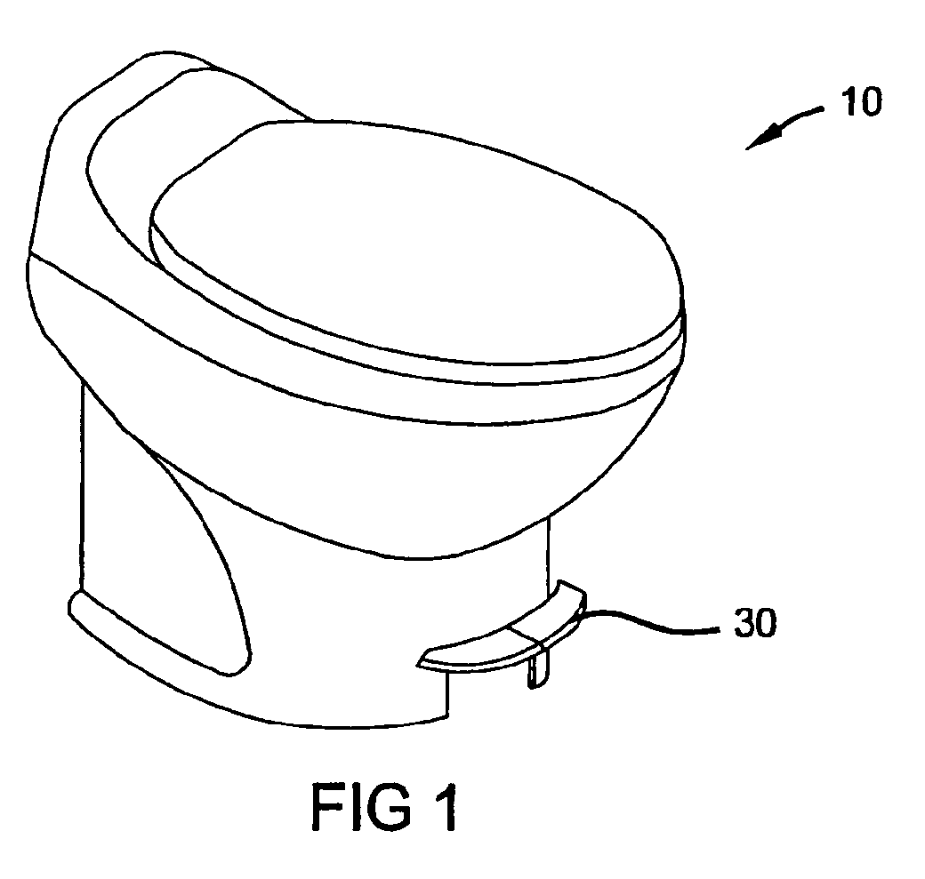
- Figure 1 is a front perspective view of a reduced water consumption toilet constructed in accordance with the teachings of a preferred embodiment of the present invention.
- Figure 2 is a schematic illustration showing the interconnection of the actuator with the water valve and waste valve.
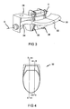
- FIG 3 is an enlarged perspective view of the actuator assembly of the reduced water consumption toilet of Figure 1.
- Figure 4 is a top view of the reduced water consumption toilet of Figure 1.
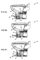
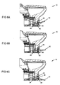
- Figures 5A-5C represent a series of cross-sectional views taken along the line 5-5 of Figure 4 through a first cam and first cam follower of the actuator as the actuator rotates from a closed position (Figure 5A), to a water-add position (Figure 5B), and to a flush position (Figure 5C).
- Figures 6A-6C represent a series of cross-sectional views taken along the line 6-6 of Figure 4 through a second cam and second cam follower of the actuator as the actuator rotates from a closed position (Figure 6A), to a water-add position (Figure 6B), and to a flush position ( Figure 6C).
- Figure 7 is an enlarged portion of the cross-sectional view of Figure 5A.
- Figure 8 is an enlarged cross-sectional view of Figure 6A.
- a reduced water consumption flush toilet constructed according to the teachings of a preferred embodiment of the present invention is illustrated and generally identified at reference character 10.
- the flush toilet 10 is intended to be operated with a reduced amount of water.
- Such reduced water consumption flush toilets are particularly desirable for motor vehicle such as a recreational vehicle or the like where the water supply is limited.
- the reduced water consumption flush toilet 10 of the present invention is illustrated to generally include a water valve 12 and a waste valve 14.
- the water valve 12 is operative for delivering a source of water from a source of water 16 to a bowl 18 of the toilet 10 for flushing of the bowl 18.
- the waste valve 16 is selectively operable for opening a discharge outlet 20 defined by a lower portion of the bowl 18.
- the water valve 12 and the waste valve 14 are conventional in construction. Suitable water valves and waste valves are well known in the art and available from Thetford Corporation of Ann Arbor, Michigan, for example.
- the water valve 14 is opened by a first flexible cable 22.
- the waste valve 16 is similarly controlled for selective opening of the discharge outlet 20 by a second flexible cable 24.
- the actuator assembly 26 is foot actuated.
- the actuator assembly 26 is illustrated in the drawings to generally include a mounting portion 28 and a foot lever 30. The mounting portion 28 is secured to a base of the toilet 10.
- the foot lever 30 is illustrated to generally include a central portion 32 that extends from the base of the toilet 10 and a pair of mounting arms 34.
- Figure 3 illustrates one of the arms 34. It will be understood that the other arm is a mirror image thereof.
- the arms 34 pivotally coupled to the mounting portion 28 for rotation about a common pivot axis X.
- pivotally attachment of the arms 34 permits the lever 30 to articulate from a first position (as shown in Figures 5A and 6A) to a second position (as shown in Figures 5C and 6C) downwardly pivoted about 25° from the first position.
- articulation of the lever 30 from the first position to an intermediate position functions to add water to the bowl 18 without opening the discharge opening 20.
- the actuator assembly is further illustrated to include a first cam member 36 and a second cam member 38.
- the first and second cam members 36 and 38 are rotatably mounted to the mounting portion 28.
- the first and second cam members 36 and 38 are mounted to the mounting portion 28 for articulation about a common pivot axis Y.
- the common pivot axis Y is positioned upwardly and forwardly relative to the pivot axis X.
- Upper ends of the first and second cam members 36 and 38 are pivotally coupled to the mounting portion 28.
- the first and second flexible cables 22 and 24 are secured to lower ends of the first and second cam members 36 and 38.
- a rear surface 40 of the first cam member 36 defines a cam following surface for cooperating with a cam 44 carried by the lever 30.
- the cam 44 is shown to include a convexly curved surface 45 for engaging the cam following surface 40.
- the cam following surface 40 includes a central raised portion 47.
- a rear surface 46 of the second cam member 38 similarly defines a cam following surface for cooperating with a cam 48 carried by the lever 30.
- the cam 48 is again shown to include a convexly curved surface 49 for engaging the cam following surface 46.
- the cam following surface 46 includes a central recessed portion 51.
Landscapes
- Engineering & Computer Science (AREA)
- Health & Medical Sciences (AREA)
- Life Sciences & Earth Sciences (AREA)
- Hydrology & Water Resources (AREA)
- Public Health (AREA)
- Water Supply & Treatment (AREA)
- Mechanical Engineering (AREA)
- Aviation & Aerospace Engineering (AREA)
- Sanitary Device For Flush Toilet (AREA)
Abstract
Description
- The present invention relates to waste management systems. More particularly, the present invention relates to a flush toilet. More specifically, but without restriction to the particular embodiment and/or use which is shown and described for purposes of illustration, the present invention pertains to a reduced water consumption flush toilet.
- Vehicles including recreational vehicles ("RVs"), airplanes, boats, trains, and the like often include toilets for the comfort and convenience of the passengers. The toilets of vehicles must perform under operating conditions that are significantly different from non-transitory toilets conventionally found in homes and businesses ("home toilets"). For example, vehicle toilets are typically required to operate often in a confined area and often rely on a source of on-board water for flushing. For the latter reason, vehicle toilets are typically designed to operate with reduced water consumption for water conservation.
- The design of vehicle toilets must accommodate the distinct operating conditions and preferably provide the customer with the comforts and customary features associated with home toilets. One example of a vehicle toilet is shown and described in commonly assigned United States Patent No. 5,060,320 which is hereby incorporated by reference as if fully set forth herein. United States Patent No. 5,060,320 discloses a toilet having a foot pedal flush control arrangement including two pedals. One of the pedals opens a toilet bowl discharge outlet and the other pedal supplies flush water to the bowl. The pedals both operate through actuation cables having a wire member slidable within a conduit. The flush water pedal can be independently actuated to partially fill the bowl prior to use of the toilet while the outlet closure member pedal co-acts with the flush water pedal so that upon opening of the bowl outlet, the flush water pedal is depressed providing water to the bowl. The wire members are solid wire members coupled to the pedals for both pull and push operation so that upon a failure of the pedal return mechanism, the pedals can be manually returned closing the bowl outlet and terminating the flow of flush water to the bowl.
- While known vehicle toilets, including the toilet disclosed by United States Patent No. 5,060,320, have proven acceptable for their intended applications, there remains a need for continuous improvement in the pertinent art.
- It is an object of the present invention to provide a reduced water consumption flush toilet for a motor vehicle that has a common actuation mechanism that controls a water valve by a first flexible cable and controls a waste valve by a second flexible cable.
- It is a more particular object of the present invention to provide a reduced water consumption flush toilet for a motor vehicle that includes a common actuator coupled to a water valve through a first flexible cable and coupled to a waste valve through a second flexible cable such that such movement of the actuator from a first position to an intermediate position opens the water valve without opening the waste valve for adding flush water to the bowl and movement of the actuator from the intermediate position to a second position opens the waste valve and opens the water valve for flushing of the toilet.
- It is a related object of the present invention to provide reduced water consumption flush toilet having a common actuator coupled to a water valve though a first flexible cable and coupled to a waste valve through a second flexible cable the actuator including a first and second cam member members having distinct following surfaces for cooperating with the first and second flexible cables, respectively.
- In one form, the present invention provides a reduced water consumption flush toilet including a bowl assembly defining a bowl and a discharge opening at a lower end of the bowl. The toilet additionally includes a valve mounted to the flush toilet for selectively opening and closing the discharge opening of the bowl assembly and a water valve for selectively delivering a source of flush water to the bowl. The toilet further includes a common actuator assembly for controlling both the waste valve and the water valve. The actuator assembly is coupled to the water valve through a first flexible cable and coupled to the waste valve through a second flexible cable. The actuator assembly include a lever that is movable from a first position to an intermediate position and from the intermediate position to a second position such that in the first position the waste valve closes the discharge opening and the water valve assembly is in the closed condition, in the intermediate position the waste valve closes the discharge opening and the water valve is in the open position for adding water to the bowl, and in the second position the waste valve opens the discharge opening and the water valve is in the open position for flushing the bowl.
- The present invention will become more fully understood from the detailed description and the accompanying drawings, wherein:
- Figure 1 is a front perspective view of a reduced water consumption toilet constructed in accordance with the teachings of a preferred embodiment of the present invention.
- Figure 2 is a schematic illustration showing the interconnection of the actuator with the water valve and waste valve.
- Figure 3 is an enlarged perspective view of the actuator assembly of the reduced water consumption toilet of Figure 1.
- Figure 4 is a top view of the reduced water consumption toilet of Figure 1.
- Figures 5A-5C represent a series of cross-sectional views taken along the line 5-5 of Figure 4 through a first cam and first cam follower of the actuator as the actuator rotates from a closed position (Figure 5A), to a water-add position (Figure 5B), and to a flush position (Figure 5C).
- Figures 6A-6C represent a series of cross-sectional views taken along the line 6-6 of Figure 4 through a second cam and second cam follower of the actuator as the actuator rotates from a closed position (Figure 6A), to a water-add position (Figure 6B), and to a flush position (Figure 6C).
- Figure 7 is an enlarged portion of the cross-sectional view of Figure 5A.
- Figure 8 is an enlarged cross-sectional view of Figure 6A.
- The following description of the preferred apparatus of the present invention is merely exemplary in nature and is in no way intended to limit the invention, its application, or uses.
- With reference to Figures 1 through 6A-6C of the drawings, a reduced water consumption flush toilet constructed according to the teachings of a preferred embodiment of the present invention is illustrated and generally identified at
reference character 10. In the particular embodiment illustrated, theflush toilet 10 is intended to be operated with a reduced amount of water. Such reduced water consumption flush toilets are particularly desirable for motor vehicle such as a recreational vehicle or the like where the water supply is limited. After a reading of the remainder of this detailed description, however, those skilled in the art will readily appreciate that certain teachings of the present invention are not limited to reduced water consumption toilets. Rather, various of the teachings of the present invention have applicability to other vehicle and non-vehicle applications. - As schematically shown in Figure 2, the reduced water consumption
flush toilet 10 of the present invention is illustrated to generally include a water valve 12 and awaste valve 14. The water valve 12 is operative for delivering a source of water from a source ofwater 16 to abowl 18 of thetoilet 10 for flushing of thebowl 18. Thewaste valve 16 is selectively operable for opening adischarge outlet 20 defined by a lower portion of thebowl 18. Insofar as the present invention is concerned, the water valve 12 and thewaste valve 14 are conventional in construction. Suitable water valves and waste valves are well known in the art and available from Thetford Corporation of Ann Arbor, Michigan, for example. - In a manner to be more fully discussed below, the
water valve 14 is opened by a firstflexible cable 22. Thewaste valve 16 is similarly controlled for selective opening of thedischarge outlet 20 by a secondflexible cable 24. - Operation of the
water valve 14 and thewaste valve 16 is controlled by anactuator assembly 26. In the embodiment illustrated, theactuator assembly 26 is foot actuated. Theactuator assembly 26 is illustrated in the drawings to generally include a mountingportion 28 and afoot lever 30. The mountingportion 28 is secured to a base of thetoilet 10. - The
foot lever 30 is illustrated to generally include acentral portion 32 that extends from the base of thetoilet 10 and a pair of mountingarms 34. Figure 3 illustrates one of thearms 34. It will be understood that the other arm is a mirror image thereof. Thearms 34 pivotally coupled to the mountingportion 28 for rotation about a common pivot axis X. Explaining further, pivotally attachment of thearms 34 permits thelever 30 to articulate from a first position (as shown in Figures 5A and 6A) to a second position (as shown in Figures 5C and 6C) downwardly pivoted about 25° from the first position. As will be further discussed below, articulation of thelever 30 from the first position to an intermediate position functions to add water to thebowl 18 without opening thedischarge opening 20. Continued articulation of thelever 30 from the intermediate position to the second position functions to selectively open thedischarge outlet 20 of the bowl assembly 12 and functions to selectively deliver a source of flush water to thebowl 18 for flushing. It will be appreciated by those skilled in that art that various teachings of the present invention may alternatively be employed with a hand actuated lever or an electronically controlled arrangement. - The actuator assembly is further illustrated to include a
first cam member 36 and asecond cam member 38. The first andsecond cam members portion 28. In the embodiment illustrated, the first andsecond cam members mounting portion 28 for articulation about a common pivot axis Y. The common pivot axis Y is positioned upwardly and forwardly relative to the pivot axis X. Upper ends of the first andsecond cam members portion 28. The first and secondflexible cables second cam members - A
rear surface 40 of thefirst cam member 36 defines a cam following surface for cooperating with acam 44 carried by thelever 30. Thecam 44 is shown to include a convexlycurved surface 45 for engaging thecam following surface 40. Thecam following surface 40 includes a central raisedportion 47. - A
rear surface 46 of thesecond cam member 38 similarly defines a cam following surface for cooperating with acam 48 carried by thelever 30. Thecam 48 is again shown to include a convexlycurved surface 49 for engaging thecam following surface 46. Thecam following surface 46 includes a central recessedportion 51. - With particular reference to the cross-sectional views of Figures 5A through 5C and 7, operation of the
actuator assembly 26 to control the water valve 12 will be further described. When thelever 30 is in the first position, thecam 44 carried by thelever 30 engages an upper portion of thecam following surface 40 of thefirst cam member 36. When thelever 30 is downwardly articulated to the intermediate position, thecam 44 carried by thelever 30 rides on the raisedportion 47 of thecam following surface 40 and forces thefirst cam member 36 to rotate clockwise (as shown in Figure 7, for example). Clockwise rotation of thefirst cam member 36 operates to pull the firstflexible cable 22 secured to the lower end of thefirst cam member 36 for actuating the water valve 12. In this manner, water is added to thebowl 18 of thetoilet 10. As will be addressed below, thewaste valve 14 remains closed. - As the
lever 30 is articulated from the intermediate position to the second position, thecam 40 rides down off the raisedportion 47 of thecam following surface 40. In this manner, the relative rotation of thefirst cam member 36 about the pivot axis Y is relatively maintained as thelever 30 is further rotated downwardly. As will be discussed below, in this lever position thewaste valve 14 is now open for flushing of thebowl 18. - With particular reference to the cross-sectional views of Figures 6A through 6C and 8, operation of the
actuator assembly 26 to control thewaste valve 14 will be further described. When thelever 30 is in the first position, thecam 44 carried by thelever 30 engages an upper portion of thecam following surface 46 of thesecond cam member 38. When thelever 30 is downwardly articulated to the intermediate position, thecam 48 carried by thelever 30 is received within the recessedportion 49 of thecam following surface 46 and prevents significant rotation of thesecond cam member 38 about the pivot axis Y. In this manner, the secondflexible cable 24 secured to the lower end of thesecond cam member 38 is not pulled and thewaste valve 14 remains closed for the adding of water to thebowl 18 prior to flushing. - As the
lever 30 is articulated from the intermediate position to the second position, thecam 44 rides past the recessed portion of thecam following surface 46. In this manner, thesecond cam member 38 is forced to rotate counterclockwise about the pivot axis Y (as shown in Figure 8, for example). This clockwise rotation of thesecond cam member 38 about the pivot axis Y functions to pull the secondflexible cable 24 for opening of thewaste valve 14 as water continues to flow into thebowl 18 from the water valve 12. - The description of the invention is merely exemplary in nature and, thus, variations that do not depart from the gist of the invention are intended to be within the scope of the invention. Such variations are not to be regarded as a departure from the spirit and scope of the invention.
Claims (14)
- A reduced water consumption flush toilet for a motor vehicle comprising:a bowl assembly defining a bowl and a discharge opening at a lower end of the bowl;a base downwardly extending from the bowl assembly;a waste valve mounted to the flush toilet for selectively opening and closing the discharge opening of the bowl assembly;a water valve for selectively delivering a source of flush water to the bowl; anda common actuator assembly mounted to the base for controlling both the waste valve and the water valve, the actuator assembly coupled to the water valve through a first flexible cable and coupled to the waste valve through a second flexible cable, the actuator assembly including a lever movable from a first position to an intermediate position and from the intermediate position to a second position such that in the first position the waste valve closes the discharge opening and the water valve is in the closed condition, in the intermediate position the waste valve closes the discharge opening and the water valve is in the open position for adding water to the bowl, and in the second position the waste valve opens the discharge opening and the water valve is in the open position for flushing the bowl.
- The reduced water consumption flush toilet of Claim 1, wherein the actuator assembly includes a first cam member and a second cam member, the first and second cam members having distinct following surfaces for cooperating with one or more cam members carried by the lever.
- The reduced water consumption flush toilet of Claim 1, wherein the lever is a foot controlled lever.
- The reduced water consumption flush toilet of Claim 1, wherein the first and second flexible cables are secured to the first and second cam members.
- The reduced water consumption flush toilet of Claim 2, wherein the first and second cam members are both mounted to the toilet for pivotal motion.
- The reduced water consumption flush toilet of Claim 2, wherein the first and second cam members are mounted to the toilet for pivotal motion about a common pivot axis.
- The reduced water consumption flush toilet of Claim 1, wherein the lever is rotatably mounted to the toilet.
- The reduced water consumption flush toilet of Claim 7, wherein the actuator assembly includes a mounting portion and the lever is rotatably mounted to the mounting portion.
- The reduced water consumption flush toilet of Claim 8, wherein the bowl assembly and the base are constructed of china and the mounting portion is constructed of plastic.
- The reduced water consumption flush toilet of Claim 2, wherein the first cam member is pivotally coupled to the toilet for rotation about a first pivot axis and includes a first cam following surface for engaging a first cam member carried by the lever, the first cam following surface configured such that the first cam follower causes the first cam member to pivot about the first pivot axis as the lever is moved from the first position to the intermediate position.
- The reduced water consumption flush toilet of Claim 2, wherein the second cam member is pivotally coupled to the toilet for rotation about a second pivot axis and includes a second cam following surface for engaging a second cam member carried by the lever, the second cam following surface configured such that the second cam follower avoids substantial rotation about the first pivot axis as the lever is moved from the first position to the second position and causes the second cam member to pivot about the second pivot axis as the lever is moved from the intermediate position to the second position.
- The reduced water consumption flush toilet of Claim 2, wherein the first cam member is pivotally coupled to the toilet for rotation about a first pivot axis and includes a first cam following surface for engaging a first cam member carried by the lever, the first cam following surface configured such that the first cam follower causes the first cam member to pivot about the first pivot axis as the lever is moved from the first position to the intermediate position; and
further wherein the second cam member is pivotally coupled to the toilet for rotation about a second pivot axis and includes a second cam following surface for engaging a second cam member carried by the lever, the second cam following surface configured such that the second cam follower avoids substantial rotation about the first pivot axis as the lever is moved from the first position to the second position and causes the second cam member to pivot about the second pivot axis as the lever is moved from the intermediate position to the second position. - The reduced water consumption flush toilet of Claim 10, wherein the first cam following surface includes a raised central portion.
- The reduced water consumption flush toilet of Claim 11, wherein the second cam following surface includes a recessed portion.
Applications Claiming Priority (2)
| Application Number | Priority Date | Filing Date | Title |
|---|---|---|---|
| US723287 | 1991-06-28 | ||
| US72328703A | 2003-11-26 | 2003-11-26 |
Publications (2)
| Publication Number | Publication Date |
|---|---|
| EP1536073A2 true EP1536073A2 (en) | 2005-06-01 |
| EP1536073A3 EP1536073A3 (en) | 2007-05-16 |
Family
ID=34465704
Family Applications (1)
| Application Number | Title | Priority Date | Filing Date |
|---|---|---|---|
| EP04027617A Withdrawn EP1536073A3 (en) | 2003-11-26 | 2004-11-20 | Reduced water consumption flush toilet having a common actuation mechanism that controls a water valve by a first flexible cable and controls a waste valve by asecond flexible cable |
Country Status (1)
| Country | Link |
|---|---|
| EP (1) | EP1536073A3 (en) |
Cited By (1)
| Publication number | Priority date | Publication date | Assignee | Title |
|---|---|---|---|---|
| CN107401202A (en) * | 2017-08-30 | 2017-11-28 | 朱昌霞 | A convenient squatting toilet |
Citations (1)
| Publication number | Priority date | Publication date | Assignee | Title |
|---|---|---|---|---|
| US5060320A (en) | 1990-06-25 | 1991-10-29 | Thetford Corporation | Recreational vehicle toilet with foot pedal flush |
Family Cites Families (3)
| Publication number | Priority date | Publication date | Assignee | Title |
|---|---|---|---|---|
| US4710988A (en) * | 1986-02-19 | 1987-12-08 | Sanitation Equipment Limited | Flush toilet |
| US5875499A (en) * | 1998-01-23 | 1999-03-02 | Thetford Corporation | Recreational vehicle toilet with flush nozzle deflector shield |
| US5933882A (en) * | 1998-06-05 | 1999-08-10 | Sanitation Equipment Limited | Lever-actuated flush toilet |
-
2004
- 2004-11-20 EP EP04027617A patent/EP1536073A3/en not_active Withdrawn
Patent Citations (1)
| Publication number | Priority date | Publication date | Assignee | Title |
|---|---|---|---|---|
| US5060320A (en) | 1990-06-25 | 1991-10-29 | Thetford Corporation | Recreational vehicle toilet with foot pedal flush |
Cited By (1)
| Publication number | Priority date | Publication date | Assignee | Title |
|---|---|---|---|---|
| CN107401202A (en) * | 2017-08-30 | 2017-11-28 | 朱昌霞 | A convenient squatting toilet |
Also Published As
| Publication number | Publication date |
|---|---|
| EP1536073A3 (en) | 2007-05-16 |
Similar Documents
| Publication | Publication Date | Title |
|---|---|---|
| US8176577B2 (en) | Flush toilet with improved flow pattern | |
| US5548850A (en) | Toilet with two flush modalities | |
| US4710988A (en) | Flush toilet | |
| US8459731B2 (en) | Head restraint and seat stow flat handle | |
| US20060208520A1 (en) | Seat assembly with automatic stow feature | |
| EP2060684A1 (en) | Toilet with controller controlling water inlet vavle and flush valve | |
| AU6246794A (en) | Dual flush mechanism | |
| EP1536073A2 (en) | Reduced water consumption flush toilet having a common actuation mechanism that controls a water valve by a first flexible cable and controls a waste valve by asecond flexible cable | |
| WO2005076963A3 (en) | Reversible seat assembly | |
| US6913121B2 (en) | Auxiliary system for an automobile parked on a slope | |
| EP1946983B1 (en) | Device and method for automatically actuating a parking brake handle of a vehicle | |
| US4403524A (en) | Headlamp door lever assembly | |
| AU2004202296A1 (en) | Toilet flushing arrangement | |
| EP1645692A1 (en) | Electro-mechanical flush mechanism | |
| EP1445151A1 (en) | An electromechanically controlled retractable step for a vehicle | |
| CA3196498C (en) | Watercraft drain plug system | |
| US20110167550A1 (en) | Water-Saving Toilets and Methods of Using the Same | |
| US5933882A (en) | Lever-actuated flush toilet | |
| EP1191158A3 (en) | Device for controlling the discharge valve of a lavatory flush tank | |
| US20070176434A1 (en) | Motor vehicle lock | |
| JP3719412B2 (en) | Armrest device | |
| US20250207440A1 (en) | Double pull inside door handle mechanism with electrical and mechanical actuation | |
| AU2020308523B2 (en) | Sliding cover assembly for a vehicle, in particular for a water-borne vehicle | |
| US966407A (en) | Water-closet valve. | |
| AU733105B2 (en) | Vehicle door control system |
Legal Events
| Date | Code | Title | Description |
|---|---|---|---|
| PUAI | Public reference made under article 153(3) epc to a published international application that has entered the european phase |
Free format text: ORIGINAL CODE: 0009012 |
|
| AK | Designated contracting states |
Kind code of ref document: A2 Designated state(s): AT BE BG CH CY CZ DE DK EE ES FI FR GB GR HU IE IS IT LI LU MC NL PL PT RO SE SI SK TR |
|
| AX | Request for extension of the european patent |
Extension state: AL HR LT LV MK YU |
|
| PUAL | Search report despatched |
Free format text: ORIGINAL CODE: 0009013 |
|
| AK | Designated contracting states |
Kind code of ref document: A3 Designated state(s): AT BE BG CH CY CZ DE DK EE ES FI FR GB GR HU IE IS IT LI LU MC NL PL PT RO SE SI SK TR |
|
| AX | Request for extension of the european patent |
Extension state: AL HR LT LV MK YU |
|
| AKX | Designation fees paid | ||
| STAA | Information on the status of an ep patent application or granted ep patent |
Free format text: STATUS: THE APPLICATION IS DEEMED TO BE WITHDRAWN |
|
| 18D | Application deemed to be withdrawn |
Effective date: 20071117 |
|
| REG | Reference to a national code |
Ref country code: DE Ref legal event code: 8566 |