EP1536048A1 - Picking device of weaving machine - Google Patents
Picking device of weaving machine Download PDFInfo
- Publication number
- EP1536048A1 EP1536048A1 EP03791191A EP03791191A EP1536048A1 EP 1536048 A1 EP1536048 A1 EP 1536048A1 EP 03791191 A EP03791191 A EP 03791191A EP 03791191 A EP03791191 A EP 03791191A EP 1536048 A1 EP1536048 A1 EP 1536048A1
- Authority
- EP
- European Patent Office
- Prior art keywords
- sub
- electromagnetic switching
- switching valve
- nozzle
- fluid
- Prior art date
- Legal status (The legal status is an assumption and is not a legal conclusion. Google has not performed a legal analysis and makes no representation as to the accuracy of the status listed.)
- Withdrawn
Links
Images


Classifications
-
- D—TEXTILES; PAPER
- D03—WEAVING
- D03D—WOVEN FABRICS; METHODS OF WEAVING; LOOMS
- D03D47/00—Looms in which bulk supply of weft does not pass through shed, e.g. shuttleless looms, gripper shuttle looms, dummy shuttle looms
- D03D47/28—Looms in which bulk supply of weft does not pass through shed, e.g. shuttleless looms, gripper shuttle looms, dummy shuttle looms wherein the weft itself is projected into the shed
- D03D47/30—Looms in which bulk supply of weft does not pass through shed, e.g. shuttleless looms, gripper shuttle looms, dummy shuttle looms wherein the weft itself is projected into the shed by gas jet
- D03D47/3026—Air supply systems
- D03D47/306—Construction or details of parts, e.g. valves, ducts
-
- D—TEXTILES; PAPER
- D03—WEAVING
- D03D—WOVEN FABRICS; METHODS OF WEAVING; LOOMS
- D03D47/00—Looms in which bulk supply of weft does not pass through shed, e.g. shuttleless looms, gripper shuttle looms, dummy shuttle looms
- D03D47/28—Looms in which bulk supply of weft does not pass through shed, e.g. shuttleless looms, gripper shuttle looms, dummy shuttle looms wherein the weft itself is projected into the shed
- D03D47/30—Looms in which bulk supply of weft does not pass through shed, e.g. shuttleless looms, gripper shuttle looms, dummy shuttle looms wherein the weft itself is projected into the shed by gas jet
-
- D—TEXTILES; PAPER
- D03—WEAVING
- D03D—WOVEN FABRICS; METHODS OF WEAVING; LOOMS
- D03D47/00—Looms in which bulk supply of weft does not pass through shed, e.g. shuttleless looms, gripper shuttle looms, dummy shuttle looms
- D03D47/28—Looms in which bulk supply of weft does not pass through shed, e.g. shuttleless looms, gripper shuttle looms, dummy shuttle looms wherein the weft itself is projected into the shed
- D03D47/30—Looms in which bulk supply of weft does not pass through shed, e.g. shuttleless looms, gripper shuttle looms, dummy shuttle looms wherein the weft itself is projected into the shed by gas jet
- D03D47/3006—Construction of the nozzles
- D03D47/302—Auxiliary nozzles
Definitions
- the present invention relates to a picking device of a loom, the device comprising one or more sub-nozzle units in which sub-nozzles and electromagnetic switching valves are connected through pipes in one-to-one relationship.
- a picking device of a loom comprises one or more sub-nozzle units in which sub-nozzles and electromagnetic switching valves are communicated through pipes in one-to-one relationship, and a fluid supply source for supplying a compressed fluid to the electromagnetic switching valves.
- the above-mentioned conventional arts can reduce the consumption of the compressed fluid by controlling the time and the timing for jetting the fluid from each sub-nozzle. In recent energy-saving ages, however, further reduction in consumption of the compressed fluid is desired.
- An object of the present invention is to realize further reduction in consumption of a compressed fluid of a picking device in a loom.
- the inventors of the present application found that the consumption of the compressed fluid can be relatively easily reduced by setting an effective sectional area and a content volume of a fluid channel of each sub-nozzle unit within a predetermined range when the weft is inserted into warp shed, and invented the following technique.
- Any one of the picking devices relative to the present invention comprises at least one sub-nozzle unit in which sub-nozzle and electromagnetic switching valve are connected through a pipe in one-to-one relationship.
- a first picking device relative to the present invention further comprises a fluid supply source for supplying the compressed fluid to the electromagnetic switching valve of the sub-nozzle unit, wherein the effective sectional area of the fluid channel from a fluid outlet of the fluid supply source to an input end portion on the sub-nozzle side of the pipe is between 2.5 mm 2 and 3.5 mm 2 , both inclusive.
- the effective sectional area of the fluid channel from the input port of the electromagnetic switching valve to the output port of the electromagnetic switching valve is between 5 mm 2 and 15 mm 2 , both inclusive.
- the content volume of the fluid channel from the valve body side end portion of the valve seat opening of the electromagnetic switching valve to the input end of the sub-nozzle is between 2000 mm 3 and 3000 mm 3 , both inclusive.
- the "content volume” herein means the volume of the inside of the fluid channel in the above-mentioned section.
- the content volume of the fluid channel inside the electromagnetic switching valve from the valve body side end portion of the valve seat opening of the electromagnetic switching valve to the output port of the electromagnetic switching valve is 600 mm 3 or less.
- a fifth picking device relative to the present invention further comprises a fluid supply source for supplying the compressed fluid to the electromagnetic switching valve of the sub-nozzle device, wherein the effective sectional area of the fluid channel from the fluid outlet of the fluid supply source to the sub-nozzle side input end portion of the pipe is between 2.5 mm 2 and 3.5 mm 2 , both inclusive, and the content volume of the fluid channel from the valve body-side end portion of the valve seat opening of the electromagnetic switching valve to the input end of the sub-nozzle is between 2000 mm 3 and 3000 mm 3 , both inclusive.
- the effective sectional area of the fluid channel from the input port of the electromagnetic switching valve to the output port of the electromagnetic switching valve is between 5 mm 2 and 15 mm 2 , both inclusive, and the content volume of the fluid channel inside the electromagnetic switching valve from the valve body side end portion of the valve seat opening of the electromagnetic switching valve to the output port of the electromagnetic switching valve is 600 mm 3 or less.
- the consumption of the compressed fluid is reduced while the pressure and the jetting time of the compressed fluid jetted from the sub-nozzle are kept at proper values so that the weft may arrive at the non-weft insert side.
- the minimum jetting period corresponding to weft running can be set, and the resistance of the compressed fluid in the fluid channel can be controlled, so that the consumption of the compressed fluid is further reduced.
- the minimum jetting period corresponding to the weft running can be set, so that the residual pressure exhaustion (in other words, wasteful blowing) after the jetting of the compressed fluid jetted from the sub-nozzle is reduced, thereby saving the consumption of the compressed fluid.
- the picking device 10 of a loom is used for an air jet loom which uses the compressed air, for example, as a fluid for weft insertion.
- the weft 14 wound around a weft package 12 is measured to be divided into a predetermined length by the length measurement and storage unit 16, engaged with the engagement pin device 18, and stored in the length measurement and storage unit 16 with the front end portion led into the main nozzle 20.
- the weft 14 led into the main nozzle 20 is released for a certain period by an engagement pin device 18, jetted from the main nozzle 20 together with the compressed air and inserted into the shed of the warp 24 by the compressed air jetted from a plurality of sub-nozzles 22.
- a release sensor 32 counts the number of times that the released weft 14 crossed a sensor region of the release sensor 32, and when it reached a predetermined number of times, engages the weft 14 again by the engagement pin device 18 and stores the weft 14 of a predetermined length by the length measurement and storage unit 16.
- a portion of the inserted weft 14 is beaten by the reed 26 against the cloth fell of the cloth 28, cut off by the cutter 30 and cut away from the weft portion connected to the length measurement and storage unit 16 through the main nozzle 20.
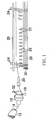
- the picking device 10 to be used in an air jet loom comprises a plurality of sub-nozzle units 34 and a fluid supply source 36 for supplying the compressed air to the sub-nozzle units 34.
- Each sub-nozzle unit 34 has the sub-nozzles 22 and electromagnetic switching valves 38 connected in one-to-one relationship through a sub-nozzle side pipe 40 and receives the compressed air from the fluid supply source 36 at the electromagnetic switching valve 38.
- the fluid supply source 36 means one that supplies the compressed air to the electromagnetic switching valve 38; in other words, one that is in the upstream of the electromagnetic switching valve 38.
- the fluid supply source 36 is indicated by reference numeral 36, and for example, a tank 42 such as an air tank corresponds to it.
- the compressed air is supplied from a pressure source 44 such as a compressor to the tank 42 through a pressure regulator 46.
- the tank 42 as the fluid supply source 36 has the same number of fluid outlets 48 from which the compressed air flows out as the number of the electromagnetic switching valves 38.
- the fluid outlet 48 of the fluid supply source 36 is formed by a tank side pipe 50 attached to the tank 42.
- the tank side pipe 50 is communicated to the electromagnetic switching valve 38 air-tightly through an input-side connector (inlet-said connector) 54 inserted into the input port 52 of the electromagnetic switching valve 38.
- tank side pipe 50 may be dispensed with, in which case the electromagnetic switching valve 38 is attached directly to the tank 42.
- An output-side connector (outlet-said connector) 58 for making the inside compressed air flow out to the sub-nozzle side pipe 40 is inserted into the output port 56 of the electromagnetic switching valve 38.
- the electromagnetic switching valve 38 generally includes an electromagnetic switching valve case 60, an annular exciting coil 62, an iron core 64 to be moved up and down by excitation or non-excitation of the exciting coil 62, a valve body 66 assembled into the lower end of the iron core 64, a compression spring 68 for applying the downward force to the valve body 66, and a valve seat 70 opposing the valve body 66.
- the input port 52 and the output port 56 are communicated through a valve seat opening 72 formed inside the electromagnetic switching valve case 60.
- the compression spring 68 is disposed so that the valve body 66 comes into contact with the valve body-side end portion of the valve seat opening 72 to block the valve seat opening 72 when the exciting current is not supplied to the exciting coil 62 (when the exciting current is OFF).
- the exciting coil 62 has a doughnut-like shape which enables to accommodate the upper end portion of the iron core 64. This exciting coil 62 is excited when the exciting current is supplied (when the exciting current is ON). By this, since the iron core 64 pulled upward, the compression spring 68 is compressed, and the valve body 66 is pulled up toward the exciting coil 62, resulting in opening the valve seat opening 72.
- the exciting coil 62 is turned into a non-exciting state when the exciting current is not supplied.
- the valve body 66 is moved toward the valve seat 70 and pressed against the valve seat 70 to block the valve seat opening 72 at its valve body-side end portion, by an accompanying force of the compression spring 68.
- the sub-nozzle 22 is provided at its front end with a jet hole 22a for jetting the compressed air.
- the sub-nozzle 22 is communicated to the electromagnetic switching valve 38 through the sub-nozzle side pipe 40.
- the compressed air from the output port 56 of the electromagnetic switching valve 38 is supplied to the input end 22b of the sub-nozzle 22 through the sub-nozzle side pipe 40.
- a sub-nozzle side connector 74 is air-tightly connected to the sub-nozzle side pipe 40, and air-tightly attached to the input end 22b of the sub-nozzle 22.
- a sub-nozzle support 76 is firmly assembled into a lead holder (not shown) which moves integrally with the reed 26 by a suitable fixture such as a bolt in a state of assembling the sub-nozzle 22.
- the first fluid channel K1 is a fluid channel from the fluid outlet 48 of the fluid supply source 36 to the input end 22b which is the end portion on the side of the sub-nozzle 22 of the sub-nozzle side pipe 40.
- the second fluid channel K2 is a fluid channel from the input port 52 of the electromagnetic switching valve 38 to the output port 56 of the electromagnetic switching valve 38, and more particularly, a fluid channel excepting a portion into which the input side connector 54 and the output side connector 58 are inserted.
- the third fluid channel K3 is a fluid channel from the valve body side end portion of the valve seat opening 72 of the electromagnetic switching valve 38 to the input end 22b of the sub-nozzle 22.
- the fourth fluid channel K4 is a fluid channel from the valve body side end portion of the valve seat opening 72 of the electromagnetic switching valve 38 to the output port 56 of the electromagnetic switching valve 38 (excepting a portion into which the output side connector 58 is inserted).
- the diameter of the jet hole 22a of the sub-nozzle 22 was set at1.5 mm in all the embodiments.
- the conditions for the experiment and the method of measurement were as follows.
- a plurality of picking devices 10 provided with various first fluid channels K1 different in effective sectional areas were produced.
- the value of the pressure of the compressed air of a pressure regulator 46 was made constant (0.5 MPa) throughout this experiment 1-1 and was not changed during the experiment.
- the respective flow rates of the compressed air were measured on the two kinds of the test devices for experiment by using a flow meter 78 provided between the pressure regulator 46 and the fluid supply source 36, and the average value of the flow rates of the compressed air obtained from these two test devices was adopted as the flow rate of the compressed air relative to the effective sectional area of the first fluid channel K1.
- a tank side pressure sensor 80 was provided for measuring the inner pressure of the fluid supply source 36.
- the "effective sectional area” herein is a synonym of "effective sectional area of a valve” in the JIS (Japanese Industrial Standards) terms for air pressure and hydraulics. According to its definition, it means “a sectional area in calculation by converting a pressure resistance into an equivalent orifice, based on an actual flow rate of a valve and used as an indication value of capability of the flow of an air pressure valve.”
- the effective sectional area of the first fluid channel K1 is the indication value representing the capability of the flow when the compressed air is discharged from the jet hole 22a of the sub-nozzle 22 of the sub-nozzle unit 34 communicated to the fluid supply source 36 in a state of choking flow, and a sectional area of an ideal contraction without any friction or contraction.
- the measurement result of the flow rate of the compressed air is shown in Fig. 3 by a line 101.
- the greater the effective sectional area of the first fluid channel K1 the more the flow rate of the compressed air.
- the supply pressure of the compressed air being the same in both cases, the greater the effective sectional area of the first fluid channel becomes, the more easily the compressed air flows.
- test device As the pressure values of the compressed air from the test device and the pressure regulator 46, the test device and the values used in experiment 1-1 were used, respectively.
- a tank side pressure sensor 80 was provided for measuring the internal pressure of the fluid supply source 36, and a nozzle side sensor 82 was provided in the neighborhood of the sub-nozzle side end portion of the sub-nozzle side pipe 40.
- a pressure difference obtained by subtracting the value of the measured pressure of the nozzle side pressure sensor 82 from the value of the measured pressure of the tank side pressure sensor 80 was used, and the average value of the pressure differences obtained from two kinds of the test devices for experiment pressure was adopted as the pressure loss with respect to the effective sectional area of the first fluid channel K1.
- test device 10 In order to measure the consumption of the pressure fluid of the picking device 10, a test device having the effective sectional area of the first fluid channel K1 used in the foregoing experiment 1-1 was prepared for each sub-nozzle, and each test device was attached to a loom to weave actually.
- the pressure of the compressed air from the pressure regulator 46 was set at the optimum value which enables to obtain jetting proper for picking with respect to two test devices having the same effective sectional area of the first fluid channel K1.
- the set values of the loom were: the kind of the weft 14, polyester 84dtex; the cloth width, 170 cm; and the rotation frequency of main shaft of the loom, 800 rpm.
- the measurement result of the air consumption is shown in Fig. 3 by a line 103.
- the effective sectional area of the first fluid channel K1 is 3.5 mm 2
- the consumption of the compressed air becomes the minimum
- the consumption of the compressed air increases or decreases from the value, the consumption of the compressed air increased.
- the reason why the consumption of the compressed air increases when the effective sectional area of the first fluid channel K1 exceeds 3.5 mm 2 is considered to be that the content volumes of the electromagnetic switching valve 38 and the sub-nozzle side pipe 40 increase, thereby increasing the residual pressure exhaustion amount at the end of jetting of the compressed air of the sub-nozzle 22 ends.
- the effective sectional area of the first fluid channel K1 exceeds 3.5 mm 2 , the electromagnetic switching valve 38 becomes larger and causes such problems as a space restriction for disposing the electromagnetic switching valve 38, and the electromagnetic switching valve 38 is costly; therefore, the effective sectional area of the first fluid channel K1 is preferably 3.5 mm 2 or less.
- the effective sectional area of the first fluid channel K1 is determined according to the sectional area of each component of the first fluid channel K1. Consequently, the inner diameter and length of the sub-nozzle side pipe 40 are restricted by a quality (material) of the sub-nozzle side pipe 40, the location of the first fluid channel K1, etc. Furthermore, the inner diameter and length of the sub-nozzle side pipe 40 influence the pressure loss of the first fluid channel K1, the effective sectional area of the first fluid channel K1 depends on the inner diameter and length of the sub-nozzle side pipe 40. A result of study in terms of designing revealed that the lowest value of the effective sectional area of the first fluid channel K1 was 2.5 mm 2 .
- the preferable effective sectional area of the first fluid channel K1 from the fluid outlet 48 of the fluid supply source 36 to the input end 22b of the sub-nozzle 22 of the sub-nozzle side pipe 40 is between 2.5 mm 2 and 3.5 mm 2 , both inclusive.
- the range (the X-axis in Fig. 3) of the effective sectional area of the first fluid channel K1 obtained by the experiments 1-1, 1-2 and 1-3 is converted, by using Formula (1), into the effective sectional area of the second fluid channel K2 from the input port 52 of the electromagnetic switching valve 38 to the output port 56 of the electromagnetic switching valve 38.
- Formula (1) can be changed to Formula (2).
- S 2 1 S 2 1 + 1 S 2 2 + ⁇ + 1 S 2 n + 1 S 2 x
- S shows the total effective sectional area of the picking device 10
- S 1 , S 2 , ..., S n shows the effective sectional areas of the sub-nozzle side pipes 40 and connectors 54, 58, 74
- S x shows the effective sectional area of the electromagnetic switching valve 38, respectively.
- the effective sectional area S x of the electromagnetic switching valve 38 does not include the effective sectional area of a portion where the connectors 54 and 58 are to be inserted.
- Fig. 4 The result of the calculation of Formula (2) is shown in Fig. 4.
- the line 104 shows the pressure loss
- the line 105 shows the flow rate of the compressed air, respectively. From Fig. 4, it is understood that a range with a great flow rate of the compressed air and a small pressure loss of the compressed area is where the effective area S x of the electromagnetic switching valve 38 is between 5 mm 2 and 15 mm 2 , both inclusive.
- a plurality of picking devices 10 provided with various third fluid channels K3 having different content volumes were produced to measure the flow rate and pressure loss of the compressed air of the picking devices 10.
- the picking devices 10 relative to respective content volumes of the third fluid channels K3, two kinds of them were prepared in which the lengths and inner diameters of the sub-nozzle side pipes 40 or the electromagnetic switching valves 38 were changed.
- the set value of the supply pressure of the pressure regulator 46 was made a constant value (0.5 MPa) throughout the present experiment 3-1 and not changed halfway.
- the time for exhausting the residual pressure was computed, using a memory which stores signals of the electromagnetic switching valve 38 and signals of nozzle side pressure sensor 82, from their measured values.
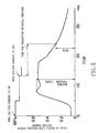
- the time for exhausting the residual pressure was defined as a time from when a closing output (stopping electricity to an exciting coil 62, i.e., turning off the exciting current) is commanded to the electromagnetic switching valve 38 till when the value of the nozzle side pressure sensor 82 is lowered to 50% of the maximum pressure before the command for the closing output (See Fig. 5).
- the time for exhausting the residual pressure of test devices of which the third fluid channels K3 have the same content volume is measured respectively, the averaged value of the times for exhausting the residual pressure of the test devices of which the content volumes of the third fluid channels K3 are the same was defined as the time for exhausting the residual pressure relative to the content volume.
- the reason for this is considered: the greater the content volume of the third fluid channel K3 becomes, the exhaustion amount of the compressed air remaining within the fluid channel increases. Consequently, the smaller the content volumes of the third fluid channel K3, the smaller the consumption of the compressed air.
- the residual pressure jetting amount (the residual pressure exhaust amount after the compressed air jetting ended), which the compressed air remaining within the fluid channel K3 jets from the sub-nozzle 22, decreases.
- test devices having the content volumes of the third fluid channels K3 in the above-mentioned experiment 3-1 were produced and attached to looms, and actual weaving was carried out.
- the pressure of the compressed air from the pressure regulator 46 was set at an optimum value at which suitable jetting for weft insertion can be obtained from the sub-nozzle 22 relative to two test devices of which the content volumes from the third fluid channels K3 are the same.
- the kind of the weft selected was polyester 84dtex
- the width of the cloth was 337 cm
- the rotation frequency of the main shaft of the loom was 750 rpm.
- the consumption of the compressed air of all the sub-nozzles during operation of the looms was measured, similarly to the experiment 1-3.
- the total of the measured consumption was made the consumption of the compressed air.
- the consumption of the compressed air was 65.8 Nm 3 /H when the content volume of the third fluid channel K3 was 3100 mm 3 and when the content volume of the fourth fluid channel K4 was 1000 mm 3 .
- the consumption of the compressed air was 59.5 Nm 3 /H when the content volume of the third fluid channel K3 was 2500 mm 3 and when the content volume of the fourth fluid channel K4 was 520 mm 3 , in the present invention.
- the content volume is preferably 3000 mm 3 or less.
- the inner diameter of the sub-nozzle side pipe 40 should be small; however, due to such a problem as a limit in strength of the sub-nozzle side pipe 40 and a pressure loss of the sub-nozzle side pipe 40, there is a lower limit of the inner diameter of the sub-nozzle side pipe 40.
- the lower limit of the content volume of the third fluid channel K3 was set at 2000 mm 3 .
- the content volume of the third fluid channel K3 from the valve body side end of the valve seat opening 72 of the electromagnetic switching valve 38 to the input end 22b of the sub-nozzle 22 is preferably between 2000 mm 3 and 3000 mm 3 , both inclusive.
- the fourth fluid channel K4 from the valve seat opening 72 of the electromagnetic switching valve 38 to the output port 56 of the electromagnetic switching valve 38 is a part of the third fluid channel K3. So, by subtracting the content volumes of the sub-nozzle side pipe 40 and connectors 58, 74 from the content volume of the third fluid channel K3, the content volume from the valve body-side end of the valve seat opening 72 of the electromagnetic switching valve 38 to the output port 56 can be obtained. That is to say, by using Formula (3), the range of the content volume (X-axis in Fig. 6) of the third fluid channel K3 obtained by experiments 3-1 and 3-2 is converted into the content volume of the fourth fluid channel K4 from the valve body side end of the valve seat opening 72 of the electromagnetic switching valve 38 to the output port 56 of the electromagnetic switching valve 38.
- V x V -( V 1 + V 2 + ⁇ + V n )
- V shows the content volume of the third fluid channel K3 from the valve body side end of the valve seat opening 72 of the electromagnetic switching valve 38 to the input end 22b of the sub-nozzle 22
- V 1 , V 2 , ..., V n show the content volumes of the sub-nozzle side pipe 40 and the connectors 58, 74
- V x shows the content volume from the valve body side end of the valve seat opening 72 of the electromagnetic switching valve 38 to the output port 56.
- the content volume V x of the electromagnetic valve 38 does not include the content volume of a portion where the output side connector 58 is to be inserted.
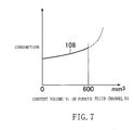
- Fig. 7 the consumption of the compressed air relative to the content volume provided by Formula (3) from the valve body side end of the valve seat opening 72 of the electromagnetic switching valve 38 to the output port 56 of the electromagnetic switching valve 38 is shown by a line 108.
- the proper range of the content volume V x of the fourth fluid channel K4 is considered to be 600 mm 3 or less.
- the consumption of the compressed air is reduced also by constituting a picking device and an electromagnetic switching valve which satisfy both the effective sectional area of the first fluid channel K1 and the content volume of the third fluid channel K3 as obtained in the above.
- the consumption of the compressed air is reduced also by constituting a picking device and an electromagnetic switching valve which satisfy both the effective sectional area of the second fluid channel K2 and the content volume of the fourth fluid channel K4 as obtained in the above.
- the consumption of the compressed air is reduced also by constituting a picking device and an electromagnetic switching valve which satisfy both the effective sectional areas of the first and second fluid channels K1, K2 and the content volumes of the third and fourth fluid channels K3, K4 as obtained in the above.
- the foregoing picking devices can be applied to, besides the compressed air, compressed fluid having a similar property to the compressed air, as a result of which the consumption of the compressed fluid is reduced.
Landscapes
- Engineering & Computer Science (AREA)
- Textile Engineering (AREA)
- Looms (AREA)
Abstract
The present invention aims at further reduction of the consumption
of a compressed fluid in a picking device (10) of a loom. The picking device
(10) of the loom comprises at least one of sub-nozzle units (34) in which a
sub-nozzle (22) and an electromagnetic switching valve (38) are connected
in one-to-one relationship through a pipe (40) so that a compressed air can
flow, and is characterized by defining the effective sectional area of a fluid
channel (K1) from a fluid outlet (48) of a fluid supply source (36) to the
input end (22b) of the sub-nozzle (22) of the pipe (40), the effective sectional
area of a fluid channel (K2) from an input port (52) of the electromagnetic
switching valve (38) to an output port (56) of the electromagnetic switching
valve (38), the content volume of the fluid channel (K3) from the valve body
side end of the valve seat opening (72) of the electromagnetic switching
valve (38) to the input end (22b) of the sub-nozzle (22), or the content
volume of the fluid channel (K4) from the valve body side end of the valve
seat opening (72) of the electromagnetic switching valve (38) to the output
port (56) of the electromagnetic switching valve (38) in a specific range.
Description
The present invention relates to a picking device of a loom, the device
comprising one or more sub-nozzle units in which sub-nozzles and
electromagnetic switching valves are connected through pipes in one-to-one
relationship.
As examples of conventional picking devices of looms, arts described
in the Official Gazettes of Japanese Patent Appln. Public Disclosures
(KOKAI) No. 10-204750 and No. 57-210043 are known.
According to them, a picking device of a loom comprises one or more
sub-nozzle units in which sub-nozzles and electromagnetic switching valves
are communicated through pipes in one-to-one relationship, and a fluid
supply source for supplying a compressed fluid to the electromagnetic
switching valves.
These conventional arts have the electromagnetic switching valve
corresponding to each sub-nozzle so as to be controlled individually and
attempt to save consumption of the compressed fluid by setting the time for
jetting the compressed fluid as well as the jet timing of the compressed
fluid individually.
The above-mentioned conventional arts can reduce the consumption
of the compressed fluid by controlling the time and the timing for jetting
the fluid from each sub-nozzle. In recent energy-saving ages, however,
further reduction in consumption of the compressed fluid is desired.
An object of the present invention is to realize further reduction in
consumption of a compressed fluid of a picking device in a loom.
The inventors of the present application found that the consumption
of the compressed fluid can be relatively easily reduced by setting an
effective sectional area and a content volume of a fluid channel of each
sub-nozzle unit within a predetermined range when the weft is inserted
into warp shed, and invented the following technique.
Any one of the picking devices relative to the present invention
comprises at least one sub-nozzle unit in which sub-nozzle and
electromagnetic switching valve are connected through a pipe in one-to-one
relationship.
A first picking device relative to the present invention further
comprises a fluid supply source for supplying the compressed fluid to the
electromagnetic switching valve of the sub-nozzle unit, wherein the
effective sectional area of the fluid channel from a fluid outlet of the fluid
supply source to an input end portion on the sub-nozzle side of the pipe is
between 2.5 mm2 and 3.5 mm2, both inclusive.
In a second picking device relative to the present invention, the
effective sectional area of the fluid channel from the input port of the
electromagnetic switching valve to the output port of the electromagnetic
switching valve is between 5 mm2 and 15 mm2, both inclusive.
In a third picking device relative to the present invention, the content
volume of the fluid channel from the valve body side end portion of the
valve seat opening of the electromagnetic switching valve to the input end
of the sub-nozzle is between 2000 mm3 and 3000 mm3, both inclusive. The
"content volume" herein means the volume of the inside of the fluid channel
in the above-mentioned section.
In a fourth picking device relative to the present invention, the
content volume of the fluid channel inside the electromagnetic switching
valve from the valve body side end portion of the valve seat opening of the
electromagnetic switching valve to the output port of the electromagnetic
switching valve is 600 mm3 or less.
A fifth picking device relative to the present invention further
comprises a fluid supply source for supplying the compressed fluid to the
electromagnetic switching valve of the sub-nozzle device, wherein the
effective sectional area of the fluid channel from the fluid outlet of the fluid
supply source to the sub-nozzle side input end portion of the pipe is
between 2.5 mm2 and 3.5 mm2, both inclusive, and the content volume of
the fluid channel from the valve body-side end portion of the valve seat
opening of the electromagnetic switching valve to the input end of the
sub-nozzle is between 2000 mm3 and 3000 mm3, both inclusive.
In a sixth picking device relative to the present invention, the
effective sectional area of the fluid channel from the input port of the
electromagnetic switching valve to the output port of the electromagnetic
switching valve is between 5 mm2 and 15 mm2, both inclusive, and the
content volume of the fluid channel inside the electromagnetic switching
valve from the valve body side end portion of the valve seat opening of the
electromagnetic switching valve to the output port of the electromagnetic
switching valve is 600 mm3 or less.
The result of the experiments conducted by the inventors has revealed
that the effective sectional area and the content volume of the fluid channel
in which the compressed fluid flows have a close relationship with the
consumption of the compressed fluid.
By setting the effective sectional areas or the content volumes of the
fluid channels in which the compressed fluid flows at the values of the first
through sixth picking devices, the consumption of the compressed fluid is
reduced while the pressure and the jetting time of the compressed fluid
jetted from the sub-nozzle are kept at proper values so that the weft may
arrive at the non-weft insert side.
In particular, by providing at least one sub-nozzle unit in which
sub-nozzle and electromagnetic switching valve are connected in one-to-one
relationship through a pipe, the minimum jetting period corresponding to
weft running can be set, and the resistance of the compressed fluid in the
fluid channel can be controlled, so that the consumption of the compressed
fluid is further reduced.
Also, according to the third through the sixth picking devices, since the
content volumes of the fluid channels are set at the third to the sixth
values mentioned above, the minimum jetting period corresponding to the
weft running can be set, so that the residual pressure exhaustion (in other
words, wasteful blowing) after the jetting of the compressed fluid jetted
from the sub-nozzle is reduced, thereby saving the consumption of the
compressed fluid.
Referring to Figs. 1 and 2, the picking device 10 of a loom is used for
an air jet loom which uses the compressed air, for example, as a fluid for
weft insertion.
As shown in Fig. 1, in the air jet loom, the weft 14 wound around a
weft package 12 is measured to be divided into a predetermined length by
the length measurement and storage unit 16, engaged with the
engagement pin device 18, and stored in the length measurement and
storage unit 16 with the front end portion led into the main nozzle 20.
The weft 14 led into the main nozzle 20 is released for a certain period
by an engagement pin device 18, jetted from the main nozzle 20 together
with the compressed air and inserted into the shed of the warp 24 by the
compressed air jetted from a plurality of sub-nozzles 22.
A release sensor 32 counts the number of times that the released weft
14 crossed a sensor region of the release sensor 32, and when it reached a
predetermined number of times, engages the weft 14 again by the
engagement pin device 18 and stores the weft 14 of a predetermined length
by the length measurement and storage unit 16.
A portion of the inserted weft 14 is beaten by the reed 26 against the
cloth fell of the cloth 28, cut off by the cutter 30 and cut away from the weft
portion connected to the length measurement and storage unit 16 through
the main nozzle 20.
As shown in Fig. 2, the picking device 10 to be used in an air jet loom
comprises a plurality of sub-nozzle units 34 and a fluid supply source 36 for
supplying the compressed air to the sub-nozzle units 34.
Each sub-nozzle unit 34 has the sub-nozzles 22 and electromagnetic
switching valves 38 connected in one-to-one relationship through a
sub-nozzle side pipe 40 and receives the compressed air from the fluid
supply source 36 at the electromagnetic switching valve 38.
The fluid supply source 36 means one that supplies the compressed
air to the electromagnetic switching valve 38; in other words, one that is in
the upstream of the electromagnetic switching valve 38. In this figure, the
fluid supply source 36 is indicated by reference numeral 36, and for
example, a tank 42 such as an air tank corresponds to it. The compressed
air is supplied from a pressure source 44 such as a compressor to the tank
42 through a pressure regulator 46. The tank 42 as the fluid supply
source 36 has the same number of fluid outlets 48 from which the
compressed air flows out as the number of the electromagnetic switching
valves 38.
The fluid outlet 48 of the fluid supply source 36 is formed by a tank
side pipe 50 attached to the tank 42. The tank side pipe 50 is
communicated to the electromagnetic switching valve 38 air-tightly
through an input-side connector (inlet-said connector) 54 inserted into the
input port 52 of the electromagnetic switching valve 38.
However, the tank side pipe 50 may be dispensed with, in which case
the electromagnetic switching valve 38 is attached directly to the tank 42.
An output-side connector (outlet-said connector) 58 for making the
inside compressed air flow out to the sub-nozzle side pipe 40 is inserted
into the output port 56 of the electromagnetic switching valve 38.
The electromagnetic switching valve 38 generally includes an
electromagnetic switching valve case 60, an annular exciting coil 62, an
iron core 64 to be moved up and down by excitation or non-excitation of the
exciting coil 62, a valve body 66 assembled into the lower end of the iron
core 64, a compression spring 68 for applying the downward force to the
valve body 66, and a valve seat 70 opposing the valve body 66.
The input port 52 and the output port 56 are communicated through a
valve seat opening 72 formed inside the electromagnetic switching valve
case 60. The compression spring 68 is disposed so that the valve body 66
comes into contact with the valve body-side end portion of the valve seat
opening 72 to block the valve seat opening 72 when the exciting current is
not supplied to the exciting coil 62 (when the exciting current is OFF).
The exciting coil 62 has a doughnut-like shape which enables to
accommodate the upper end portion of the iron core 64. This exciting coil
62 is excited when the exciting current is supplied (when the exciting
current is ON). By this, since the iron core 64 pulled upward, the
compression spring 68 is compressed, and the valve body 66 is pulled up
toward the exciting coil 62, resulting in opening the valve seat opening 72.
The exciting coil 62 is turned into a non-exciting state when the
exciting current is not supplied. By this, the valve body 66 is moved
toward the valve seat 70 and pressed against the valve seat 70 to block the
valve seat opening 72 at its valve body-side end portion, by an
accompanying force of the compression spring 68.
The sub-nozzle 22 is provided at its front end with a jet hole 22a for
jetting the compressed air. The sub-nozzle 22 is communicated to the
electromagnetic switching valve 38 through the sub-nozzle side pipe 40.
The compressed air from the output port 56 of the electromagnetic
switching valve 38 is supplied to the input end 22b of the sub-nozzle 22
through the sub-nozzle side pipe 40.
A sub-nozzle side connector 74 is air-tightly connected to the
sub-nozzle side pipe 40, and air-tightly attached to the input end 22b of the
sub-nozzle 22. A sub-nozzle support 76 is firmly assembled into a lead
holder (not shown) which moves integrally with the reed 26 by a suitable
fixture such as a bolt in a state of assembling the sub-nozzle 22.
In the picking device 10 as mentioned above, an investigation was
conducted on the relation between the effective sectional areas as well as
the content volumes of the first through fourth fluid channels K1 through
K4 in which the compressed air flows and the consumption of the
compressed air.
The first fluid channel K1 is a fluid channel from the fluid outlet 48 of
the fluid supply source 36 to the input end 22b which is the end portion on
the side of the sub-nozzle 22 of the sub-nozzle side pipe 40. The second
fluid channel K2 is a fluid channel from the input port 52 of the
electromagnetic switching valve 38 to the output port 56 of the
electromagnetic switching valve 38, and more particularly, a fluid channel
excepting a portion into which the input side connector 54 and the output
side connector 58 are inserted. The third fluid channel K3 is a fluid
channel from the valve body side end portion of the valve seat opening 72 of
the electromagnetic switching valve 38 to the input end 22b of the
sub-nozzle 22. The fourth fluid channel K4 is a fluid channel from the
valve body side end portion of the valve seat opening 72 of the
electromagnetic switching valve 38 to the output port 56 of the
electromagnetic switching valve 38 (excepting a portion into which the
output side connector 58 is inserted).
Also, in the following embodiments 1-4, the diameter of the jet hole
22a of the sub-nozzle 22 was set at1.5 mm in all the embodiments.
The flow rate of the compressed air and the difference in pressure, i.e.,
the pressure loss of the first fluid channel K1, when the effective sectional
area of the first fluid channel K1 from the fluid outlet 48 of the fluid supply
source 36 to the input end 22b of the sub-nozzle 22 was diversely varied,
were measured. The conditions for the experiment and the method of
measurement were as follows.
As a device to be tested (i.e., test device), in order to measure the flow
rate and pressure loss of the picking device 10, a plurality of picking
devices 10 provided with various first fluid channels K1 different in
effective sectional areas were produced.
For effective sectional areas of each corresponding to the first fluid
channel K1, two kinds of picking devices 10 which changed lengths and
inner diameters of the sub-nozzle side pipe 40 or the electromagnetic
switching valve 38 were prepared.
The value of the pressure of the compressed air of a pressure
regulator 46 was made constant (0.5 MPa) throughout this experiment 1-1
and was not changed during the experiment.
The respective flow rates of the compressed air were measured on the
two kinds of the test devices for experiment by using a flow meter 78
provided between the pressure regulator 46 and the fluid supply source 36,
and the average value of the flow rates of the compressed air obtained from
these two test devices was adopted as the flow rate of the compressed air
relative to the effective sectional area of the first fluid channel K1.
A tank side pressure sensor 80 was provided for measuring the inner
pressure of the fluid supply source 36.
The "effective sectional area" herein is a synonym of "effective
sectional area of a valve" in the JIS (Japanese Industrial Standards) terms
for air pressure and hydraulics. According to its definition, it means "a
sectional area in calculation by converting a pressure resistance into an
equivalent orifice, based on an actual flow rate of a valve and used as an
indication value of capability of the flow of an air pressure valve."
Accordingly, the effective sectional area of the first fluid channel K1 is
the indication value representing the capability of the flow when the
compressed air is discharged from the jet hole 22a of the sub-nozzle 22 of
the sub-nozzle unit 34 communicated to the fluid supply source 36 in a
state of choking flow, and a sectional area of an ideal contraction without
any friction or contraction.
The measurement result of the flow rate of the compressed air is
shown in Fig. 3 by a line 101. As a result, the greater the effective
sectional area of the first fluid channel K1, the more the flow rate of the
compressed air. In other words, the supply pressure of the compressed air
being the same in both cases, the greater the effective sectional area of the
first fluid channel becomes, the more easily the compressed air flows.
As the pressure values of the compressed air from the test device and
the pressure regulator 46, the test device and the values used in
experiment 1-1 were used, respectively.
In order to measure the pressure loss, a tank side pressure sensor 80
was provided for measuring the internal pressure of the fluid supply source
36, and a nozzle side sensor 82 was provided in the neighborhood of the
sub-nozzle side end portion of the sub-nozzle side pipe 40. As the pressure
loss, a pressure difference obtained by subtracting the value of the
measured pressure of the nozzle side pressure sensor 82 from the value of
the measured pressure of the tank side pressure sensor 80 was used, and
the average value of the pressure differences obtained from two kinds of
the test devices for experiment pressure was adopted as the pressure loss
with respect to the effective sectional area of the first fluid channel K1.
The result of the measurement of the pressure loss is shown in Fig. 3
by a line 102. As a result, the greater the effective sectional area of the
first fluid channel K1 becomes, the pressure difference decreased. That is
to say, in view of this result and the result of experiment 1-1, the greater
the effective sectional area of the first fluid channel K1 becomes, the
compressed air can be more efficiently fed into the sub-nozzle 22. In other
words, the greater the effective sectional area of the first fluid channel K1
becomes, the pressure which compresses the fluid inside the fluid supply
source 36 can be made smaller, thereby lowering the set pressure of the
pressure regulator 46.
In order to measure the consumption of the pressure fluid of the
picking device 10, a test device having the effective sectional area of the
first fluid channel K1 used in the foregoing experiment 1-1 was prepared
for each sub-nozzle, and each test device was attached to a loom to weave
actually. The pressure of the compressed air from the pressure regulator
46 was set at the optimum value which enables to obtain jetting proper for
picking with respect to two test devices having the same effective sectional
area of the first fluid channel K1.
The set values of the loom were: the kind of the weft 14, polyester
84dtex; the cloth width, 170 cm; and the rotation frequency of main shaft of
the loom, 800 rpm.
The total consumption of the compressed air consumed by all the test
devices when the loom was in operation was measured.
The measurement result of the air consumption is shown in Fig. 3 by
a line 103. As a result, when the effective sectional area of the first fluid
channel K1 is 3.5 mm2, the consumption of the compressed air becomes the
minimum, while when the consumption of the compressed air increases or
decreases from the value, the consumption of the compressed air increased.
The reason why the consumption of the compressed air increases
when the effective sectional area of the first fluid channel K1 exceeds 3.5
mm2 is considered to be that the content volumes of the electromagnetic
switching valve 38 and the sub-nozzle side pipe 40 increase, thereby
increasing the residual pressure exhaustion amount at the end of jetting of
the compressed air of the sub-nozzle 22 ends.
When the effective sectional area of the first fluid channel K1 exceeds
3.5 mm2, the electromagnetic switching valve 38 becomes larger and causes
such problems as a space restriction for disposing the electromagnetic
switching valve 38, and the electromagnetic switching valve 38 is costly;
therefore, the effective sectional area of the first fluid channel K1 is
preferably 3.5 mm2 or less.
The effective sectional area of the first fluid channel K1 is determined
according to the sectional area of each component of the first fluid channel
K1. Consequently, the inner diameter and length of the sub-nozzle side
pipe 40 are restricted by a quality (material) of the sub-nozzle side pipe 40,
the location of the first fluid channel K1, etc. Furthermore, the inner
diameter and length of the sub-nozzle side pipe 40 influence the pressure
loss of the first fluid channel K1, the effective sectional area of the first
fluid channel K1 depends on the inner diameter and length of the
sub-nozzle side pipe 40. A result of study in terms of designing revealed
that the lowest value of the effective sectional area of the first fluid channel
K1 was 2.5 mm2.
An example of the data obtained during this experiment is shown in
the following. When the effective sectional area of the first fluid channel
K1 was 6.6 mm2 and the effective sectional area of the second fluid channel
K2 was 3.6 mm2, the consumption of the compressed air was 35.7 Nm3/H.
On the other hand, when the effective sectional area of the first fluid
channel K1 was 10 mm2 and that of the second fluid channel K2 was 3.2
mm2, the consumption of the compressed air was 32.9 Nm3/H. When
comparing these two consumption amounts of the compressed air, it is
understood that the consumption was 8.5 % lower in the latter than in the
former.
From the results of experiments 1-1, 1-2 and 1-3, it was confirmed
that the preferable effective sectional area of the first fluid channel K1
from the fluid outlet 48 of the fluid supply source 36 to the input end 22b of
the sub-nozzle 22 of the sub-nozzle side pipe 40 is between 2.5 mm2 and 3.5
mm2, both inclusive.
The range (the X-axis in Fig. 3) of the effective sectional area of the
first fluid channel K1 obtained by the experiments 1-1, 1-2 and 1-3 is
converted, by using Formula (1), into the effective sectional area of the
second fluid channel K2 from the input port 52 of the electromagnetic
switching valve 38 to the output port 56 of the electromagnetic switching
valve 38. Formula (1) can be changed to Formula (2).
1 S 2 =1 S 2 1 +1 S 2 2 +···+1 S 2 n +1 S 2 x
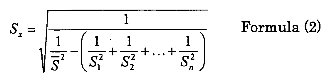 where
where S shows the total effective sectional area of the picking device
10; S1, S2, ..., Sn shows the effective sectional areas of the sub-nozzle side
pipes 40 and connectors 54, 58, 74; and Sx shows the effective sectional
area of the electromagnetic switching valve 38, respectively. Incidentally,
the effective sectional area Sx of the electromagnetic switching valve 38
does not include the effective sectional area of a portion where the
connectors 54 and 58 are to be inserted.
The result of the calculation of Formula (2) is shown in Fig. 4. In Fig.
4, the line 104 shows the pressure loss, and the line 105 shows the flow
rate of the compressed air, respectively. From Fig. 4, it is understood that
a range with a great flow rate of the compressed air and a small pressure
loss of the compressed area is where the effective area Sx of the
electromagnetic switching valve 38 is between 5 mm2 and 15 mm2, both
inclusive.
The time for exhausting the residual pressure and the flow rate,
respectively, of the compressed air of the sub-nozzle unit 34, when the
content volume of the third fluid channel K3 from the valve seat opening 72
of the electromagnetic switching valve 38 to the input end 22b of the
sub-nozzle 22 were variously changed, were measured. The conditions for
experiment and the method of measurement were decided as follows.
As a test device, a plurality of picking devices 10 provided with
various third fluid channels K3 having different content volumes were
produced to measure the flow rate and pressure loss of the compressed air
of the picking devices 10.
As for the picking devices 10 relative to respective content volumes of
the third fluid channels K3, two kinds of them were prepared in which the
lengths and inner diameters of the sub-nozzle side pipes 40 or the
electromagnetic switching valves 38 were changed.
The set value of the supply pressure of the pressure regulator 46 was
made a constant value (0.5 MPa) throughout the present experiment 3-1
and not changed halfway.
In this experiment 3-1, the time for exhausting the residual pressure,
after finishing of jetting of the sub-nozzle unit 34 when the content volume
of the sub-nozzle unit 34 was varied, was measured.
The time for exhausting the residual pressure was computed, using a
memory which stores signals of the electromagnetic switching valve 38 and
signals of nozzle side pressure sensor 82, from their measured values.
The time for exhausting the residual pressure was defined as a time
from when a closing output (stopping electricity to an exciting coil 62, i.e.,
turning off the exciting current) is commanded to the electromagnetic
switching valve 38 till when the value of the nozzle side pressure sensor 82
is lowered to 50% of the maximum pressure before the command for the
closing output (See Fig. 5). And the time for exhausting the residual
pressure of test devices of which the third fluid channels K3 have the same
content volume is measured respectively, the averaged value of the times
for exhausting the residual pressure of the test devices of which the content
volumes of the third fluid channels K3 are the same was defined as the
time for exhausting the residual pressure relative to the content volume.
The relation between the content volumes of the third fluid channels
K3 and the measured times for exhausting the residual pressure are shown
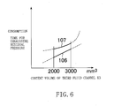
by a line 106 in Fig. 6.
The greater the content volume of the third fluid channel K3, the
longer the time for exhausting the residual pressure. The reason for this
is considered: the greater the content volume of the third fluid channel K3
becomes, the exhaustion amount of the compressed air remaining within
the fluid channel increases. Consequently, the smaller the content
volumes of the third fluid channel K3, the smaller the consumption of the
compressed air. In other words, the residual pressure jetting amount (the
residual pressure exhaust amount after the compressed air jetting ended),
which the compressed air remaining within the fluid channel K3 jets from
the sub-nozzle 22, decreases.
In order to measure the consumption of the compressed air of the
picking device 10, test devices having the content volumes of the third fluid
channels K3 in the above-mentioned experiment 3-1 were produced and
attached to looms, and actual weaving was carried out. The pressure of
the compressed air from the pressure regulator 46 was set at an optimum
value at which suitable jetting for weft insertion can be obtained from the
sub-nozzle 22 relative to two test devices of which the content volumes from
the third fluid channels K3 are the same.
As the set values of the looms, the kind of the weft selected was
polyester 84dtex, the width of the cloth was 337 cm, and the rotation
frequency of the main shaft of the loom was 750 rpm.
For measuring the consumption of the compressed air, the
consumption of the compressed air of all the sub-nozzles during operation
of the looms was measured, similarly to the experiment 1-3. The total of
the measured consumption was made the consumption of the compressed
air.
The relation between the content volume of the third fluid channel K3
and the measured consumption of the compressed air is shown by a line
107 in Fig. 6.
It is recognized that, when the content volume of the third fluid
channel K3 exceeds 3000 mm3, the consumption of the compressed air
rapidly increases. Presumably, this is because some factors (e.g., the
effective sectional area) other than the content volume of the third fluid
channel K3 influences not a little.
To give an example of the data obtained during this experiment, the
consumption of the compressed air was 65.8 Nm3/H when the content
volume of the third fluid channel K3 was 3100 mm3 and when the content
volume of the fourth fluid channel K4 was 1000 mm3. On the other hand,
the consumption of the compressed air was 59.5 Nm3/H when the content
volume of the third fluid channel K3 was 2500 mm3 and when the content
volume of the fourth fluid channel K4 was 520 mm3, in the present
invention. When these two consumption amounts of the compressed air
are compared, it is understood that the latter is reduced by 10.5 % from the
former.
As a result of experiments 3-1 and 3-2, as shown in Fig. 6, the smaller
the content volume of the third fluid channel K3, the smaller the
consumption of the compressed air. The content volume is preferably 3000
mm3 or less.
To make the content volume of the third fluid channel K3 small, the
inner diameter of the sub-nozzle side pipe 40 should be small; however, due
to such a problem as a limit in strength of the sub-nozzle side pipe 40 and a
pressure loss of the sub-nozzle side pipe 40, there is a lower limit of the
inner diameter of the sub-nozzle side pipe 40. As a result of the inventors'
study, the lower limit of the content volume of the third fluid channel K3
was set at 2000 mm3.
It is, therefore, understood that the content volume of the third fluid
channel K3 from the valve body side end of the valve seat opening 72 of the
electromagnetic switching valve 38 to the input end 22b of the sub-nozzle
22 is preferably between 2000 mm3 and 3000 mm3, both inclusive.
The fourth fluid channel K4 from the valve seat opening 72 of the
electromagnetic switching valve 38 to the output port 56 of the
electromagnetic switching valve 38 is a part of the third fluid channel K3.
So, by subtracting the content volumes of the sub-nozzle side pipe 40 and
connectors 58, 74 from the content volume of the third fluid channel K3,
the content volume from the valve body-side end of the valve seat opening
72 of the electromagnetic switching valve 38 to the output port 56 can be
obtained. That is to say, by using Formula (3), the range of the content
volume (X-axis in Fig. 6) of the third fluid channel K3 obtained by
experiments 3-1 and 3-2 is converted into the content volume of the fourth
fluid channel K4 from the valve body side end of the valve seat opening 72
of the electromagnetic switching valve 38 to the output port 56 of the
electromagnetic switching valve 38.
V x = V -( V 1 +V 2 +···+V n )
where V shows the content volume of the third fluid channel K3
from the valve body side end of the valve seat opening 72 of the
electromagnetic switching valve 38 to the input end 22b of the sub-nozzle
22; V1, V2, ..., Vn show the content volumes of the sub-nozzle side pipe 40
and the connectors 58, 74; and Vx shows the content volume from the valve
body side end of the valve seat opening 72 of the electromagnetic switching
valve 38 to the output port 56. Incidentally, the content volume Vx of the
electromagnetic valve 38 does not include the content volume of a portion
where the output side connector 58 is to be inserted.
In Fig. 7, the consumption of the compressed air relative to the
content volume provided by Formula (3) from the valve body side end of the
valve seat opening 72 of the electromagnetic switching valve 38 to the
output port 56 of the electromagnetic switching valve 38 is shown by a line
108. The proper range of the content volume Vx of the fourth fluid channel
K4 is considered to be 600 mm3 or less.
The consumption of the compressed air is reduced also by constituting
a picking device and an electromagnetic switching valve which satisfy both
the effective sectional area of the first fluid channel K1 and the content
volume of the third fluid channel K3 as obtained in the above.
Likewise, the consumption of the compressed air is reduced also by
constituting a picking device and an electromagnetic switching valve which
satisfy both the effective sectional area of the second fluid channel K2 and
the content volume of the fourth fluid channel K4 as obtained in the above.
Likewise, the consumption of the compressed air is reduced also by
constituting a picking device and an electromagnetic switching valve which
satisfy both the effective sectional areas of the first and second fluid
channels K1, K2 and the content volumes of the third and fourth fluid
channels K3, K4 as obtained in the above.
The foregoing picking devices can be applied to, besides the
compressed air, compressed fluid having a similar property to the
compressed air, as a result of which the consumption of the compressed
fluid is reduced.
The present invention is not limited to the above embodiments and
can be variously changed without departing from its spirit.
Claims (6)
- A picking device (10) of a loom comprising:wherein the effective sectional area of a fluid channel (K1) from a fluid outlet (48) of said fluid supply source (36) to an input end (22b) of said sub-nozzle (22) of said pipe (40) is between 2.5 mm2 and 3.5 mm2, both inclusive.at least one of sub-nozzle units (34) in which a sub-nozzle (22) and an electromagnetic switching valve (38) are communicated in one-to-one relationship through a pipe (40); anda fluid supply source (36) for supplying a compressed fluid to said electromagnetic switching valve (38);
- A picking device (10) of a loom comprising:wherein the effective sectional area of a fluid channel (K2) from an input port (52) of said electromagnetic switching valve (38) to an output port (56) of said electromagnetic switching valve (38) is between 5 mm2 and 15 mm2, both inclusive.at least one of sub-nozzle units (34) in which a sub-nozzle (22) and an electromagnetic switching valve (38) are communicated in one-to-one relationship through a pipe (40);
- A picking device (10) of a loom comprising:wherein the content volume of a fluid channel (K3) from the valve body side end of the valve seat opening (72) of said electromagnetic switching valve (38) to an input end (22b) of said sub-nozzle (22) is between 2000 mm3 and 3000 mm3, both inclusive.at least one of sub-nozzle units (34) in which a sub-nozzle (22) and an electromagnetic switching valve (38) are communicated in one-to-one relationship through a pipe (40);
- A picking device (10) of a loom comprising:wherein the content volume of a fluid channel (K4) from the valve body side end of the valve seat opening (72) of said electromagnetic switching valve (38) to an output port (56) of said electromagnetic switching valve (38) is 600 mm3 or less.at least one of sub-nozzle units (34) in which a sub-nozzle (22) and an electromagnetic switching valve (38) are communicated in one-to-one relationship through a pipe (40);
- A picking device (10) of a loom comprising:wherein the effective sectional area of a fluid channel (K1) from a fluid outlet (48) of said fluid supply source (36) to an input end (22b) of said sub-nozzle (22) of said pipe (40) is between 2.5 mm2 and 3.5 mm2, both inclusive, andat least one of sub-nozzle units (34) in which a sub-nozzle (22) and an electromagnetic switching valve (38) are communicated in one-to-one relationship through a pipe (40); anda fluid supply source (36) for supplying a compressed fluid to said electromagnetic switching valve (38);
wherein the content volume of a fluid channel (K3) from the valve body side end of the valve seat opening (72) of said electromagnetic switching valve (38) to an input end (22b) of said sub-nozzle (22) is between 2000 mm3 and 3000 mm3, both inclusive. - A picking device (10) of a loom comprising:wherein the effective sectional area of a fluid channel (K2) from an input port (52) of said electromagnetic switching valve (38) to an output port (56) of said electromagnetic switching valve (38) is between 5 mm2 and 15 mm2, both inclusive, andat least one of sub-nozzle units (34) in which a sub-nozzle (22) and an electromagnetic switching valve (38) are communicated in one-to-one relationship through a pipe (40);
wherein the content volume of a fluid channel (K4) from the valve body side end of the valve seat opening (72) of said electromagnetic switching valve (38) to an output port (56) of said electromagnetic switching valve (38) is 600 mm3 or less.
Applications Claiming Priority (3)
| Application Number | Priority Date | Filing Date | Title |
|---|---|---|---|
| JP2002251153 | 2002-08-29 | ||
| JP2002251153A JP2004091936A (en) | 2002-08-29 | 2002-08-29 | Weaving weft insertion device |
| PCT/JP2003/009869 WO2004020716A1 (en) | 2002-08-29 | 2003-08-04 | Picking device of weaving machine |
Publications (2)
| Publication Number | Publication Date |
|---|---|
| EP1536048A1 true EP1536048A1 (en) | 2005-06-01 |
| EP1536048A4 EP1536048A4 (en) | 2008-04-30 |
Family
ID=31972667
Family Applications (1)
| Application Number | Title | Priority Date | Filing Date |
|---|---|---|---|
| EP03791191A Withdrawn EP1536048A4 (en) | 2002-08-29 | 2003-08-04 | DEVICE FOR PICKING UP A WEAVING |
Country Status (5)
| Country | Link |
|---|---|
| EP (1) | EP1536048A4 (en) |
| JP (1) | JP2004091936A (en) |
| KR (1) | KR20040048975A (en) |
| CN (1) | CN1606637A (en) |
| WO (1) | WO2004020716A1 (en) |
Families Citing this family (2)
| Publication number | Priority date | Publication date | Assignee | Title |
|---|---|---|---|---|
| JP2010264061A (en) * | 2009-05-14 | 2010-11-25 | Fujifilm Corp | Internal pressure detecting device, internal pressure detecting method and endoscope device for expansion / contraction member |
| JP7429095B2 (en) * | 2018-11-19 | 2024-02-07 | 株式会社豊田自動織機 | air jet loom |
Family Cites Families (7)
| Publication number | Priority date | Publication date | Assignee | Title |
|---|---|---|---|---|
| EP0023928B1 (en) * | 1979-08-08 | 1983-05-18 | GebràDer Sulzer Aktiengesellschaft | Nozzle arrangement for a jet loom |
| JPH05222648A (en) * | 1992-02-07 | 1993-08-31 | Asahi Chem Ind Co Ltd | Weft-inserting device of air jet loom |
| BE1006981A3 (en) * | 1993-04-06 | 1995-02-07 | Picanol Nv | INSERTION SYSTEM FOR WEAVING MACHINES. |
| JPH06306737A (en) * | 1993-04-19 | 1994-11-01 | Toyota Autom Loom Works Ltd | Weft-insertion controlling apparatus for jet loom |
| JPH1094769A (en) * | 1996-09-20 | 1998-04-14 | Smc Corp | Blowing device bvr compressed air |
| JP3533861B2 (en) * | 1997-01-13 | 2004-05-31 | 株式会社豊田自動織機 | Method and apparatus for setting weft insertion timing in jet loom |
| JP2000096390A (en) * | 1998-09-10 | 2000-04-04 | Toyota Autom Loom Works Ltd | Air-jetting device in weaving machine |
-
2002
- 2002-08-29 JP JP2002251153A patent/JP2004091936A/en active Pending
-
2003
- 2003-08-04 CN CNA03801761XA patent/CN1606637A/en active Pending
- 2003-08-04 WO PCT/JP2003/009869 patent/WO2004020716A1/en not_active Ceased
- 2003-08-04 EP EP03791191A patent/EP1536048A4/en not_active Withdrawn
- 2003-08-04 KR KR10-2004-7005924A patent/KR20040048975A/en not_active Abandoned
Also Published As
| Publication number | Publication date |
|---|---|
| JP2004091936A (en) | 2004-03-25 |
| CN1606637A (en) | 2005-04-13 |
| EP1536048A4 (en) | 2008-04-30 |
| WO2004020716A1 (en) | 2004-03-11 |
| KR20040048975A (en) | 2004-06-10 |
Similar Documents
| Publication | Publication Date | Title |
|---|---|---|
| CN105986351A (en) | Weft insertion control method and weft insertion apparatus in air jet loom | |
| EP2330239A1 (en) | Tuck-in method and tuck-in device for shuttleless loom | |
| CN102031620A (en) | Weft insertion device of air-jet loom | |
| EP2014808B1 (en) | Weft insertion nozzle | |
| EP2476788A2 (en) | Weaving method for air jet loom | |
| KR100908669B1 (en) | Constant pressure liquid spray | |
| CN101994201B (en) | Weft holding device in a jet pick loom | |
| JP2004091936A (en) | Weaving weft insertion device | |
| US3977442A (en) | Fluid pressure control device for shuttleless weaving loom | |
| JP5276262B2 (en) | Weft insertion method and weft insertion device in water jet loom | |
| EP4163428B1 (en) | Weft insertion device for air jet loom | |
| CN111197195B (en) | Air jet loom | |
| CN101387037A (en) | Method for regulating the pressure in a loom and loom with a pressure regulation system | |
| CN220945896U (en) | Glaze feeding mechanism and glaze spraying equipment | |
| JP2003213544A (en) | Picking motion in jet loom | |
| US5746256A (en) | Method and apparatus for a controlled pneumatic removal of a faulty weft thread in an air jet loom | |
| CN210159889U (en) | Pressure reducing device and dispensing controller with same | |
| EP2765229B1 (en) | Air jet loom with a display device | |
| CN102051754A (en) | Air control system for inserting a weft yarn in a pneumatic weaving loom | |
| JP2006169657A (en) | Weft insertion device in water jet loom | |
| CN119800580A (en) | Weft insertion device of air jet loom | |
| CN222846935U (en) | Energy-saving weft insertion system of air jet loom | |
| JPH0949148A (en) | Weft inserting control device in jet loom | |
| JP2000096390A (en) | Air-jetting device in weaving machine | |
| CN101037824B (en) | Air jet loom |
Legal Events
| Date | Code | Title | Description |
|---|---|---|---|
| PUAI | Public reference made under article 153(3) epc to a published international application that has entered the european phase |
Free format text: ORIGINAL CODE: 0009012 |
|
| 17P | Request for examination filed |
Effective date: 20040429 |
|
| AK | Designated contracting states |
Kind code of ref document: A1 Designated state(s): AT BE BG CH CY CZ DE DK EE ES FI FR GB GR HU IE IT LI LU MC NL PT RO SE SI SK TR |
|
| AX | Request for extension of the european patent |
Extension state: AL LT LV MK |
|
| DAX | Request for extension of the european patent (deleted) | ||
| A4 | Supplementary search report drawn up and despatched |
Effective date: 20080331 |
|
| STAA | Information on the status of an ep patent application or granted ep patent |
Free format text: STATUS: THE APPLICATION IS DEEMED TO BE WITHDRAWN |
|
| 18D | Application deemed to be withdrawn |
Effective date: 20080628 |