EP1535849A2 - Box comprising a display tray and detachable cover - Google Patents
Box comprising a display tray and detachable cover Download PDFInfo
- Publication number
- EP1535849A2 EP1535849A2 EP04256987A EP04256987A EP1535849A2 EP 1535849 A2 EP1535849 A2 EP 1535849A2 EP 04256987 A EP04256987 A EP 04256987A EP 04256987 A EP04256987 A EP 04256987A EP 1535849 A2 EP1535849 A2 EP 1535849A2
- Authority
- EP
- European Patent Office
- Prior art keywords
- box
- cover
- weakness
- line
- panel
- Prior art date
- Legal status (The legal status is an assumption and is not a legal conclusion. Google has not performed a legal analysis and makes no representation as to the accuracy of the status listed.)
- Withdrawn
Links
Images


Classifications
-
- B—PERFORMING OPERATIONS; TRANSPORTING
- B65—CONVEYING; PACKING; STORING; HANDLING THIN OR FILAMENTARY MATERIAL
- B65D—CONTAINERS FOR STORAGE OR TRANSPORT OF ARTICLES OR MATERIALS, e.g. BAGS, BARRELS, BOTTLES, BOXES, CANS, CARTONS, CRATES, DRUMS, JARS, TANKS, HOPPERS, FORWARDING CONTAINERS; ACCESSORIES, CLOSURES, OR FITTINGS THEREFOR; PACKAGING ELEMENTS; PACKAGES
- B65D5/00—Rigid or semi-rigid containers of polygonal cross-section, e.g. boxes, cartons or trays, formed by folding or erecting one or more blanks made of paper
- B65D5/42—Details of containers or of foldable or erectable container blanks
- B65D5/44—Integral, inserted or attached portions forming internal or external fittings
- B65D5/52—External stands or display elements for contents
-
- B—PERFORMING OPERATIONS; TRANSPORTING
- B65—CONVEYING; PACKING; STORING; HANDLING THIN OR FILAMENTARY MATERIAL
- B65D—CONTAINERS FOR STORAGE OR TRANSPORT OF ARTICLES OR MATERIALS, e.g. BAGS, BARRELS, BOTTLES, BOXES, CANS, CARTONS, CRATES, DRUMS, JARS, TANKS, HOPPERS, FORWARDING CONTAINERS; ACCESSORIES, CLOSURES, OR FITTINGS THEREFOR; PACKAGING ELEMENTS; PACKAGES
- B65D5/00—Rigid or semi-rigid containers of polygonal cross-section, e.g. boxes, cartons or trays, formed by folding or erecting one or more blanks made of paper
- B65D5/02—Rigid or semi-rigid containers of polygonal cross-section, e.g. boxes, cartons or trays, formed by folding or erecting one or more blanks made of paper by folding or erecting a single blank to form a tubular body with or without subsequent folding operations, or the addition of separate elements, to close the ends of the body
- B65D5/16—Rigid or semi-rigid containers of polygonal cross-section, e.g. boxes, cartons or trays, formed by folding or erecting one or more blanks made of paper by folding or erecting a single blank to form a tubular body with or without subsequent folding operations, or the addition of separate elements, to close the ends of the body the tubular body being formed with an aperture or removable portion arranged to allow removal or insertion of contents through one or more sides
-
- B—PERFORMING OPERATIONS; TRANSPORTING
- B65—CONVEYING; PACKING; STORING; HANDLING THIN OR FILAMENTARY MATERIAL
- B65D—CONTAINERS FOR STORAGE OR TRANSPORT OF ARTICLES OR MATERIALS, e.g. BAGS, BARRELS, BOTTLES, BOXES, CANS, CARTONS, CRATES, DRUMS, JARS, TANKS, HOPPERS, FORWARDING CONTAINERS; ACCESSORIES, CLOSURES, OR FITTINGS THEREFOR; PACKAGING ELEMENTS; PACKAGES
- B65D5/00—Rigid or semi-rigid containers of polygonal cross-section, e.g. boxes, cartons or trays, formed by folding or erecting one or more blanks made of paper
- B65D5/42—Details of containers or of foldable or erectable container blanks
- B65D5/54—Lines of weakness to facilitate opening of container or dividing it into separate parts by cutting or tearing
- B65D5/5445—Lines of weakness to facilitate opening of container or dividing it into separate parts by cutting or tearing for dividing a tubular body into separate parts
Definitions
- the present invention relates to boxes comprising a detachable cover and a display tray made from a single sheet of material, forming such a box from a single flat blank, a flat blank for making into such a box and a method of detaching a cover from such a box.
- FR 2 713 597 discloses a box that is made from a single flat piece of material.
- the box includes a cover and a display tray that are connected together by lines of weakness. Goods are transported in the box and, when the goods are to be displayed, the cover is tilted upwardly in a pivotal movement to rip the cover off the box by tearing the lines of weakness.
- the inner sides of the box are loose and can swing into the interior of the box making it difficult to load goods.
- EP 0 763 473 has attempted to solve this problem by gluing or stapling facing surfaces of the tray and cover together. This involves an extra manufacturing stage and increases the cost of the box. In addition, when the cover is ripped off, in a pivotal movement, the display tray may become damaged and the contents may also be damaged or disturbed as may be the case with the box of the French publication.
- both of the prior boxes suffer from the fact that the covers are attached to the trays by a very small extent of weakened portion. Consequently they may fail when being folded as the weakened portions are likely to tear prematurely. This tearing is exacerbated as the weakened portions are required to be folded through 180° when assembling the blank into a box and with a downwards force being exerted on the horizontal folds.
- Both of the above boxes suffer from having relatively weak side walls that render them likely to buckle when they are stacked upon each other whether stacking occurs of the complete box or whether stacking is of display trays only.
- a box comprises a display tray and a cover made from a single sheet of material, the cover being detachable from the tray by tearing occurring along at least one line of weakness in which the line of weakness extends upwardly.
- a box comprises a display tray and a cover made from a single piece of material, the cover being detachable from the tray by tearing occurring along at least one line of weakness, the box including a layer of at least part of one upwardly extending wall being defined by part of the cover and part of the display tray which wall is arranged to be formed by folding the blank about folds which, in use, will be upwardly extending folds.
- the line of weakness may be spaced from the side or side corners of the box.
- the present invention also includes a method of forming a box from a single flat blank to form a cover and a display tray, the method comprising folding the blank so that the tray and the cover include at least one line of weakness that enables the cover to be detached from the tray, which line extends upwardly.
- the present invention also includes a method of forming a box from a single flat blank comprising folding the blank such that at least part of at least one upwardly extending wall is defined by the tray and the cover by folding the blank about what, in use, will be an upwardly extending fold.
- a flat blank of material including fold lines and at least one line of weakness, the blank being foldable to form a box comprising a display tray and a cover in which the cover is detachable and in which the line of weakness is arranged, in use, to extend upwardly.
- the present invention further includes a flat blank of material including fold lines and at least one line of weakness, the blank being foldable to form a box comprising a display tray and a cover in which the cover is detachable, the blank being foldable such that at least one wall that, in use, extends upwardly is at least partly defined by the tray and the cover by folds of the tray and cover that, in use, will extend upwardly.
- a box comprises a display tray and a cover made from a single sheet of material, with the cover being detachable from the tray by tearing occurring along at least one line of weakness, the tray and cover both including at least one layer extending along at least part of one upwardly extending wall of the box, with the inner of those layers mechanically engaging with another part of the box to inhibit movement of that inner layer inwardly into the space defined by the box.
- the inner layer may mechanically engage with another part of the box at at least two or three spaced locations such as the base region or a side portion or an upper region or spaced upper regions such as opposed side regions or any combination thereof. Such engagement may be by means of at least one tab.
- the inner layer may include a tab arranged to engage with a slot.
- the inner layer may be part of the cover.
- the inner layer may include a fold at at least one edge which may comprise a 180° or, alternatively or additionally 90° fold.
- the tab may be at an opposed edge.
- the inner layer may include two further tabs, each arranged to engage with a slot at a respective spaced location.
- the tabs may be located on opposing sides of the inner layer.
- the box may be at least one opening in the box adjacent to a line of weakness whereby, in use, an operative may engage with a layer inwardly of the opening to push the inner layer inwards and thereby detach the parts at that line of weakness.
- the line of weakness may be in the region of the base of the box and, alternatively or additionally may be in the region of the mechanical engagement.
- the opening or openings may be in the display tray. The operative may be required to push through openings in two layers to engage a layer inwards of the opening.
- the box may include the inner layer being retained in position at at least one edge and preferably at at least two edges and those edges may be adjacent to each other. At least one and preferably two edges of the inner layer, which may be adjacent edges, may be free edges, unconnected to other parts of the box.
- the box may include at least two layers extending at least part and preferably the whole depth of the box at at least part of one upwardly extending wall.
- the box may include at least three layers extending at least part of the depth of the box and preferably all three may extend the whole depth of the box at at least one upwardly extending wall.
- each wall may be two different walls extending along at least part of the upwards extent with each wall having any of the above described features. Those walls may be opposing walls and may be side walls.
- the tray When the cover is detached from the tray, the tray may have at least one wall having at least two layers extending the complete depth of the wall along at least part of the extent of the wall. When the cover is detached from the tray, the tray may present clean die cut edges.
- At least part of the cover may be arranged to be removed by lifting the cover upwardly in a generally linear direction. At least part of the cover may be arranged to be removed or detached or both by lifting the cover in a generally upwardly extending direction.
- the present invention also includes a method of forming a box from a single flat blank to form a cover and a display tray, the method comprising folding the blank so that the tray and cover both include at least one upwardly extending wall having two layers extending at least part of the depth of the box, the inner layer of that wall being caused to mechanically engage with another part of the box to inhibit movement of that inner layer inwardly into the space defined by the box, the blank including at least one line of weakness to enable detachment of the cover from the tray.
- the method may comprise forming a box as herein referred to.
- a flat blank of material including fold lines and at least one line of weakness, the blank being foldable to form a box comprising a display tray and a cover in which the cover is detachable with at least one upwardly extending wall having two layers extending at least part of the depth of that wall over at least part of the extent of that wall with the inner layer of that wall mechanically engaging with another part of the box to inhibit movement of that wall inwardly into the space defined by the box.
- the blank may be arranged to be formed into a box as herein referred to or by a method as herein referred to or both.
- a box formed from a single piece of material, the box comprising a detachable cover and display tray, the box including at least two layers extending the complete depth of at least one upwardly extending wall over at least part of the extent of that wall.
- At least one layer may extend to the complete depth of the wall over the complete extent of the wall. At least two layers that extend the complete depth of the wall may also extend the complete width of the wall at at least one location and may so extend at the same location which may be at the upper region of that wall.
- the box may be arranged to leave the display tray with at least one wall having at least two layers extending the complete depth of the wall over at least part of the extent of that wall when the cover is removed.
- the box may have two upwardly extending walls each having any of the features as herein referred to. These walls may be opposed walls and may comprise side walls.
- the present invention also includes a stack of such boxes or stack of display trays of at least 5 or at least 10 deep.
- the present invention also includes a method of making a box from a flat single piece of material comprising folding the material to form a box having a display tray and a detachable cover, the folds forming a box having at least one upwardly extending wall having at least two layers extending the complete depth of the box over at least part of the extent of that wall.
- the two layers that extend the complete depth of the wall may be formed by folding the blank about an upwardly extending fold which may be located at a corner region of the box.
- the inner layer of the two layers that extend the complete depth of the box may include a weakened portion which can be torn to allow one part to be removed with the other part defining at least part of the tray.
- the weakened portion may be spaced from the side or side corners of the box. The weakened portion may extend upwardly.
- the method may comprise making a box as herein referred to.
- a flat blank of material provided with folds whereby, when the blank is folded, a box comprising a detachable cover and display tray is provided with at least one upwardly extending wall having two layers extending the complete depth of the wall over at least part of the extent of that wall.
- the present invention also includes a flat blank provided with folds whereby, when the blank is folded a box as herein referred to is formed.
- a box formed from a single piece of material comprises a display tray and a detachable cover, the cover being arranged to be detached from the display tray by pushing a layer to cause detachment along at least one line of weakness.
- the layer that is pushed may be arranged to have at least one line of weakness and preferably two spaced lines of weakness.
- the layer that is pushed may be an upwardly extending layer.
- the layer that is pushed may be accessed through at least one opening in another layer or layers.
- the layer that is pushed may be arranged to be pushed in the region of the line of weakness which may be located at a lower region of the box.
- the cover may be arranged to be detached by pushing two different layers, for instance at the same time to cause detachment along at least one line of weakness of each layer.
- the layers may be opposed layers and may be side layers. Each layer may have any of the herein referred to features.
- the cover may be arranged to be lifted upwardly in a generally linear direction after detachment of the cover to remove the cover from the display tray.
- a method of detaching a cover from a box formed from a single piece of material comprising a cover and a box comprises pushing at least one layer to cause detachment of the cover along a line of weakness.
- the present invention also includes a flat blank arranged to be formed into a box comprising a detachable cover and display tray, with the cover being arranged to be detached by pushing to cause detachment along at least one line of weakness in the flat blank.
- a box formed from a single piece of material comprises a display tray and a detachable cover, the cover being arranged to be detached from the display tray by pulling a layer to cause detachment along at least one line of weakness.
- the layer that is pulled may be arranged to have at least one line of weakness.
- the layer that is pulled may be an upwardly extending layer.
- the layer that is pulled may be arranged to be pulled in the region of the line of weakness which may be located at a lower region of the box.
- the layer that is pulled may be arranged to be pulled upwardly.
- a method of detaching a cover from a box formed from a single piece of material comprising a cover and a box comprises pulling at least one layer to cause detachment of the cover along a line of weakness.
- the method may comprise detaching a cover from a box as herein referred to.
- the present invention also includes a flat blank arranged to be formed into a box comprising a detachable cover and display tray, with the cover being arranged to be detached by pulling to cause detachment along at least one line of weakness in the flat blank.
- the present invention also includes a flat blank for making into a box as herein referred to.
- the flat blank or the single piece of material may comprise cardboard such as corrugated cardboard which may have a planar sheet secured to at least one and preferably both sides.
- the present invention includes any combination of the herein referred to features or limitations.
- the flat blank shown in Figure 1 includes two parts which comprise a box for carrying goods in transit.
- the two parts can later be separated to remove a cover and leave a display tray for the contents of the box.
- the display tray includes panels that will extend upwardly during use comprising a front wall 10 which is connected by parallel valley folds 12 and 14 on each side to side panels 16 and 18.
- the panel 18 is connected to a rear wall 20 by a parallel fold 22.
- Each of the upwardly extending panels is connected to panels that will form the base of the box. These connections are by way of valley folds 24, 26, 28 and 30 to base panels 32, 34, 36 and 38 respectively.
- Each side panel is connected to a further side panel 40 and 42 by valley folds 44 and 46.
- the top edge of the side panels 40 and 42 are defined by lines of weakness 44 and 46 at each side of those panels which include a projecting tab 48 and 50 formed by a cut in the material that does not quite extend to the sides of those panels.
- the rear wall 20 is defined, at its upper end, by a line of weakness 52 that extends in an arc, downwardly from the top of each end of the panel.
- the lines of weakness may be defined by a series of perforations. When the lines of weakness 44, 46 and 52 are separated, the panels so far described comprise the display tray.
- the cover comprises two side walls 54 and 56 that are connected to the side panels 40 and 42 respectively by the lines of weakness 44 and 46, which lines comprise a mountain fold when the flat blank is folded.
- the side walls 54 and 56 are connected to a front cover 58 by parallel folds 60 and 62 respectively.
- the top of the side panels 54 and 56 and the top of the front cover 58 are each connected to top panels 64, 66 and 68 by respective aligned valley folds 70, 72 and 74.
- the remaining top panel 76 is connected to the rear wall 20 by the line of weakness 52 and it includes a valley fold 78 in line with the folds 44 and 46.
- the top panel 76 also includes a small upper part of the rear walls in the portion 80 defined between the fold 78 and the line of weakness 52.
- a customer is supplied with the blank in a folded flat form as will now be described.
- the side panels 40 and 42 are moved through 180° about the folds 44 and 46 such that they lie against the side panels 16 and 18.
- the rear wall 20 is moved through 180° about the valley fold 22 to lie against part of the side panel 56.
- the side panels 16, 40 and 54 together with the panels 34 and 64 are moved through 90° about fold lines 12 and 60 such that the side panel 54 lies over and against the front panel 58 and part of the side panel 56.
- a tab 82 connected to the free edge of the side panel 16 by a valley fold 84 is then glued to either what will be the inwardly or outwardly facing surface of the rear panel 20 in the area shown by the dotted line 86 on the panel 20.
- FIG. 1 shows the compact construction.
- the box is assembled to form the upwardly extending side walls by moving the rear wall or panel 20 through 90° about the valley fold 22 and moving the side panels 16, 40 and 54 through 90° about the valley folds 12 and 60.
- the side walls are each of 3 ply thickness with, on one side, the panel 16 being outermost and with the panel 40 being sandwiched between the innermost panel 54 and the panel 16.
- the panel 42 is sandwiched between the innermost panel 56 and the outer panel 18.
- the panel 58 where it overlaps the front panel 10, is located inwards of that panel.
- At the rear there is just the single panel 20 and the panel 80 joined by the line of weakness 52.
- the base panels 32, 34, 36 and 38 are then moved through 90° about their valley folds with each panel being tucked over an adjacent panel at one side and under an adjacent panel at the other side to lock the base panels together.
- the side panels are held by the tabs 48 and 50, which extend downwardly in the plane of the side walls 40 and 42, being tucked into respective slots 88 and 90 extending along and just to each side of the fold lines 26 and 28 of the panels 16, 34 and 18, 36.
- the inner panels 54 and 56 are held apart at the forward end by the front panel 58 that is connected to each inner panel by a fold.
- the top surface of each panel 54 and 56 is free as are the rear vertical surfaces of each panel 54 and 56. Thus there may be some small space between those panels 54 and 40, and 56 and 42.
- the box can now be loaded through the open top. After loading the box is closed by the top panels 64, 66, 68 and 76 each being moved through 90° about their valley folds. Each panel is alternately tucked over and under an adjacent panel at each side to lock the panels in place.
- the display tray is then left with side walls of double thickness, held in place by the tabs 48 and 50, with the contents being visible through a cut out portion 142 at the front of the box and possibly through the top of the box, if another is not stacked on top.
- the boxes or display tray may be stacked at least 5 or at least 10 deep or more.
- Figure 5 shows a second embodiment of a flat blank including two parts which comprise a box for carrying goods in transit.
- the display tray includes panels that will extend upwardly during use comprising a front wall 210 which is connected by parallel valley folds 212 and 214 on each side to side panels 216 and 218.
- the panel 216 is connected to a rear wall 220 by a parallel fold 222.
- Each of the upwardly extending panels is connected to panels that will form the base of the box. These connections are by way of valley folds 224, 226, 228 and 230 to base panels 232, 234, 236 and 238 respectively.
- the front wall 210 is connected to a front panel 240 by valley fold 242.
- the top edge of the front wall 210 is defined by lines of weakness 244 that extend to the sides of the wall between which it is located a projecting tab 246 formed by a cut in the material.
- the rear wall 220 is defined, at its upper end, by spaced parallel lines of weakness 248, 250 that extend downwardly from the top, inwards of the ends of the panel and a cut edge 251 joining the lower ends of the lines of weakness 248, 250.
- the lines of weakness may be defined by a series of perforations. When the lines of weakness 244, 248 and 250 are separated, the panels so far described comprise the display tray.
- the cover comprises front panel 252 that is connected to the front panel 240 by the line of weakness 244, the line comprising a mountain fold when the flat blank is folded.
- the top of the front cover 252 is connected to top panel 254 by an aligned valley fold 256.
- a tab 258 is formed in the panel 252 by a cut edge 260 formed along the fold 256, a cut edge 261 extending parallel thereto and lines of weakness 262 and 264 extending therebetween.
- Top panels 266 and 268 are connected to the respective side walls 216 and 218 providing respective aligned valley folds 270 and 272.
- the remaining top panel 274 is connected to the rear wall by valley fold 276 in line with the folds 270 and 272.
- the valley folds 270, 272, and 276 are lines of weakness.
- the cover also includes a small upper part of the rear wall 220 in a portion 278 defined between the fold 276, the lines of weakness 248 and 250 and the cut edge 279.
- the portion 278 forms a tab.
- a customer is supplied with the blank in a folded flat form as will now be described.
- the front panel 240 is moved through 180° about the folds 242 and 244 such that it lies between the front wall 210 and the front panel 252 as shown in Figure 6.
- the rear wall 220 is then moved through 180° about the valley fold 222 to lie against part of the side panel 216.
- the side panel 218 is moved through 180° about fold line 214 such that the side panel 218 lies over and against the front panel 252 and part of the side panel 216.
- a tab 280 connected to the free edge of the rear wall 220 by a valley fold 282 is then glued to either what will be the inwardly or outwardly facing surface of the side panel 218 in the area shown by dotted line 284 on the panel 218.
- the box is usually supplied to a user in this form, as shown in Figure 6.
- the box can be delivered without any folds at the front such that the flat blank is only folded to enable the tab 280 to be secured to the region 284 of the panel 284.
- the box is assembled to form the upwardly extending side walls by moving the front wall or panel 210 through 90° about the valley fold 212 and moving the side panel 218 through 90° about the valley fold 214.
- base panels 232 and 238 are then moved through 90° about their valley folds.
- base panels 234 and 236 are moved through 90° about their valley folds.
- Tape 286 is applied to a lower portion of the rear wall 220, along the join between the base panels 234 and 236 and onto a lower portion of the front wall 210 to hold the base panels together.
- the front panel 252 is held by the tab 246, which extends downwardly in the plane of the front cover 252, being tucked into slot 288 extending along and just to each side of the fold line 224 of the panels 210 and 232.
- the top surface of the front panel 252 is held in place by means of tabs 290, which extend sideways in the plane of the front cover 252, and are tucked into slots 292 extending along and just to each side of the fold lines 212 and 214 of the panels 210 and 218, and panels 210 and 216.
- the front cover is held in the middle at its lower end and at either side at its upper end.
- the box can now be loaded through the open top.
- the box is closed by the top panels 254, 260, 268 and 274 each being moved through 90° about their valley folds.
- the front and rear top panels 254 and 274 are first folded over and then the side top panels 260 and 268 are folded over on top.
- Tape 294 is applied to a top portion of the rear wall 220, along the join between the side panels and onto a top portion of the front panel 252 to lock the panels in place.
- the assembled box is shown in Figure 7.
- a user inserts a finger through an opening 296 in the front panel 252 and either lifts upwardly or pulls the tab out and lifts upwardly.
- the opening 296 is formed directly below the tab 258.
- the upward movement of the finger is thus exerted on the tab 258 just below the respective lines of weakness 262 and 264 and causes detachment of the tab 258 from the panel 252.
- a user inserts a finger through an opening 298 in the rear wall 220 and lifts upwardly or pulls the tab out and lifts upwardly.
- the opening 298 is formed directly below the tab 278.
- the upward movement of the finger is thus exerted on the tab 278 just below the respective lines of weakness 248 and 250 and causes detachment of the tab 278 from the panel 220.
- the tab 258 and/or 278 may also tear away the tape 294 across the top of the box. This is enabled by the tape extending over ends of the box and being stuck to at least one of the tabs 258 or 278.
- the majority of the cover is removed by tearing the top panels 266, 268 and 274 along their respective lines on weakness 270, 272 and 276. This does not damage the remainder of the tray and does not disturb the contents of the tray.
- the remaining part of the cover, comprising the front panels 252 and 254 are removed by a user pulling vertically to tear the panels 252 and 254 off along the line of weakness 244.
- the display tray is then left with side walls 216 and 218, rear wall 220 and front wall 210 as shown in Figure 8.
- the contents of the box are visible through a cut out portion 300 at the front of the box and possibly through the top of the box, if another is not stacked on top.
- the breakaway features of the front panel 252 of the box may be additionally applied to the rear wall 220 to provide two open faces to the customer. This has a further benefit when stacking as the box has a double wall thickness extending the complete depth of the box at each corner region.
- the breakaway features of the front panel 252 may be applied to one or both side walls 216, 218 of the box.
- a third embodiment is shown in Figure 9.
- the tray comprises base panels 300 and 302 that, in use, are arranged to be folded under base panels 304 and 306 about valley folds 308, 310, 312 and 314.
- Side panels of the tray comprise a first end panel 316, a first side panel 318, an end panel 320, a second side panel 322 and a short front end panel 324. These are connected by parallel valley folds 326, 328, 300 and 332.
- the tray includes a top rear panel comprising first panel 334 that is connected to the rear panel 320 by a fold 336.
- a second panel 38 is connected to the first panel 334 by a valley fold 340 parallel to the fold 326.
- the detachable cover comprises a first side top cover 342 connected to the first side panel 318 by a weakened line 344 and a second side top cover 346 connected to this panel 322 by a weakened line 348.
- An end top panel 350 is connected to the panel 368 by a line of weakness 352 at the left, adjacent to the panel 324 that extends to the right, when viewed in the drawing, in a fold line to connect to a rear panel 354 of the removable part. That panel 358 is connected to the panel by a line of weakness 356.
- the blank is folded with the second panel 338 being folded downwardly and being glued to the first panel 334. Then the blank is folded through 180° about the fold 330 such that the panels 322, 324 and 354 lie against the panels 320, 318 and 316.
- a tab 358 projecting from the right hand end of the panel 354 is locked in an opening 360 extending either side of the fold 326.
- a further tab 362 on the base of the panel 354 is locked in an opening 364 in the base panel 300 extending to the fold 308.
- An end flap 366 extending to the left of the front panel 316 is then glued to the rear (when viewed in Figure 8) of the panel 322, as shown by the hatched area 368.
- a user of the box then folds the base panels 300 and 302 through 90° and then the base panels 304 and 306 90° with tape being used along the joint of the base sides of the panels 304 and 306 and possibly up each end panel 316 and 320. At the same time the folds 326,328, 30 and 322 are each moved through 90°.
- the box is then filled, with the panels 342, 334, 338, 386 and 350 extending upwards.
- the joined panels 334 and 328 are folded inwardly about 90° as is the panel 350 with the top panels 382 and 346 then being folded over about 90°.
- the box when ready to receive products and during transportation has a double wall thickness at the front provided by the panel 316 and the panels 354 and 324.
- the fold line 332 being spaced from the weakened line 356, there is no tendency for box failure as a result of side walls being folded about a line of weakness.
- the adjacent sides of the panels 342 and 346 then have tape stuck to them with that tape extending over the panel 354 at one end and the panel 320 at the other.
- the tape on top is ripped off. Then an operative stubs their fingers through adjacent weakened areas 368 in each top panel 342 and 346 and a coextensive opening 370 in the top panel 350.
- the panels 350, 342 and 346 are then gripped by a user and pulled upwardly initially to first cause detachment about the lines 352 and 356 and then rearwardly to continue detachment rearwardly along the weakened lines 344 and 348.
- Product can then be viewed and removed from the tray.
- the now free rear panels 344 and 348 may pop up about the fold line 336 to show product information above the height of product in the box. Removal and viewing are assisted by a recess 372 cut in the top of the panel 316.
- any of the boxes described may be made of corrugated paper or plastic board or any suitable material.
Abstract
Description
- The present invention relates to boxes comprising a detachable cover and a display tray made from a single sheet of material, forming such a box from a single flat blank, a flat blank for making into such a box and a method of detaching a cover from such a box.
- FR 2 713 597 discloses a box that is made from a single flat piece of material. The box includes a cover and a display tray that are connected together by lines of weakness. Goods are transported in the box and, when the goods are to be displayed, the cover is tilted upwardly in a pivotal movement to rip the cover off the box by tearing the lines of weakness. However, the inner sides of the box are loose and can swing into the interior of the box making it difficult to load goods.
- EP 0 763 473 has attempted to solve this problem by gluing or stapling facing surfaces of the tray and cover together. This involves an extra manufacturing stage and increases the cost of the box. In addition, when the cover is ripped off, in a pivotal movement, the display tray may become damaged and the contents may also be damaged or disturbed as may be the case with the box of the French publication.
- In addition, both of the prior boxes suffer from the fact that the covers are attached to the trays by a very small extent of weakened portion. Consequently they may fail when being folded as the weakened portions are likely to tear prematurely. This tearing is exacerbated as the weakened portions are required to be folded through 180° when assembling the blank into a box and with a downwards force being exerted on the horizontal folds.
- Both of the above boxes suffer from having relatively weak side walls that render them likely to buckle when they are stacked upon each other whether stacking occurs of the complete box or whether stacking is of display trays only.
- It is an object of the present invention to attempt to overcome at least one of the above or other disadvantages.
- According to a first aspect of the present invention, a box comprises a display tray and a cover made from a single sheet of material, the cover being detachable from the tray by tearing occurring along at least one line of weakness in which the line of weakness extends upwardly.
- According to a further aspect of the present invention, a box comprises a display tray and a cover made from a single piece of material, the cover being detachable from the tray by tearing occurring along at least one line of weakness, the box including a layer of at least part of one upwardly extending wall being defined by part of the cover and part of the display tray which wall is arranged to be formed by folding the blank about folds which, in use, will be upwardly extending folds.
- Any of the following statements or sub-statements may apply to any aspect of the invention.
- The line of weakness may be spaced from the side or side corners of the box.
- The present invention also includes a method of forming a box from a single flat blank to form a cover and a display tray, the method comprising folding the blank so that the tray and the cover include at least one line of weakness that enables the cover to be detached from the tray, which line extends upwardly.
- The present invention also includes a method of forming a box from a single flat blank comprising folding the blank such that at least part of at least one upwardly extending wall is defined by the tray and the cover by folding the blank about what, in use, will be an upwardly extending fold.
- Also included is a flat blank of material including fold lines and at least one line of weakness, the blank being foldable to form a box comprising a display tray and a cover in which the cover is detachable and in which the line of weakness is arranged, in use, to extend upwardly.
- The present invention further includes a flat blank of material including fold lines and at least one line of weakness, the blank being foldable to form a box comprising a display tray and a cover in which the cover is detachable, the blank being foldable such that at least one wall that, in use, extends upwardly is at least partly defined by the tray and the cover by folds of the tray and cover that, in use, will extend upwardly.
- According to one aspect of the present invention a box comprises a display tray and a cover made from a single sheet of material, with the cover being detachable from the tray by tearing occurring along at least one line of weakness, the tray and cover both including at least one layer extending along at least part of one upwardly extending wall of the box, with the inner of those layers mechanically engaging with another part of the box to inhibit movement of that inner layer inwardly into the space defined by the box.
- The inner layer may mechanically engage with another part of the box at at least two or three spaced locations such as the base region or a side portion or an upper region or spaced upper regions such as opposed side regions or any combination thereof. Such engagement may be by means of at least one tab.
- The inner layer may include a tab arranged to engage with a slot. The inner layer may be part of the cover.
- The inner layer may include a fold at at least one edge which may comprise a 180° or, alternatively or additionally 90° fold. The tab may be at an opposed edge.
- The inner layer may include two further tabs, each arranged to engage with a slot at a respective spaced location. The tabs may be located on opposing sides of the inner layer.
- There may be at least one opening in the box adjacent to a line of weakness whereby, in use, an operative may engage with a layer inwardly of the opening to push the inner layer inwards and thereby detach the parts at that line of weakness. There may be two such holes in the box spaced from each other which may be on the same upwardly extending layer. The line of weakness may be in the region of the base of the box and, alternatively or additionally may be in the region of the mechanical engagement. The opening or openings may be in the display tray. The operative may be required to push through openings in two layers to engage a layer inwards of the opening.
- The box may include the inner layer being retained in position at at least one edge and preferably at at least two edges and those edges may be adjacent to each other. At least one and preferably two edges of the inner layer, which may be adjacent edges, may be free edges, unconnected to other parts of the box.
- The box may include at least two layers extending at least part and preferably the whole depth of the box at at least part of one upwardly extending wall. The box may include at least three layers extending at least part of the depth of the box and preferably all three may extend the whole depth of the box at at least one upwardly extending wall.
- There may be two different walls extending along at least part of the upwards extent with each wall having any of the above described features. Those walls may be opposing walls and may be side walls.
- When the cover is detached from the tray, the tray may have at least one wall having at least two layers extending the complete depth of the wall along at least part of the extent of the wall. When the cover is detached from the tray, the tray may present clean die cut edges.
- At least part of the cover may be arranged to be removed by lifting the cover upwardly in a generally linear direction. At least part of the cover may be arranged to be removed or detached or both by lifting the cover in a generally upwardly extending direction.
- The present invention also includes a method of forming a box from a single flat blank to form a cover and a display tray, the method comprising folding the blank so that the tray and cover both include at least one upwardly extending wall having two layers extending at least part of the depth of the box, the inner layer of that wall being caused to mechanically engage with another part of the box to inhibit movement of that inner layer inwardly into the space defined by the box, the blank including at least one line of weakness to enable detachment of the cover from the tray.
- The method may comprise forming a box as herein referred to.
- According to a further aspect of the present invention there is provided a flat blank of material including fold lines and at least one line of weakness, the blank being foldable to form a box comprising a display tray and a cover in which the cover is detachable with at least one upwardly extending wall having two layers extending at least part of the depth of that wall over at least part of the extent of that wall with the inner layer of that wall mechanically engaging with another part of the box to inhibit movement of that wall inwardly into the space defined by the box.
- The blank may be arranged to be formed into a box as herein referred to or by a method as herein referred to or both.
- According to another aspect of the present invention there is provided a box formed from a single piece of material, the box comprising a detachable cover and display tray, the box including at least two layers extending the complete depth of at least one upwardly extending wall over at least part of the extent of that wall.
- At least one layer may extend to the complete depth of the wall over the complete extent of the wall. At least two layers that extend the complete depth of the wall may also extend the complete width of the wall at at least one location and may so extend at the same location which may be at the upper region of that wall.
- The box may be arranged to leave the display tray with at least one wall having at least two layers extending the complete depth of the wall over at least part of the extent of that wall when the cover is removed.
- The box may have two upwardly extending walls each having any of the features as herein referred to. These walls may be opposed walls and may comprise side walls.
- The present invention also includes a stack of such boxes or stack of display trays of at least 5 or at least 10 deep.
- The present invention also includes a method of making a box from a flat single piece of material comprising folding the material to form a box having a display tray and a detachable cover, the folds forming a box having at least one upwardly extending wall having at least two layers extending the complete depth of the box over at least part of the extent of that wall.
- The two layers that extend the complete depth of the wall may be formed by folding the blank about an upwardly extending fold which may be located at a corner region of the box.
- The inner layer of the two layers that extend the complete depth of the box may include a weakened portion which can be torn to allow one part to be removed with the other part defining at least part of the tray. The weakened portion may be spaced from the side or side corners of the box. The weakened portion may extend upwardly.
- The method may comprise making a box as herein referred to.
- According to a further aspect of the present invention there is provided a flat blank of material provided with folds whereby, when the blank is folded, a box comprising a detachable cover and display tray is provided with at least one upwardly extending wall having two layers extending the complete depth of the wall over at least part of the extent of that wall.
- The present invention also includes a flat blank provided with folds whereby, when the blank is folded a box as herein referred to is formed.
- According to another aspect of the present invention, a box formed from a single piece of material comprises a display tray and a detachable cover, the cover being arranged to be detached from the display tray by pushing a layer to cause detachment along at least one line of weakness.
- The layer that is pushed may be arranged to have at least one line of weakness and preferably two spaced lines of weakness.
- The layer that is pushed may be an upwardly extending layer.
- The layer that is pushed may be accessed through at least one opening in another layer or layers.
- The layer that is pushed may be arranged to be pushed in the region of the line of weakness which may be located at a lower region of the box.
- The cover may be arranged to be detached by pushing two different layers, for instance at the same time to cause detachment along at least one line of weakness of each layer. The layers may be opposed layers and may be side layers. Each layer may have any of the herein referred to features.
- The cover may be arranged to be lifted upwardly in a generally linear direction after detachment of the cover to remove the cover from the display tray.
- According to another aspect of the present invention, a method of detaching a cover from a box formed from a single piece of material comprising a cover and a box comprises pushing at least one layer to cause detachment of the cover along a line of weakness.
- The present invention also includes a flat blank arranged to be formed into a box comprising a detachable cover and display tray, with the cover being arranged to be detached by pushing to cause detachment along at least one line of weakness in the flat blank.
- According to another aspect of the present invention, a box formed from a single piece of material comprises a display tray and a detachable cover, the cover being arranged to be detached from the display tray by pulling a layer to cause detachment along at least one line of weakness.
- The layer that is pulled may be arranged to have at least one line of weakness.
- The layer that is pulled may be an upwardly extending layer.
- The layer that is pulled may be arranged to be pulled in the region of the line of weakness which may be located at a lower region of the box. The layer that is pulled may be arranged to be pulled upwardly.
- According to another aspect of the present invention, a method of detaching a cover from a box formed from a single piece of material comprising a cover and a box comprises pulling at least one layer to cause detachment of the cover along a line of weakness.
- The method may comprise detaching a cover from a box as herein referred to.
- The present invention also includes a flat blank arranged to be formed into a box comprising a detachable cover and display tray, with the cover being arranged to be detached by pulling to cause detachment along at least one line of weakness in the flat blank.
- The present invention also includes a flat blank for making into a box as herein referred to.
- The flat blank or the single piece of material may comprise cardboard such as corrugated cardboard which may have a planar sheet secured to at least one and preferably both sides.
- The present invention includes any combination of the herein referred to features or limitations.
- The invention can be carried into practice in various ways but one embodiment will now be described by way of example and with reference to the accompanying drawings, in which:-
- Figure 1 is a plan view of a flat blank to be made into a box comprising the display tray and the detachable cover, according to a first embodiment of the invention;
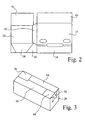
- Figure 2 is a front view of the box of Figure 1, ready for supply to a customer in a flat configuration;
- Figure 3 is a perspective view of the assembled box of Figure 1, and
- Figure 4 is a perspective view of the display tray of Figure 1, after removal of the cover;
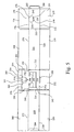
- Figure 5 is a plan view of a flat blank to be made into a box comprising the display tray and the detachable cover, according to a second embodiment of the invention;
- Figure 6 is a plan view of the flat blank of Figure 5, with the front panel glued in position;
- Figure 7 is a perspective view of the assembled box of Figure 5; and
- Figure 8 is a perspective view of the display tray of Figure 5, after removal of the cover.
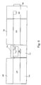
- Figure 9 is a plan view of a third embodiment showing a flat blank to be made into a box.
-
- The flat blank shown in Figure 1 includes two parts which comprise a box for carrying goods in transit. The two parts can later be separated to remove a cover and leave a display tray for the contents of the box.
- The display tray includes panels that will extend upwardly during use comprising a
front wall 10 which is connected by parallel valley folds 12 and 14 on each side toside panels panel 18 is connected to arear wall 20 by aparallel fold 22. Each of the upwardly extending panels is connected to panels that will form the base of the box. These connections are by way of valley folds 24, 26, 28 and 30 tobase panels further side panel side panels weakness tab rear wall 20 is defined, at its upper end, by a line ofweakness 52 that extends in an arc, downwardly from the top of each end of the panel. - The lines of weakness may be defined by a series of perforations. When the lines of
weakness - The cover comprises two
side walls 54 and 56 that are connected to theside panels weakness side walls 54 and 56 are connected to afront cover 58 byparallel folds side panels 54 and 56 and the top of thefront cover 58 are each connected totop panels top panel 76 is connected to therear wall 20 by the line ofweakness 52 and it includes avalley fold 78 in line with thefolds top panel 76 also includes a small upper part of the rear walls in theportion 80 defined between thefold 78 and the line ofweakness 52. - A customer is supplied with the blank in a folded flat form as will now be described. The
side panels folds side panels rear wall 20 is moved through 180° about the valley fold 22 to lie against part of theside panel 56. Theside panels panels fold lines front panel 58 and part of theside panel 56. Atab 82 connected to the free edge of theside panel 16 by avalley fold 84 is then glued to either what will be the inwardly or outwardly facing surface of therear panel 20 in the area shown by the dottedline 86 on thepanel 20. - Thus the customer is provided with a compact construction made from a single piece of material, which, typically, may comprise corrugated cardboard having planar sheets attached to each surface. Figure 2 shows the compact construction.
- The box is assembled to form the upwardly extending side walls by moving the rear wall or
panel 20 through 90° about thevalley fold 22 and moving theside panels panel 16 being outermost and with thepanel 40 being sandwiched between the innermost panel 54 and thepanel 16. On the other side wall thepanel 42 is sandwiched between theinnermost panel 56 and theouter panel 18. Thepanel 58, where it overlaps thefront panel 10, is located inwards of that panel. At the rear, there is just thesingle panel 20 and thepanel 80 joined by the line ofweakness 52. - The
base panels - The side panels are held by the
tabs side walls respective slots panels inner panels 54 and 56 are held apart at the forward end by thefront panel 58 that is connected to each inner panel by a fold. The top surface of eachpanel 54 and 56 is free as are the rear vertical surfaces of eachpanel 54 and 56. Thus there may be some small space between thosepanels - The box can now be loaded through the open top. After loading the box is closed by the
top panels - To convert the box into a display tray a user pushes their fingers through spaced
openings panels openings panels 54 and 56 and againstpanels weakness panels 54 and 56 from thepanels opening 100 extending below the line ofweakness 52 and pulling to tear thepanels - The display tray is then left with side walls of double thickness, held in place by the
tabs - With the double thickness side walls extending the complete depth, resistance to buckling is provided if one display tray is stacked upon another. Even greater resistance to buckling is provided if one box is stacked upon another as three side walls extending the complete depth are provided.
- The boxes or display tray may be stacked at least 5 or at least 10 deep or more.
- Figure 5 shows a second embodiment of a flat blank including two parts which comprise a box for carrying goods in transit.
- The display tray includes panels that will extend upwardly during use comprising a
front wall 210 which is connected by parallel valley folds 212 and 214 on each side toside panels panel 216 is connected to arear wall 220 by aparallel fold 222. Each of the upwardly extending panels is connected to panels that will form the base of the box. These connections are by way of valley folds 224, 226, 228 and 230 tobase panels front wall 210 is connected to afront panel 240 byvalley fold 242. - When viewing Figure 5, the top edge of the
front wall 210 is defined by lines ofweakness 244 that extend to the sides of the wall between which it is located a projectingtab 246 formed by a cut in the material. Therear wall 220 is defined, at its upper end, by spaced parallel lines ofweakness cut edge 251 joining the lower ends of the lines ofweakness - The lines of weakness may be defined by a series of perforations. When the lines of
weakness - The cover comprises
front panel 252 that is connected to thefront panel 240 by the line ofweakness 244, the line comprising a mountain fold when the flat blank is folded. When viewed in Figure 5, the top of thefront cover 252 is connected totop panel 254 by an alignedvalley fold 256. Atab 258 is formed in thepanel 252 by acut edge 260 formed along thefold 256, acut edge 261 extending parallel thereto and lines ofweakness Top panels respective side walls top panel 274 is connected to the rear wall byvalley fold 276 in line with thefolds rear wall 220 in aportion 278 defined between thefold 276, the lines ofweakness cut edge 279. Theportion 278 forms a tab. - A customer is supplied with the blank in a folded flat form as will now be described. The
front panel 240 is moved through 180° about thefolds front wall 210 and thefront panel 252 as shown in Figure 6. Therear wall 220 is then moved through 180° about thevalley fold 222 to lie against part of theside panel 216. Theside panel 218 is moved through 180° aboutfold line 214 such that theside panel 218 lies over and against thefront panel 252 and part of theside panel 216. Atab 280 connected to the free edge of therear wall 220 by avalley fold 282 is then glued to either what will be the inwardly or outwardly facing surface of theside panel 218 in the area shown by dottedline 284 on thepanel 218. - The box is usually supplied to a user in this form, as shown in Figure 6. In an alternative method of supply though, the box can be delivered without any folds at the front such that the flat blank is only folded to enable the
tab 280 to be secured to theregion 284 of thepanel 284. - The box is assembled to form the upwardly extending side walls by moving the front wall or
panel 210 through 90° about thevalley fold 212 and moving theside panel 218 through 90° about thevalley fold 214. - The
base panels base panels Tape 286 is applied to a lower portion of therear wall 220, along the join between thebase panels front wall 210 to hold the base panels together. - The
front panel 252 is held by thetab 246, which extends downwardly in the plane of thefront cover 252, being tucked intoslot 288 extending along and just to each side of thefold line 224 of thepanels front panel 252 is held in place by means oftabs 290, which extend sideways in the plane of thefront cover 252, and are tucked intoslots 292 extending along and just to each side of thefold lines panels panels - The box can now be loaded through the open top. After loading, the box is closed by the
top panels top panels top panels Tape 294 is applied to a top portion of therear wall 220, along the join between the side panels and onto a top portion of thefront panel 252 to lock the panels in place. The assembled box is shown in Figure 7. - To convert the box into a display tray a user inserts a finger through an
opening 296 in thefront panel 252 and either lifts upwardly or pulls the tab out and lifts upwardly. Theopening 296 is formed directly below thetab 258. The upward movement of the finger is thus exerted on thetab 258 just below the respective lines ofweakness tab 258 from thepanel 252. In the same manner, a user inserts a finger through anopening 298 in therear wall 220 and lifts upwardly or pulls the tab out and lifts upwardly. Theopening 298 is formed directly below thetab 278. The upward movement of the finger is thus exerted on thetab 278 just below the respective lines ofweakness tab 278 from thepanel 220. As thetab 258 and/or 278 is detached it may also tear away thetape 294 across the top of the box. This is enabled by the tape extending over ends of the box and being stuck to at least one of thetabs - Then the majority of the cover is removed by tearing the
top panels weakness front panels panels weakness 244. - The display tray is then left with
side walls rear wall 220 andfront wall 210 as shown in Figure 8. The contents of the box are visible through a cut outportion 300 at the front of the box and possibly through the top of the box, if another is not stacked on top. - The breakaway features of the
front panel 252 of the box may be additionally applied to therear wall 220 to provide two open faces to the customer. This has a further benefit when stacking as the box has a double wall thickness extending the complete depth of the box at each corner region. Alternatively and/or additionally, the breakaway features of thefront panel 252 may be applied to one or bothside walls - A third embodiment is shown in Figure 9.
- The tray comprises
base panels base panels first end panel 316, afirst side panel 318, anend panel 320, a second side panel 322 and a shortfront end panel 324. These are connected by parallel valley folds 326, 328, 300 and 332. The tray includes a top rear panel comprisingfirst panel 334 that is connected to therear panel 320 by afold 336. Asecond panel 38 is connected to thefirst panel 334 by avalley fold 340 parallel to thefold 326. - The detachable cover comprises a first side
top cover 342 connected to thefirst side panel 318 by a weakenedline 344 and a second sidetop cover 346 connected to this panel 322 by a weakenedline 348. An endtop panel 350 is connected to thepanel 368 by a line ofweakness 352 at the left, adjacent to thepanel 324 that extends to the right, when viewed in the drawing, in a fold line to connect to arear panel 354 of the removable part. Thatpanel 358 is connected to the panel by a line ofweakness 356. - To send the box to a customer the blank is folded with the
second panel 338 being folded downwardly and being glued to thefirst panel 334. Then the blank is folded through 180° about thefold 330 such that thepanels panels tab 358 projecting from the right hand end of thepanel 354 is locked in anopening 360 extending either side of thefold 326. Afurther tab 362 on the base of thepanel 354 is locked in anopening 364 in thebase panel 300 extending to thefold 308. Anend flap 366 extending to the left of thefront panel 316 is then glued to the rear (when viewed in Figure 8) of the panel 322, as shown by the hatchedarea 368. - A user of the box then folds the
base panels base panels panels end panel - The box is then filled, with the
panels panels panel 350 with thetop panels 382 and 346 then being folded over about 90°. It can be seen that the box, when ready to receive products and during transportation has a double wall thickness at the front provided by thepanel 316 and thepanels fold line 332 being spaced from the weakenedline 356, there is no tendency for box failure as a result of side walls being folded about a line of weakness. The adjacent sides of thepanels panel 354 at one end and thepanel 320 at the other. - To connect the box with a'display tray the tape on top is ripped off. Then an operative stubs their fingers through adjacent weakened
areas 368 in eachtop panel coextensive opening 370 in thetop panel 350. Thepanels lines lines - Product can then be viewed and removed from the tray. The now free
rear panels fold line 336 to show product information above the height of product in the box. Removal and viewing are assisted by arecess 372 cut in the top of thepanel 316. - It will be appreciated that any of the features of the different embodiments may be combined with each other or interchanged with each other.
- Any of the boxes described may be made of corrugated paper or plastic board or any suitable material.
- Attention is directed to all papers and documents which are filed concurrently with or previous to this specification in connection with this application and which are open to public inspection with this specification, and the contents of all such papers and documents are incorporated herein by reference.
- All of the features disclosed in this specification (including any accompanying claims, abstract and drawings), and/or all of the steps of any method or process so disclosed, may be combined in any combination, except combinations where at least some of such features and/or steps are mutually exclusive.
- Each feature disclosed in this specification (including any accompanying claims, abstract and drawings) may be replaced by alternative features serving the same, equivalent or similar purpose, unless expressly stated otherwise. Thus, unless expressly stated otherwise, each feature disclosed is one example only of a generic series of equivalent or similar features.
- The invention is not restricted to the details of the foregoing embodiment(s). The invention extends to any novel one, or any novel combination, of the features disclosed in this specification (including any accompanying claims, abstract and drawings), or to any novel one, or any novel combination, of the steps of any method or process so disclosed.
Claims (12)
- A box comprising a display tray and a cover made from a single sheet of material, the cover being detachable from the tray by tearing occurring along at least one line of weakness in which the line of weakness extends upwardly.
- A box as claimed in Claim 1 including at least one opening in the box adjacent to the line of weakness whereby, in use, an operative may engage with a layer inwardly of the opening to push the inner layer inwards and thereby detach the parts at that line of weakness.
- A box as claimed in Claim 1 or 2 in which the line of weakness extends vertically.
- A box as claimed in any preceding claim in which the line of weakness is spaced from a side corner of the box.
- A box as claimed in any preceding claim in which one side wall is defined at least in part by an inner layer and an outer layer and in which at least one edge of the inner layer at that wall is a free edge unconnected to other parts of the box.
- A box as claimed in Claim 5 in which at least two edges of the inner layer at that wall are free edges unconnected to other parts of the box.
- A box as claimed in Claim 6 in which the two edges of the inner layer that are free edges are adjacent edges.
- A box as claimed in any preceding claim including at least two layers extending the whole depth of the box at at least part of one upwardly extending wall.
- A box as claimed in any preceding claim in which, when the cover is detached from the tray, the tray has at least one wall having at least two layers extending the complete depth of the wall along at least part of the extent of the wall.
- A box as claimed in any preceding claim in which, at least part of the cover is arranged to be removed by lifting the cover upwardly in a generally linear direction.
- A method of forming a box from a single flat blank to form a cover and a display tray, the method comprising folding the blank so that the tray and the cover include at least one line of weakness that enables the cover to be detached from the tray that extends upwardly.
- A flat blank of material including fold lines and at least one line of weakness, the blank being foldable to form a box comprising a display tray and cover in which the cover is detachable, in which the line of weakness is arranged, in use, to extend upwardly.
Applications Claiming Priority (6)
| Application Number | Priority Date | Filing Date | Title |
|---|---|---|---|
| GB0327334A GB0327334D0 (en) | 2003-11-25 | 2003-11-25 | Boxes comprising a display tray and detachable cover |
| GB0327334 | 2003-11-25 | ||
| GB0413384 | 2004-06-16 | ||
| GB0413384A GB2408499A (en) | 2003-11-25 | 2004-06-16 | Boxes comprising a display tray and detachable cover |
| GB0417545 | 2004-08-06 | ||
| GB0417545A GB2408500B (en) | 2003-11-25 | 2004-08-06 | Boxes comprising a display tray and detachable cover |
Publications (2)
| Publication Number | Publication Date |
|---|---|
| EP1535849A2 true EP1535849A2 (en) | 2005-06-01 |
| EP1535849A3 EP1535849A3 (en) | 2008-10-29 |
Family
ID=34468186
Family Applications (1)
| Application Number | Title | Priority Date | Filing Date |
|---|---|---|---|
| EP04256987A Withdrawn EP1535849A3 (en) | 2003-11-25 | 2004-11-11 | Box comprising a display tray and detachable cover |
Country Status (1)
| Country | Link |
|---|---|
| EP (1) | EP1535849A3 (en) |
Cited By (4)
| Publication number | Priority date | Publication date | Assignee | Title |
|---|---|---|---|---|
| EP1967453A1 (en) | 2007-03-09 | 2008-09-10 | Saica Embalaje Centro, S.A. | One piece display box. |
| JP2012066825A (en) * | 2010-09-21 | 2012-04-05 | Lotte Co Ltd | Box with display board and paperboard for the same |
| NL2015206B1 (en) * | 2015-07-22 | 2017-02-08 | Smurfit Kappa Elcorr B V | Boxes and blanks for such boxes, and methods for forming blanks and boxes. |
| US11772842B2 (en) * | 2019-12-17 | 2023-10-03 | The Hershey Company | Package with reinforced lines of weakness for storage and transport |
Citations (4)
| Publication number | Priority date | Publication date | Assignee | Title |
|---|---|---|---|---|
| US3189251A (en) * | 1961-04-25 | 1965-06-15 | Int Paper Co | Container |
| DE20000449U1 (en) * | 2000-01-12 | 2000-04-27 | Thimm Verpackung Gmbh & Co | Foldable packaging |
| US6158579A (en) * | 1998-02-26 | 2000-12-12 | Inland Paperboard And Packaging, Inc. | Container with pop-up display header |
| US6189780B1 (en) * | 2000-04-03 | 2001-02-20 | Allen Kanter | Display container having integral reinforcement |
-
2004
- 2004-11-11 EP EP04256987A patent/EP1535849A3/en not_active Withdrawn
Patent Citations (4)
| Publication number | Priority date | Publication date | Assignee | Title |
|---|---|---|---|---|
| US3189251A (en) * | 1961-04-25 | 1965-06-15 | Int Paper Co | Container |
| US6158579A (en) * | 1998-02-26 | 2000-12-12 | Inland Paperboard And Packaging, Inc. | Container with pop-up display header |
| DE20000449U1 (en) * | 2000-01-12 | 2000-04-27 | Thimm Verpackung Gmbh & Co | Foldable packaging |
| US6189780B1 (en) * | 2000-04-03 | 2001-02-20 | Allen Kanter | Display container having integral reinforcement |
Cited By (4)
| Publication number | Priority date | Publication date | Assignee | Title |
|---|---|---|---|---|
| EP1967453A1 (en) | 2007-03-09 | 2008-09-10 | Saica Embalaje Centro, S.A. | One piece display box. |
| JP2012066825A (en) * | 2010-09-21 | 2012-04-05 | Lotte Co Ltd | Box with display board and paperboard for the same |
| NL2015206B1 (en) * | 2015-07-22 | 2017-02-08 | Smurfit Kappa Elcorr B V | Boxes and blanks for such boxes, and methods for forming blanks and boxes. |
| US11772842B2 (en) * | 2019-12-17 | 2023-10-03 | The Hershey Company | Package with reinforced lines of weakness for storage and transport |
Also Published As
| Publication number | Publication date |
|---|---|
| EP1535849A3 (en) | 2008-10-29 |
Similar Documents
| Publication | Publication Date | Title |
|---|---|---|
| US5622309A (en) | Carton for packaging cut sheets of paper | |
| AU2006260871B2 (en) | Corrugated cardboard box with open-work flaps and assembly of blanks for obtaining same | |
| US7669755B2 (en) | Carton with hinged lid | |
| US9783334B2 (en) | Shipping and display container | |
| MX2010010948A (en) | Set of cardboard blanks, box and method for making a box with such blanks. | |
| EP3296220A1 (en) | An improved opening system | |
| JP7107098B2 (en) | packaging box | |
| US20040232039A1 (en) | Multi-purpose shipping and display container | |
| EP1535849A2 (en) | Box comprising a display tray and detachable cover | |
| CN111498239B (en) | Lifting type fast assembling containing box | |
| JP2973827B2 (en) | Packaging box | |
| US7097093B2 (en) | Carton opening feature | |
| JP5162297B2 (en) | Thin paper storage box, thick paper for thin paper storage box, and laminate of thin paper storage box | |
| GB2408500A (en) | Boxes comprising a display tray and detachable cover | |
| EP1640279B1 (en) | Container | |
| GB2408499A (en) | Boxes comprising a display tray and detachable cover | |
| US20040232038A1 (en) | Packaging blank | |
| JPH08217061A (en) | Carton for housing cut sheets | |
| JP4306383B2 (en) | Easy opening divider carton | |
| JP2005536405A (en) | Carton & carton blank | |
| US20040231296A1 (en) | Method of packaging article in a multi-purpose shipping and display container | |
| JP7409989B2 (en) | packaging box | |
| JP3239036U (en) | box sheet | |
| JP7391759B2 (en) | packaging box | |
| JP3210387U (en) | Box sheet |
Legal Events
| Date | Code | Title | Description |
|---|---|---|---|
| PUAI | Public reference made under article 153(3) epc to a published international application that has entered the european phase |
Free format text: ORIGINAL CODE: 0009012 |
|
| AK | Designated contracting states |
Kind code of ref document: A2 Designated state(s): AT BE BG CH CY CZ DE DK EE ES FI FR GB GR HU IE IS IT LI LU MC NL PL PT RO SE SI SK TR |
|
| AX | Request for extension of the european patent |
Extension state: AL HR LT LV MK YU |
|
| RAP1 | Party data changed (applicant data changed or rights of an application transferred) |
Owner name: SMURFIT KAPPA UK LTD. |
|
| PUAL | Search report despatched |
Free format text: ORIGINAL CODE: 0009013 |
|
| AK | Designated contracting states |
Kind code of ref document: A3 Designated state(s): AT BE BG CH CY CZ DE DK EE ES FI FR GB GR HU IE IS IT LI LU MC NL PL PT RO SE SI SK TR |
|
| AX | Request for extension of the european patent |
Extension state: AL HR LT LV MK YU |
|
| AKX | Designation fees paid | ||
| REG | Reference to a national code |
Ref country code: DE Ref legal event code: 8566 |
|
| STAA | Information on the status of an ep patent application or granted ep patent |
Free format text: STATUS: THE APPLICATION IS DEEMED TO BE WITHDRAWN |
|
| 18D | Application deemed to be withdrawn |
Effective date: 20090430 |