EP1535808A1 - Airbag, airbag apparatus, and vehicle - Google Patents
Airbag, airbag apparatus, and vehicle Download PDFInfo
- Publication number
- EP1535808A1 EP1535808A1 EP04027774A EP04027774A EP1535808A1 EP 1535808 A1 EP1535808 A1 EP 1535808A1 EP 04027774 A EP04027774 A EP 04027774A EP 04027774 A EP04027774 A EP 04027774A EP 1535808 A1 EP1535808 A1 EP 1535808A1
- Authority
- EP
- European Patent Office
- Prior art keywords
- airbag
- inflated
- section
- occupant
- airbag section
- Prior art date
- Legal status (The legal status is an assumption and is not a legal conclusion. Google has not performed a legal analysis and makes no representation as to the accuracy of the status listed.)
- Granted
Links
- 238000000638 solvent extraction Methods 0.000 claims description 7
- 210000000038 chest Anatomy 0.000 description 13
- 210000001562 sternum Anatomy 0.000 description 5
- 238000009958 sewing Methods 0.000 description 3
- 238000010586 diagram Methods 0.000 description 2
- 241000219122 Cucurbita Species 0.000 description 1
- 235000009852 Cucurbita pepo Nutrition 0.000 description 1
- 210000001015 abdomen Anatomy 0.000 description 1
- 230000003247 decreasing effect Effects 0.000 description 1
- 230000001419 dependent effect Effects 0.000 description 1
- 230000000694 effects Effects 0.000 description 1
- 238000004519 manufacturing process Methods 0.000 description 1
- 238000000034 method Methods 0.000 description 1
- 230000002093 peripheral effect Effects 0.000 description 1
- 238000003825 pressing Methods 0.000 description 1
- 230000035939 shock Effects 0.000 description 1
Images




Classifications
-
- B—PERFORMING OPERATIONS; TRANSPORTING
- B60—VEHICLES IN GENERAL
- B60R—VEHICLES, VEHICLE FITTINGS, OR VEHICLE PARTS, NOT OTHERWISE PROVIDED FOR
- B60R21/00—Arrangements or fittings on vehicles for protecting or preventing injuries to occupants or pedestrians in case of accidents or other traffic risks
- B60R21/02—Occupant safety arrangements or fittings, e.g. crash pads
- B60R21/16—Inflatable occupant restraints or confinements designed to inflate upon impact or impending impact, e.g. air bags
- B60R21/23—Inflatable members
- B60R21/231—Inflatable members characterised by their shape, construction or spatial configuration
-
- B—PERFORMING OPERATIONS; TRANSPORTING
- B60—VEHICLES IN GENERAL
- B60R—VEHICLES, VEHICLE FITTINGS, OR VEHICLE PARTS, NOT OTHERWISE PROVIDED FOR
- B60R21/00—Arrangements or fittings on vehicles for protecting or preventing injuries to occupants or pedestrians in case of accidents or other traffic risks
- B60R21/02—Occupant safety arrangements or fittings, e.g. crash pads
- B60R21/16—Inflatable occupant restraints or confinements designed to inflate upon impact or impending impact, e.g. air bags
- B60R21/23—Inflatable members
- B60R21/231—Inflatable members characterised by their shape, construction or spatial configuration
- B60R21/233—Inflatable members characterised by their shape, construction or spatial configuration comprising a plurality of individual compartments; comprising two or more bag-like members, one within the other
-
- B—PERFORMING OPERATIONS; TRANSPORTING
- B60—VEHICLES IN GENERAL
- B60R—VEHICLES, VEHICLE FITTINGS, OR VEHICLE PARTS, NOT OTHERWISE PROVIDED FOR
- B60R21/00—Arrangements or fittings on vehicles for protecting or preventing injuries to occupants or pedestrians in case of accidents or other traffic risks
- B60R21/02—Occupant safety arrangements or fittings, e.g. crash pads
- B60R21/16—Inflatable occupant restraints or confinements designed to inflate upon impact or impending impact, e.g. air bags
- B60R21/23—Inflatable members
- B60R21/231—Inflatable members characterised by their shape, construction or spatial configuration
- B60R21/233—Inflatable members characterised by their shape, construction or spatial configuration comprising a plurality of individual compartments; comprising two or more bag-like members, one within the other
- B60R2021/23324—Inner walls crating separate compartments, e.g. communicating with vents
Definitions
- the present invention relates to an airbag and an airbag apparatus for protecting an occupant in case of collision of a vehicle and, more specifically, to an airbag and an airbag apparatus including a left airbag section and a right airbag section to be inflated at the left side and the right side ahead of the occupant, respectively.
- the present invention also relates to a vehicle having the airbag apparatus mounted thereon.
- an airbag for protecting an occupant in case of collision of a vehicle there is disclosed an airbag having a left airbag section and a right airbag section to be inflated respectively at the left side and the right side in front of the occupant, and adapted so as to be inflated by a common inflator in Japanese Unexamined Patent Application Publication No. 4-292239.
- the left airbag section and the right airbag section are connected at the tip portions thereof with a tie panel.
- the airbag is folded and stored in a case, and covered by a cover.
- the inflator gas generator
- the airbag pushes and opens the cover and is inflated in front of the occupant.
- the left airbag section and the right airbag section are inflated, a panel is extended between the tip portions (ends on the occupant' side) of both airbags.
- An airbag according to a first aspect of the present invention is an airbag the tip portion of which is inflated in a direction away from the base end by emitted gas from an inflator disposed at the base end including a left airbag section to be inflated at the left side ahead of an occupant, and a right airbag section to be inflated at the right side ahead of the occupant, wherein the left airbag section and the right airbag section are different in capacity.
- the airbag according to a second aspect of the present invention is an airbag the tip portion of which is inflated in a direction away from the base end by emitted gas from an inflator disposed at the base end including a left airbag section to be inflated at the left side ahead of an occupant, and a right airbag section to be inflated at the right side ahead of the occupant, wherein one of the left airbag section and the right airbag section, which is to be inflated along an A-pillar extends farther backward at the outer side surface of the front surface in comparison with the other one.
- the front surface is the surface of the respective airbag section adjacent to the base end of the airbag. That means one of the forward upper surfaces of the left and right airbag sections that are adjacent to the base end is lower than the other forward upper surface when the airbag is inflated.
- the airbag according to a third aspect of the present invention is an airbag the tip portion of which is inflated in a direction away from the base end by emitted gas from an inflator disposed at the base end including a left airbag section to be inflated at the left side ahead of an occupant, and a right airbag section to be inflated at the right side ahead of the occupant, wherein the length of the inflated left airbag section and of the right airbag section in the fore-and-aft direction are different from each other.
- the airbag according to a fourth aspect of the present invention is an airbag the tip portion of which is inflated in a direction away from the base end (toward the rear) by emitted gas from an inflator disposed at the base end including a left airbag section to be inflated at the left side ahead of an occupant, and a right airbag section to be inflated at the right side ahead of the occupant, wherein one of the forward upper portions of the inflated left and right airbag sections is lower with respect to the other one.
- the airbag according to a fifth aspect of the present invention is an airbag the tip portion of which is inflated in a direction away from the base end (toward the rear) by emitted gas from an inflator disposed at the base end including a left airbag section to be inflated at the left side ahead of an occupant, and a right airbag section to be inflated at the right side ahead of the occupant, wherein one of the lower rear portions of the inflated left and right airbag sections is protruded rearward with respect to the other one.
- An airbag apparatus includes the airbag according to the present invention, and an inflator for expanding the same.
- the airbag in such a manner that the capacity of the left airbag section is different from that of the right airbag section, and distributing means for supplying gas from the inflator more amount to one of the left airbag section and the right airbag section having the larger capacity in comparison with the other one is provided.
- the distributing means comprises a partitioning panel having at least one first hole allowing emitted gas from the inflator to flow to the left airbag section, and at least one second hole allowing emitted gas from the inflator to flow to the right airbag section.
- a partitioning panel having at least one first hole allowing emitted gas from the inflator to flow to the left airbag section, and at least one second hole allowing emitted gas from the inflator to flow to the right airbag section.
- an overall opening of the at least one first hole is greater than an overall opening of the at least one second hole or the other way round.
- a vehicle according to the present invention includes the airbag apparatus according to the present invention mounted thereon.
- the airbag according to the first to fifth aspect of the present invention is configured in such a manner that the tip portions of the left airbag section and the right airbag section are not connected, and in a state in which the airbag is inflated, a space opening toward an occupant like a recessed shape is defined between the tip portions of the left airbag section and the right airbag section.
- the inflated left airbag section receives the left chest of the occupant and the inflated right airbag section receives the right chest of the occupant.
- the left and right chests have hard and strong rib bones existing therein.
- the airbag receives and absorbs an impact of the occupant via the rib bones.
- the airbag includes a recess-shaped space between the tip portions of the left airbag section and the right airbag section in the inflated state, and the center portion of the chest of the occupant near the breast bones oppose to the space. Therefore, when the body of the occupant crushes into the airbag, the portion of the chest near the breast bones does not receive a reaction force from the airbag so much, whereby a load applied to the portion near the breast bones can be decreased.
- one of the left airbag section and the right airbag section disposed on the center side of the vehicle (hereinafter, may be referred to as a center-side bag) is adapted to have larger capacity than the bag disposed on the side of the vehicle door (hereinafter, may be referred to as a door-side bag). Accordingly, the center-side bag is inflated and deployed to a large extent in the center side of the vehicle having a significant free space for receiving the occupant, so that an impact applied to the occupant can be reduced.
- the door-side airbag in contrast, it is also possible to adapt the door-side airbag to be inflated to a larger extent than the center-side bag.
- the impact to be applied to the occupant can be reduced.
- the airbag according to the second aspect of the invention is suitable for a vehicle, such as coupe or sport-car type vehicles, having a relatively steep inclination toward the center of the A-pillar or toward the rear of the vehicle.
- the airbag according to the second aspect of the invention receives the left chest and the right chest of the occupant substantially simultaneously by the door-side bag and the center-side bag.
- the impact applied to the occupant can be absorbed more sufficiently by the portion elongated toward the rear. Also, by deploying the longer bag between the occupant and the A-pillar or the side door, the occupant can be protected further sufficiently.
- the airbag apparatus and the vehicle according to the present invention include the aforementioned airbag, and the occupant is sufficiently protected by the aforementioned effects.
- the left airbag section and the right airbag section are adapted to be different in capacity
- the distributing means for supplying gas from the inflator more amount to the larger one of the left airbag section and the right airbag section inflation of the left airbag section and the right airbag section can be completed substantially simultaneously even when a single inflator is employed.
- the distributing means may comprise a partitioning panel having one or more first holes allowing emitted gas from the inflator to flow to the left airbag section, and one or more second holes allowing emitted gas from the inflator to flow to the right airbag section.
- a sum of openings (overall opening) of the one or more second holes is greater than a sum of openings of the one or more first holes.
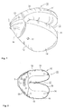
- Fig. 1 is a perspective view of an airbag according to an embodiment of the present invention, showing an inflated state
- Fig. 2 is a horizontal cross-sectional view of the airbag
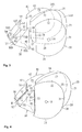
- Fig. 3 and Fig. 4 are exploded perspective views of the airbag
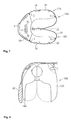
- Fig. 5 is an elevational view when viewed from the back side of an occupant 1, showing a state in which the airbag is inflated in the cabin
- Fig. 6 is a plan view of the same state.
- An airbag 10 includes a right airbag section 12 to be inflated at the right side ahead of the occupant, a left airbag section 14 to be inflated at the left side ahead of the occupant, and a rear chamber 16 communicating the base end of the right airbag section 12 and the left airbag section 14.
- the airbag 10 is for protecting the occupant sitting on the passenger's seat of a car with a right-hand steering wheel (front left seat), and the airbag apparatus is installed in an instrument panel.
- the left airbag section 14 which corresponds to the door-side airbag, is adapted to have a larger capacity and the lateral width when inflated in comparison with the right airbag section 12, which corresponds to the center-side bag.
- the capacity of the left airbag section 14 is preferably about 110-150% of the right airbag section 12.
- an bridge member such as a tie panel does not exist between the tip portions of the right airbag section 12 and the left airbag section 14, and a space 13 formed between the tip portions of the both bags 12, 14 is opened toward the occupant (that is, rightward in Fig. 1 and Fig. 2).
- the distance between the extremity of the right airbag section 12 and the extremity of the left airbag section 14 is preferably 150-350 mm, more specifically, between 170-330 mm.
- Vent holes 18 are formed on the outer surfaces of the right airbag section 12 and the left airbag section 14.
- the airbag 10 includes four panels in total, comprising an inside panel 20, a right outside panel 30, a left outside panel 40 and a base end panel 50.
- the inside panel 20 is an elongated panel of a substantially gourd shape, and is folded into two parts at the center to form a right side portion 20R and a left side portion 20L.
- the right side 20R defines the inner side surface of the right airbag section 12
- the left side 20L defines the inner side surface of the left airbag section 14.
- the inside panel 20 has the edge portions along the entire circumference formed as a lower edge 28, a tip edge 21, an upper edge 22 of the right side 20R; an upper edge 23 in the vicinity of the folded portion defining the deepest portion of the recess of the airbag; an upper edge 24, a tip edge 25, and a lower edge 26 of the left side 20L; and a lower edge 27 in the vicinity of the folded portion.
- the right outside panel 30 and the left outside panel 40 include the edge portions along the entire peripheries formed as tip edges 31 and 41, upper edges 32 and 42, straight rear edges 33 and 43, and lower edges 34 and 44.
- the vertical widths of the left side 20L and the left outside panel 40 are larger than the vertical widths of the right side 20R and the right outside panel 30, whereby the capacity of the left airbag section 14 is larger than the right airbag section 12 when inflated.
- the width laterally of the vehicle body of the left airbag section 14 is larger than that of the right airbag section 12 when inflated.
- a base end panel 50 includes a right side surfaced 50A, a base surface 50B, a left side surface 50C, a right flap 50D which constitutes the upper right side, and a left flap 50E constituting the upper left side.
- the base end panel 50 is folded so that the side surfaces 50A and 50C are formed into a substantially triangular shape, and the surface facing toward the tip side of the airbag is opened.
- the entire peripheral edge of the base end panel includes opposed edges 51, 52 of the substantially rectangular flaps 50D and 50E, front edges (the flap front edges) 53, 54 of the flaps 50D, 50E, rear edges 55, 56 of the flaps 50D, 50E, a rear edge 57 opposing the rear edges 55, 56, front edges 58, 59 of the side surfaces 50A, 50C (the side front edges), and a bottom front edge 60 connecting the side front edges 58, 59.
- the base end panel 50 When manufacturing the airbag 10, the base end panel 50 is deployed flatly, and then the rear edge 33 of the right outside panel 30 is sewed up with the side front edge 58, and the rear edge 43 of the left outside panel 40 is sewed up with the side front edge 59, respectively. Subsequently, the opposed edges 51, 52 of the flaps 50D, 50E of the base end panel 50 are sewed up with each other. Accordingly, the panels 30, 40, 50 are formed into a state shown in Fig. 4. Reference sign S in Fig. 4 shows the seam of the stitching.
- the right outside panel 30 and the right side 20R of the inside panel 20 are opposed to each other, then, the tip edges 21 and 31, the upper edges 22 and 32, the lower edges 28 and 34 are sewed up respectively.
- the left outside panel 40 and the left side 20L of the inside panel 20 are opposed to each other, and then the tip edges 25 and 41, the upper edges 24 and 42, and the lower edges 26 and 44 are sewed up respectively.
- the flap front edges 53, 54 of the base end panel 50 are sewed up with the upper edge 23 in the vicinity of the folded portion of the inside panel 20, and the bottom front edge 60 of the base end panel 50 is sewed up with the portion in the vicinity of the lower edge 27 in the vicinity of the folded portion.
- the inversed state of the airbag 10 that is, a state in which seam allowances are exposed on the front side of the airbag.
- the flap rear edges 55, 56 of the base end panel 50 and the rear edge 57 are not sewed up yet. In this state, an opening M is defined.
- the airbag is turned to be inside out through the opening M. Subsequently, by sewing up the opening M, the airbag 10 in Fig. 1 is obtained.
- the bottom surface of the base end panel 50 has two slits 70, 70 extending substantially in parallel with each other, and an inflator 71 is passed through these slits 70, 70.
- the airbag 10 is attached to the passenger airbag apparatus for protecting an occupant on the passenger's seat of a motor vehicle upon collision of the vehicle.
- the airbag 10 is folded and stored in a case (container) and the airbag apparatus is configured by attaching a lid to the case so as to cover the folded body of the airbag 10.
- the lid is adapted to be torn and opened by a pressing force applied from the airbag 10 when the airbag 10 is inflated.
- the airbag apparatus is installed in an opening for installing the airbag apparatus provided on the upper surface of the instrument panel in front of the passenger's seat in the motor vehicle.
- the inflator 71 is activated and injects gas upon collision of the vehicle.
- the gas from the inflator 71 inflates the rear chamber 16 first, and then is flown into the right airbag section 12 and the left airbag section 14 to inflate the same.
- the rear chamber 16 inflated first comes into contact with the instrument panel and the posture thereof is stabilized. Therefore, the right airbag section 12 and the left airbag section 14 are stabilized in posture not only when inflation is completed, but also during inflation.
- the space 13 like a recessed shape is defined between the tip portions of the right airbag section 12 and the left airbag section 14, and the space 13 is opened toward the occupant.
- the inflated right airbag section 12 receives the right chest of the occupant, and the inflated left airbag section 14 receives the left chest.
- the portion in the vicinity of the breast bones opposes to the space 13. Therefore, the reaction force exerted to the portion near the breast bones upon reception of the airbag is small.
- the left airbag section 14 is inflated to a large extent so as to be larger than the right airbag section 12 in width, even when a large space exists between an A-pillar 80 and a left door 82, respectively, and the occupant, as shown in Figs. 5 and 6, the left airbag section 14 is inflated so as to fill up this space, and hence the occupant is maintained sufficiently away from the A-pillar 80 and a windshield or the door in the vicinity thereof, and hence an impact to be applied to the occupant is sufficiently absorbed.
- the airbag 10 is preferably for applying a large vehicle having a large width.
- the right airbag section 12A has a large capacity having a larger lateral width than the left airbag section 14A.
- Other parts of the structure are the same as in the aforementioned embodiment.
- the airbag 10A in Figs. 7, 8 is superior in shock absorbing property by the right airbag section 12A, which corresponds to the center-side airbag.
- the left airbag section 14A has a smaller capacity having a small width than the right airbag section 12A, but has a sufficient capacity for filling up the space between the left A-pillar, the wind shield, and the left door 82, respectively, and the occupant.
- a mechanism for distributing gas from the inflator according to the capacity of the bag is preferably provided.
- Fig. 9 shows that respective bags 12B, 14B are partitioned from the rear chamber 16 by a partitioning panel 90 as the gas distributing mechanism, and holes 92, 94 for allowing gas to flow are provided on the partitioning panel 90.
- the hole 92 has a larger area in opening than the hole 94.
- Other parts of the structure of an airbag 10B in Fig. 9 are the same as the airbag 10A.
- Gas in the rear chamber 16 is supplied into the right airbag section 12B via the hole 92, and is supplied into the left airbag section 14B via the hole 94. Since the capacity of the right airbag section 12B is larger, the hole 92 has the larger diameter than the hole 94. Accordingly, more gas is supplied to the right airbag section 12B than to the left airbag section 14B, so that the respective bags 12B, 14B are inflated substantially uniformly.
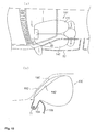
- the upper front surface of the left airbag section 14C is lower than the upper front surface of the right airbag section 12C. Accordingly, the inflated left airbag section 14C can hardly interfere with the A-pillar 80, and the posture of the inflated airbag 10C is stabilized.
- Fig. 10(a) shows a perspective plan view of a vehicle provided with the airbag
- Fig. 10(b) is a pattern diagram in cross section of the airbag
- Fig. 10(b) shows a cross section 12C' taken along the line B-B and a cross section 14C' taken along the line C-C in Fig. 10(a), shown in an overlapped state.
- Reference numeral 100 designates an instrument panel
- reference numeral 102 designates a wind shield
- reference numeral 104 designates a container of the airbag apparatus.
- a protruded portion 14d is provided at the upper rear portion of a left airbag section 14D so as to protrude rearward than the upper rear portion of a right airbag section 12D. Accordingly, the upper portion of the left airbag section 14D is larger in length in the fore-and-aft direction than that of the right airbag section 12D.
- Fig. 11(a) is a side view of the airbag 10D viewed from the right side of the vehicle body
- Fig. 11(b) is a perspective view of the inflated airbag 10D when viewed from the right rear thereof.
- a protruded portion 14e is provided on the lower rear portion of a left airbag section 14E, so that the length in the fore-and-aft direction of the lower portion of the left airbag section 14E is larger than that of the lower portion of a right airbag section 12E.
- an impact to the left chest or the belly of the occupant can be absorbed sufficiently.
- the fore-and-aft length of a left airbag section 14F is elongated as a whole, for example, by 10-100 mm, more preferably, by 40-90 mm, than a right airbag section 12F.
- the occupant can be kept sufficiently away from the A-pillar 80 or the window shield or the door in the vicinity thereof to absorb the impact sufficiently.
- the inside panel may include two or more panels joined, such as by sewing up with respect to each other.
- the inside panel may be formed of three panels including two panels having the same shape as the outside panel, and another panel connecting them with respect to each other.
- the respective airbags may be configured by methods other than those described above.
Landscapes
- Engineering & Computer Science (AREA)
- Mechanical Engineering (AREA)
- Air Bags (AREA)
Abstract
Description
Claims (9)
- An airbag the tip portion of which is inflated in a direction away from the base end by emitted gas from an inflator (71) disposed at the base end, the airbag (10; 10A-F) comprising:wherein the left airbag section (14; 14A-F) and the right airbag section (12; 12A-F) are different in capacity.a left airbag section (14; 14A-F) to be inflated at the left side ahead of an occupant (1); anda right airbag section (12; 12A-F) to be inflated at the right side ahead of the occupant (1),
- An airbag the tip portion of which is inflated in a direction away from the base end by emitted gas from an inflator (71) disposed at the base end, the airbag (10C) comprising:wherein one of the left airbag section (14C) and the right airbag section (12C), which is to be inflated along an A-pillar extends farther backward at the outer side surface of the front surface in comparison with the other one.a left airbag section (14C) to be inflated at the left side ahead of an occupant (1); anda right airbag section (12C) to be inflated at the right side ahead of the occupant (1),
- An airbag the tip portion of which is inflated in a direction away from the base end toward the rear by emitted gas from an inflator (71) disposed at the base end, the airbag (10F) comprising:wherein the length of the inflated left airbag section (14F) and of the right airbag section (12F) in the fore-and-aft direction are different from each other.a left airbag section (14F) to be inflated at the left side ahead of an occupant (1); anda right airbag section (12F) to be inflated at the right side ahead of the occupant (1),
- An airbag the tip portion of which is inflated in a direction away from the base end toward the rear by emitted gas from an inflator (71) disposed at the base end, the airbag (10D) comprising:wherein one of the upper rear portions of the inflated left (14D) and right (12D) airbag sections is protruded toward the rear with respect to the other one.a left airbag section (14D) to be inflated at the left side ahead of an occupant (1); anda right airbag section (12D) to be inflated at the right side ahead of the occupant (1),
- An airbag the tip portion of which is inflated in a direction away from the base end toward the rear by emitted gas from an inflator (71) disposed at the base end, the airbag (10E) comprising:wherein one of the lower rear portions (14e) of the inflated left (14E) and right (12E) airbag sections is protruded rearward with respect to the other one.a left airbag section (14E) to be inflated at the left side ahead of an occupant (1); anda right airbag section (12E) to be inflated at the right side ahead of the occupant (1),
- An airbag apparatus comprising the airbag according to any one of Claim 1 to Claim 5, and the inflator (71) for inflating the airbag (10A-10F).
- An airbag apparatus according to Claim 6, wherein the airbag (10B) is the airbag according to Claim 1, and distributing means (90) for supplying a greater amount of gas from the inflator to one of the left airbag section (14B) and the right airbag section (12B) having the larger capacity in comparison with the other one is provided.
- An airbag apparatus according to Claim 7, wherein the distributing means comprises a partitioning panel (90) having at least one first hole (94) allowing emitted gas from the inflator (71) to flow to the left airbag section (14B) and at least one second hole (92) allowing emitted gas from the inflator (71) to flow to the left airbag section (12B), wherein an overall opening of the at least one first hole (94) or an overall opening of the at least one second hole (92) through which the greater amount of gas is supplied is greater than the overall opening of the other.
- A vehicle comprising the airbag apparatus according to any one of Claims 6-8.
Applications Claiming Priority (2)
| Application Number | Priority Date | Filing Date | Title |
|---|---|---|---|
| JP2003394126 | 2003-11-25 | ||
| JP2003394126A JP4400188B2 (en) | 2003-11-25 | 2003-11-25 | Air bag, air bag device and vehicle |
Publications (2)
| Publication Number | Publication Date |
|---|---|
| EP1535808A1 true EP1535808A1 (en) | 2005-06-01 |
| EP1535808B1 EP1535808B1 (en) | 2008-05-28 |
Family
ID=34463776
Family Applications (1)
| Application Number | Title | Priority Date | Filing Date |
|---|---|---|---|
| EP04027774A Expired - Lifetime EP1535808B1 (en) | 2003-11-25 | 2004-11-23 | Airbag, airbag apparatus, and vehicle |
Country Status (5)
| Country | Link |
|---|---|
| US (1) | US7364188B2 (en) |
| EP (1) | EP1535808B1 (en) |
| JP (1) | JP4400188B2 (en) |
| CN (1) | CN100450835C (en) |
| DE (1) | DE602004014088D1 (en) |
Families Citing this family (45)
| Publication number | Priority date | Publication date | Assignee | Title |
|---|---|---|---|---|
| US7255367B2 (en) * | 2005-02-18 | 2007-08-14 | Tk Holdings Inc. | Air bag |
| JP4622691B2 (en) * | 2005-06-14 | 2011-02-02 | タカタ株式会社 | Air bag, manufacturing method thereof, air bag apparatus and vehicle |
| JP2007022417A (en) * | 2005-07-20 | 2007-02-01 | Mazda Motor Corp | Passenger protection device for passenger seat of vehicle |
| JP2007022416A (en) * | 2005-07-20 | 2007-02-01 | Mazda Motor Corp | Passenger protection device for passenger seat of vehicle |
| JP4347281B2 (en) | 2005-08-29 | 2009-10-21 | トヨタ自動車株式会社 | Passenger airbag |
| US7931299B2 (en) * | 2005-09-21 | 2011-04-26 | Tk Holdings, Inc. | Low risk deployment airbag cushion |
| JP5474275B2 (en) * | 2005-09-21 | 2014-04-16 | ティーケー ホールディングス,インコーポレーテッド | Passive airbag degassing |
| US20070085316A1 (en) * | 2005-10-14 | 2007-04-19 | Tk Holdings, Inc. | Airbag folding method and folded airbag produced thereby |
| US7625008B2 (en) * | 2005-10-17 | 2009-12-01 | Key Safety Systems, Inc. | Air bag with groove or recess, open or partially covered |
| US7152880B1 (en) | 2005-10-17 | 2006-12-26 | Key Safety Systems, Inc. | Grooved air bag |
| JP4123270B2 (en) * | 2005-11-24 | 2008-07-23 | トヨタ自動車株式会社 | Airbag device |
| US7484757B2 (en) * | 2005-12-08 | 2009-02-03 | Gm Global Technology Operations, Inc. | Air bag with a supported channel |
| JP4165559B2 (en) * | 2005-12-16 | 2008-10-15 | トヨタ自動車株式会社 | Airbag device |
| US20070200329A1 (en) * | 2006-02-27 | 2007-08-30 | Key Safety Systems, Inc. | Woven air bag with integrally woven 3-D tethers |
| JP4743014B2 (en) * | 2006-06-21 | 2011-08-10 | 豊田合成株式会社 | Passenger airbag |
| JP5076408B2 (en) * | 2006-09-05 | 2012-11-21 | タカタ株式会社 | Air bag, air bag device and vehicle |
| US7878537B2 (en) * | 2006-09-20 | 2011-02-01 | Tk Holdings Inc. | Airbag cushion |
| US7988194B2 (en) * | 2006-09-20 | 2011-08-02 | Tk Holdings Inc. | Airbag apparatus |
| KR101453417B1 (en) * | 2007-04-20 | 2014-10-21 | 아우토리브 디벨롭먼트 아베 | Airbag |
| JP5135938B2 (en) * | 2007-07-31 | 2013-02-06 | タカタ株式会社 | Air bag and air bag device |
| JP2009040206A (en) * | 2007-08-08 | 2009-02-26 | Takata Corp | Airbag and airbag device |
| US7862073B2 (en) | 2008-06-05 | 2011-01-04 | Gm Global Technology Operations, Inc. | Split top air bag assembly |
| JP4626681B2 (en) * | 2008-07-03 | 2011-02-09 | トヨタ自動車株式会社 | Airbag device |
| US8596678B2 (en) * | 2009-10-05 | 2013-12-03 | Autoliv Asp, Inc. | Air bag with pressure-managed gas delivery inflatable duct |
| JP5930633B2 (en) * | 2011-09-01 | 2016-06-08 | タカタ株式会社 | Air bag, air bag device and vehicle |
| JP5465117B2 (en) * | 2010-07-13 | 2014-04-09 | タカタ株式会社 | Airbag device |
| KR101219694B1 (en) * | 2010-08-30 | 2013-01-18 | 현대자동차주식회사 | Airbag apparatus for vehicle |
| US8657334B2 (en) | 2011-02-11 | 2014-02-25 | Key Safety Systems, Inc. | Airbag cushion |
| US8944462B2 (en) * | 2011-04-15 | 2015-02-03 | Trw Vehicle Safety Systems Inc. | Air bag with uninflated pocket |
| DE102012018450B4 (en) * | 2012-09-18 | 2015-02-12 | Autoliv Development Ab | Passenger car with a vehicle roof on the supporting gas bag of a passenger front airbag module and gas bag for such a passenger car |
| JP5765314B2 (en) | 2012-09-28 | 2015-08-19 | トヨタ自動車株式会社 | Airbag device for passenger seat |
| WO2015020052A1 (en) * | 2013-08-06 | 2015-02-12 | オートリブ ディベロップメント エービー | Side airbag device for vehicles |
| JP6135446B2 (en) * | 2013-10-16 | 2017-05-31 | トヨタ自動車株式会社 | Airbag device for passenger seat |
| US9376084B2 (en) | 2013-12-07 | 2016-06-28 | Autoliv Asp, Inc. | Multi-chamber airbags |
| US9580039B2 (en) * | 2014-04-22 | 2017-02-28 | Autoliv Asp, Inc. | Multi-chamber airbag with unidirectional vent |
| JP6197756B2 (en) * | 2014-07-07 | 2017-09-20 | トヨタ自動車株式会社 | Airbag device for vehicle |
| US9272684B1 (en) | 2014-10-10 | 2016-03-01 | Autoliv Asp, Inc. | Multi-chamber airbag with pinch valve |
| US9533652B1 (en) | 2015-07-14 | 2017-01-03 | Autoliv Asp, Inc. | One-directional valve for multi-chamber airbags |
| US9789844B2 (en) | 2015-11-02 | 2017-10-17 | Ford Global Technologies, Llc | Dual chamber airbag with asymmetrically tunable parameters and method of manufacturing the same |
| JP6390596B2 (en) * | 2015-11-18 | 2018-09-19 | トヨタ自動車株式会社 | Airbag device |
| US10427638B2 (en) | 2016-06-08 | 2019-10-01 | Autoliv Asp, Inc. | Frontal airbag assemblies for reducing rotational velocity of a head of an occupant |
| US9969346B2 (en) * | 2016-08-24 | 2018-05-15 | Ford Global Technologies, Llc | Airbag restraint system |
| US10293777B2 (en) | 2016-08-26 | 2019-05-21 | Autoliv Asp, Inc. | Multi-cushion airbag assemblies for reducing rotational velocity of an occupant's head |
| US10293775B2 (en) | 2016-10-21 | 2019-05-21 | Autoliv Asp, Inc. | Frontal airbag assemblies for reducing rotational velocity of a head of an occupant |
| US11027688B2 (en) | 2019-08-27 | 2021-06-08 | Autoliv Asp, Inc. | Systems and methods to support an inflatable airbag cushion |
Citations (6)
| Publication number | Priority date | Publication date | Assignee | Title |
|---|---|---|---|---|
| JPH0332956A (en) * | 1989-06-30 | 1991-02-13 | Mazda Motor Corp | Air bag device for automobile |
| US5324070A (en) * | 1992-01-31 | 1994-06-28 | Takata Corporation | Air bag device for a knee of an occupant |
| WO1996005986A1 (en) * | 1994-08-25 | 1996-02-29 | Johann Berger | Method of manufacturing an airbag hollow body |
| US20020041090A1 (en) * | 1999-05-21 | 2002-04-11 | Thomas Wohllebe | Airbag system for a motor vehicle |
| US20020105179A1 (en) * | 2001-02-07 | 2002-08-08 | Trw Automotive Safety Systems Gmbh & Co. Kg | Gas bag module |
| EP1300300A1 (en) * | 2000-07-07 | 2003-04-09 | Toyoda Gosei Co., Ltd. | Air bag device for knee protection |
Family Cites Families (19)
| Publication number | Priority date | Publication date | Assignee | Title |
|---|---|---|---|---|
| JPS512354Y2 (en) | 1971-04-30 | 1976-01-23 | ||
| JPS4923176A (en) | 1972-06-26 | 1974-03-01 | ||
| US4262931A (en) * | 1979-09-18 | 1981-04-21 | Ford Motor Company | Air bag restraint system |
| JPH0456655A (en) * | 1990-06-27 | 1992-02-24 | Takata Kk | Air bag |
| JPH04292239A (en) | 1991-03-20 | 1992-10-16 | Asahi Chem Ind Co Ltd | Air bag for vehicle |
| US5129675A (en) * | 1991-05-02 | 1992-07-14 | General Motors Corporation | Occupant restraint cushion |
| WO1993016902A1 (en) * | 1992-02-21 | 1993-09-02 | Irvin Great Britain Limited | Impact protection arrangements for the occupant(s) of a motor vehicle |
| US6003896A (en) * | 1996-03-15 | 1999-12-21 | Autoliv Asp, Inc. | Airbag cushion having irregular configuration |
| DE19707997C2 (en) * | 1997-02-27 | 2000-10-26 | Hs Tech & Design | Passenger airbag device |
| JP3760424B2 (en) | 1996-08-30 | 2006-03-29 | 本田技研工業株式会社 | Airbag device for vehicle |
| JP3035691U (en) * | 1996-09-12 | 1997-03-28 | 桂司 古川 | Air bag for automobile |
| DE29700804U1 (en) * | 1997-01-17 | 1997-04-10 | Gercken Karl Dipl Ing | Airbags for motor vehicles, in particular cars |
| DE29702441U1 (en) * | 1997-02-12 | 1997-06-12 | Trw Occupant Restraint Systems Gmbh, 73551 Alfdorf | Driver-side occupant restraint system |
| DE19933586C1 (en) * | 1999-07-17 | 2001-01-11 | Autoliv Dev | Two-person airbag device for automobile passenger restraint has airbag sack divided into 2 chambers coupled via flow path by sewn seam extending in curve between one longitudinal edge and sack center point |
| US7182365B2 (en) * | 2000-07-07 | 2007-02-27 | Toyoda Gosei Co., Ltd. | Air bag device for knee protection |
| DE60124550T2 (en) * | 2000-07-07 | 2007-07-05 | Toyoda Gosei Co., Ltd. | AIR BAG FOR KNEE PROTECTION |
| DE20022020U1 (en) * | 2000-12-28 | 2001-11-08 | Trw Automotive Safety Sys Gmbh | Airbag module |
| DE20109596U1 (en) * | 2001-06-08 | 2001-10-18 | Trw Automotive Safety Sys Gmbh | Airbag for a vehicle occupant restraint system |
| DE10224138A1 (en) * | 2002-05-24 | 2003-12-11 | Takata Petri Ag | Driver or front passenger airbag |
-
2003
- 2003-11-25 JP JP2003394126A patent/JP4400188B2/en not_active Expired - Fee Related
-
2004
- 2004-10-27 US US10/974,178 patent/US7364188B2/en not_active Expired - Fee Related
- 2004-11-09 CN CNB2004100923573A patent/CN100450835C/en not_active Expired - Fee Related
- 2004-11-23 DE DE602004014088T patent/DE602004014088D1/en not_active Expired - Lifetime
- 2004-11-23 EP EP04027774A patent/EP1535808B1/en not_active Expired - Lifetime
Patent Citations (6)
| Publication number | Priority date | Publication date | Assignee | Title |
|---|---|---|---|---|
| JPH0332956A (en) * | 1989-06-30 | 1991-02-13 | Mazda Motor Corp | Air bag device for automobile |
| US5324070A (en) * | 1992-01-31 | 1994-06-28 | Takata Corporation | Air bag device for a knee of an occupant |
| WO1996005986A1 (en) * | 1994-08-25 | 1996-02-29 | Johann Berger | Method of manufacturing an airbag hollow body |
| US20020041090A1 (en) * | 1999-05-21 | 2002-04-11 | Thomas Wohllebe | Airbag system for a motor vehicle |
| EP1300300A1 (en) * | 2000-07-07 | 2003-04-09 | Toyoda Gosei Co., Ltd. | Air bag device for knee protection |
| US20020105179A1 (en) * | 2001-02-07 | 2002-08-08 | Trw Automotive Safety Systems Gmbh & Co. Kg | Gas bag module |
Non-Patent Citations (1)
| Title |
|---|
| PATENT ABSTRACTS OF JAPAN vol. 015, no. 168 (M - 1107) 26 April 1991 (1991-04-26) * |
Also Published As
| Publication number | Publication date |
|---|---|
| US7364188B2 (en) | 2008-04-29 |
| JP2005153668A (en) | 2005-06-16 |
| JP4400188B2 (en) | 2010-01-20 |
| US20050110249A1 (en) | 2005-05-26 |
| CN100450835C (en) | 2009-01-14 |
| CN1621281A (en) | 2005-06-01 |
| DE602004014088D1 (en) | 2008-07-10 |
| EP1535808B1 (en) | 2008-05-28 |
Similar Documents
| Publication | Publication Date | Title |
|---|---|---|
| EP1535808B1 (en) | Airbag, airbag apparatus, and vehicle | |
| US7695012B2 (en) | Airbag systems with a split pocket | |
| US10427638B2 (en) | Frontal airbag assemblies for reducing rotational velocity of a head of an occupant | |
| US9487180B2 (en) | Vehicular curtain air-bag device, and mounting structure for same | |
| USRE43353E1 (en) | Divided airbag system | |
| JP5853615B2 (en) | Upper body structure of the vehicle | |
| US8011690B2 (en) | Trim panel breakaway feature | |
| EP1364839A2 (en) | Improved curtain air bag assembly | |
| CN107757543A (en) | The seat of side air bag device is installed | |
| US20080290634A1 (en) | Curtain side-airbag device | |
| CN100425479C (en) | Housing for an airbag device | |
| JP4175338B2 (en) | Airbag device | |
| US7000945B2 (en) | Inflatable windshield curtain | |
| US7461862B2 (en) | Airbag and airbag system | |
| KR100521863B1 (en) | Window air bag system and method of mounting the same | |
| US7390020B2 (en) | Airbag and airbag apparatus | |
| US6659502B2 (en) | Impact protection device and method of providing an impact protection | |
| JP2001080446A (en) | Head protection airbag | |
| EP1533197A1 (en) | Side airbag and method of folding | |
| EP3848253B1 (en) | Side airbag device | |
| JP2018114838A (en) | Airbag | |
| JP2004244006A (en) | Airbag, airbag device, and vehicle | |
| US11718261B2 (en) | Vehicle passenger protection system comprising an airbag module | |
| JP4570729B2 (en) | Arrangement structure of head protection airbag device | |
| US7367586B2 (en) | Airbag restraint for automotive vehicle |
Legal Events
| Date | Code | Title | Description |
|---|---|---|---|
| PUAI | Public reference made under article 153(3) epc to a published international application that has entered the european phase |
Free format text: ORIGINAL CODE: 0009012 |
|
| AK | Designated contracting states |
Kind code of ref document: A1 Designated state(s): AT BE BG CH CY CZ DE DK EE ES FI FR GB GR HU IE IS IT LI LU MC NL PL PT RO SE SI SK TR |
|
| AX | Request for extension of the european patent |
Extension state: AL HR LT LV MK YU |
|
| 17P | Request for examination filed |
Effective date: 20051103 |
|
| AKX | Designation fees paid |
Designated state(s): DE FR GB SE |
|
| 17Q | First examination report despatched |
Effective date: 20060512 |
|
| 17Q | First examination report despatched |
Effective date: 20060512 |
|
| GRAP | Despatch of communication of intention to grant a patent |
Free format text: ORIGINAL CODE: EPIDOSNIGR1 |
|
| GRAS | Grant fee paid |
Free format text: ORIGINAL CODE: EPIDOSNIGR3 |
|
| GRAA | (expected) grant |
Free format text: ORIGINAL CODE: 0009210 |
|
| AK | Designated contracting states |
Kind code of ref document: B1 Designated state(s): DE FR GB SE |
|
| REG | Reference to a national code |
Ref country code: GB Ref legal event code: FG4D |
|
| REF | Corresponds to: |
Ref document number: 602004014088 Country of ref document: DE Date of ref document: 20080710 Kind code of ref document: P |
|
| PG25 | Lapsed in a contracting state [announced via postgrant information from national office to epo] |
Ref country code: SE Free format text: LAPSE BECAUSE OF FAILURE TO SUBMIT A TRANSLATION OF THE DESCRIPTION OR TO PAY THE FEE WITHIN THE PRESCRIBED TIME-LIMIT Effective date: 20080828 |
|
| PLBE | No opposition filed within time limit |
Free format text: ORIGINAL CODE: 0009261 |
|
| STAA | Information on the status of an ep patent application or granted ep patent |
Free format text: STATUS: NO OPPOSITION FILED WITHIN TIME LIMIT |
|
| 26N | No opposition filed |
Effective date: 20090303 |
|
| REG | Reference to a national code |
Ref country code: FR Ref legal event code: ST Effective date: 20090731 |
|
| PG25 | Lapsed in a contracting state [announced via postgrant information from national office to epo] |
Ref country code: FR Free format text: LAPSE BECAUSE OF NON-PAYMENT OF DUE FEES Effective date: 20081130 |
|
| PGFP | Annual fee paid to national office [announced via postgrant information from national office to epo] |
Ref country code: GB Payment date: 20131120 Year of fee payment: 10 |
|
| GBPC | Gb: european patent ceased through non-payment of renewal fee |
Effective date: 20141123 |
|
| PG25 | Lapsed in a contracting state [announced via postgrant information from national office to epo] |
Ref country code: GB Free format text: LAPSE BECAUSE OF NON-PAYMENT OF DUE FEES Effective date: 20141123 |
|
| REG | Reference to a national code |
Ref country code: DE Ref legal event code: R082 Ref document number: 602004014088 Country of ref document: DE Representative=s name: KRAUS & WEISERT PATENTANWAELTE PARTGMBB, DE Ref country code: DE Ref legal event code: R081 Ref document number: 602004014088 Country of ref document: DE Owner name: JOYSON SAFETY SYSTEMS JAPAN K.K., JP Free format text: FORMER OWNER: TAKATA CORP., TOKIO/TOKYO, JP |
|
| PGFP | Annual fee paid to national office [announced via postgrant information from national office to epo] |
Ref country code: DE Payment date: 20181120 Year of fee payment: 15 |
|
| REG | Reference to a national code |
Ref country code: DE Ref legal event code: R119 Ref document number: 602004014088 Country of ref document: DE |
|
| PG25 | Lapsed in a contracting state [announced via postgrant information from national office to epo] |
Ref country code: DE Free format text: LAPSE BECAUSE OF NON-PAYMENT OF DUE FEES Effective date: 20200603 |