EP1535716A1 - Vorrichtung und Verfahren zur Herstellung von Blasfolien - Google Patents
Vorrichtung und Verfahren zur Herstellung von Blasfolien Download PDFInfo
- Publication number
- EP1535716A1 EP1535716A1 EP04027401A EP04027401A EP1535716A1 EP 1535716 A1 EP1535716 A1 EP 1535716A1 EP 04027401 A EP04027401 A EP 04027401A EP 04027401 A EP04027401 A EP 04027401A EP 1535716 A1 EP1535716 A1 EP 1535716A1
- Authority
- EP
- European Patent Office
- Prior art keywords
- nozzle
- film
- suction device
- flattening
- film tube
- Prior art date
- Legal status (The legal status is an assumption and is not a legal conclusion. Google has not performed a legal analysis and makes no representation as to the accuracy of the status listed.)
- Withdrawn
Links
- 238000004519 manufacturing process Methods 0.000 title claims abstract description 12
- 238000000034 method Methods 0.000 title claims description 6
- 238000001816 cooling Methods 0.000 claims abstract description 30
- 238000010943 off-gassing Methods 0.000 description 14
- 239000004033 plastic Substances 0.000 description 11
- 229920003023 plastic Polymers 0.000 description 11
- 241000196324 Embryophyta Species 0.000 description 8
- 239000011888 foil Substances 0.000 description 5
- -1 Vapors Substances 0.000 description 4
- 238000009833 condensation Methods 0.000 description 3
- 230000005494 condensation Effects 0.000 description 3
- 238000001125 extrusion Methods 0.000 description 3
- 210000000554 iris Anatomy 0.000 description 3
- 239000000654 additive Substances 0.000 description 2
- 239000000443 aerosol Substances 0.000 description 2
- 238000010276 construction Methods 0.000 description 2
- 239000007857 degradation product Substances 0.000 description 2
- 239000007789 gas Substances 0.000 description 2
- 238000003197 gene knockdown Methods 0.000 description 2
- 239000000178 monomer Substances 0.000 description 2
- 239000002245 particle Substances 0.000 description 2
- 230000032258 transport Effects 0.000 description 2
- 240000004752 Laburnum anagyroides Species 0.000 description 1
- 239000004952 Polyamide Substances 0.000 description 1
- 239000004698 Polyethylene Substances 0.000 description 1
- 230000006978 adaptation Effects 0.000 description 1
- 238000004140 cleaning Methods 0.000 description 1
- 230000001419 dependent effect Effects 0.000 description 1
- 230000000694 effects Effects 0.000 description 1
- 210000003128 head Anatomy 0.000 description 1
- 230000001771 impaired effect Effects 0.000 description 1
- 238000003780 insertion Methods 0.000 description 1
- 230000037431 insertion Effects 0.000 description 1
- 238000009434 installation Methods 0.000 description 1
- 238000012423 maintenance Methods 0.000 description 1
- 239000000203 mixture Substances 0.000 description 1
- 239000012785 packaging film Substances 0.000 description 1
- 229920006280 packaging film Polymers 0.000 description 1
- 238000004806 packaging method and process Methods 0.000 description 1
- 229920002647 polyamide Polymers 0.000 description 1
- 229920000573 polyethylene Polymers 0.000 description 1
- 229920000098 polyolefin Polymers 0.000 description 1
- 238000001556 precipitation Methods 0.000 description 1
- 230000000630 rising effect Effects 0.000 description 1
- 239000002904 solvent Substances 0.000 description 1
Images
Classifications
-
- B—PERFORMING OPERATIONS; TRANSPORTING
- B29—WORKING OF PLASTICS; WORKING OF SUBSTANCES IN A PLASTIC STATE IN GENERAL
- B29C—SHAPING OR JOINING OF PLASTICS; SHAPING OF MATERIAL IN A PLASTIC STATE, NOT OTHERWISE PROVIDED FOR; AFTER-TREATMENT OF THE SHAPED PRODUCTS, e.g. REPAIRING
- B29C48/00—Extrusion moulding, i.e. expressing the moulding material through a die or nozzle which imparts the desired form; Apparatus therefor
- B29C48/25—Component parts, details or accessories; Auxiliary operations
- B29C48/96—Safety devices
- B29C48/965—Personnel safety, e.g. safety for the operator
-
- B—PERFORMING OPERATIONS; TRANSPORTING
- B29—WORKING OF PLASTICS; WORKING OF SUBSTANCES IN A PLASTIC STATE IN GENERAL
- B29C—SHAPING OR JOINING OF PLASTICS; SHAPING OF MATERIAL IN A PLASTIC STATE, NOT OTHERWISE PROVIDED FOR; AFTER-TREATMENT OF THE SHAPED PRODUCTS, e.g. REPAIRING
- B29C48/00—Extrusion moulding, i.e. expressing the moulding material through a die or nozzle which imparts the desired form; Apparatus therefor
- B29C48/03—Extrusion moulding, i.e. expressing the moulding material through a die or nozzle which imparts the desired form; Apparatus therefor characterised by the shape of the extruded material at extrusion
- B29C48/09—Articles with cross-sections having partially or fully enclosed cavities, e.g. pipes or channels
- B29C48/10—Articles with cross-sections having partially or fully enclosed cavities, e.g. pipes or channels flexible, e.g. blown foils
-
- B—PERFORMING OPERATIONS; TRANSPORTING
- B29—WORKING OF PLASTICS; WORKING OF SUBSTANCES IN A PLASTIC STATE IN GENERAL
- B29C—SHAPING OR JOINING OF PLASTICS; SHAPING OF MATERIAL IN A PLASTIC STATE, NOT OTHERWISE PROVIDED FOR; AFTER-TREATMENT OF THE SHAPED PRODUCTS, e.g. REPAIRING
- B29C48/00—Extrusion moulding, i.e. expressing the moulding material through a die or nozzle which imparts the desired form; Apparatus therefor
- B29C48/14—Extrusion moulding, i.e. expressing the moulding material through a die or nozzle which imparts the desired form; Apparatus therefor characterised by the particular extruding conditions, e.g. in a modified atmosphere or by using vibration
- B29C48/147—Extrusion moulding, i.e. expressing the moulding material through a die or nozzle which imparts the desired form; Apparatus therefor characterised by the particular extruding conditions, e.g. in a modified atmosphere or by using vibration after the die nozzle
- B29C48/1472—Extrusion moulding, i.e. expressing the moulding material through a die or nozzle which imparts the desired form; Apparatus therefor characterised by the particular extruding conditions, e.g. in a modified atmosphere or by using vibration after the die nozzle at the die nozzle exit zone
-
- B—PERFORMING OPERATIONS; TRANSPORTING
- B29—WORKING OF PLASTICS; WORKING OF SUBSTANCES IN A PLASTIC STATE IN GENERAL
- B29C—SHAPING OR JOINING OF PLASTICS; SHAPING OF MATERIAL IN A PLASTIC STATE, NOT OTHERWISE PROVIDED FOR; AFTER-TREATMENT OF THE SHAPED PRODUCTS, e.g. REPAIRING
- B29C48/00—Extrusion moulding, i.e. expressing the moulding material through a die or nozzle which imparts the desired form; Apparatus therefor
- B29C48/25—Component parts, details or accessories; Auxiliary operations
- B29C48/36—Means for plasticising or homogenising the moulding material or forcing it through the nozzle or die
- B29C48/50—Details of extruders
- B29C48/76—Venting, drying means; Degassing means
- B29C48/768—Venting, drying means; Degassing means outside the apparatus, e.g. after the die
-
- B—PERFORMING OPERATIONS; TRANSPORTING
- B29—WORKING OF PLASTICS; WORKING OF SUBSTANCES IN A PLASTIC STATE IN GENERAL
- B29C—SHAPING OR JOINING OF PLASTICS; SHAPING OF MATERIAL IN A PLASTIC STATE, NOT OTHERWISE PROVIDED FOR; AFTER-TREATMENT OF THE SHAPED PRODUCTS, e.g. REPAIRING
- B29C48/00—Extrusion moulding, i.e. expressing the moulding material through a die or nozzle which imparts the desired form; Apparatus therefor
- B29C48/25—Component parts, details or accessories; Auxiliary operations
- B29C48/88—Thermal treatment of the stream of extruded material, e.g. cooling
- B29C48/90—Thermal treatment of the stream of extruded material, e.g. cooling with calibration or sizing, i.e. combined with fixing or setting of the final dimensions of the extruded article
- B29C48/901—Thermal treatment of the stream of extruded material, e.g. cooling with calibration or sizing, i.e. combined with fixing or setting of the final dimensions of the extruded article of hollow bodies
- B29C48/903—Thermal treatment of the stream of extruded material, e.g. cooling with calibration or sizing, i.e. combined with fixing or setting of the final dimensions of the extruded article of hollow bodies externally
-
- B—PERFORMING OPERATIONS; TRANSPORTING
- B29—WORKING OF PLASTICS; WORKING OF SUBSTANCES IN A PLASTIC STATE IN GENERAL
- B29C—SHAPING OR JOINING OF PLASTICS; SHAPING OF MATERIAL IN A PLASTIC STATE, NOT OTHERWISE PROVIDED FOR; AFTER-TREATMENT OF THE SHAPED PRODUCTS, e.g. REPAIRING
- B29C2791/00—Shaping characteristics in general
- B29C2791/004—Shaping under special conditions
- B29C2791/007—Using fluid under pressure
-
- B—PERFORMING OPERATIONS; TRANSPORTING
- B29—WORKING OF PLASTICS; WORKING OF SUBSTANCES IN A PLASTIC STATE IN GENERAL
- B29C—SHAPING OR JOINING OF PLASTICS; SHAPING OF MATERIAL IN A PLASTIC STATE, NOT OTHERWISE PROVIDED FOR; AFTER-TREATMENT OF THE SHAPED PRODUCTS, e.g. REPAIRING
- B29C48/00—Extrusion moulding, i.e. expressing the moulding material through a die or nozzle which imparts the desired form; Apparatus therefor
- B29C48/001—Combinations of extrusion moulding with other shaping operations
- B29C48/0018—Combinations of extrusion moulding with other shaping operations combined with shaping by orienting, stretching or shrinking, e.g. film blowing
-
- B—PERFORMING OPERATIONS; TRANSPORTING
- B29—WORKING OF PLASTICS; WORKING OF SUBSTANCES IN A PLASTIC STATE IN GENERAL
- B29C—SHAPING OR JOINING OF PLASTICS; SHAPING OF MATERIAL IN A PLASTIC STATE, NOT OTHERWISE PROVIDED FOR; AFTER-TREATMENT OF THE SHAPED PRODUCTS, e.g. REPAIRING
- B29C48/00—Extrusion moulding, i.e. expressing the moulding material through a die or nozzle which imparts the desired form; Apparatus therefor
- B29C48/001—Combinations of extrusion moulding with other shaping operations
- B29C48/0019—Combinations of extrusion moulding with other shaping operations combined with shaping by flattening, folding or bending
-
- B—PERFORMING OPERATIONS; TRANSPORTING
- B29—WORKING OF PLASTICS; WORKING OF SUBSTANCES IN A PLASTIC STATE IN GENERAL
- B29C—SHAPING OR JOINING OF PLASTICS; SHAPING OF MATERIAL IN A PLASTIC STATE, NOT OTHERWISE PROVIDED FOR; AFTER-TREATMENT OF THE SHAPED PRODUCTS, e.g. REPAIRING
- B29C48/00—Extrusion moulding, i.e. expressing the moulding material through a die or nozzle which imparts the desired form; Apparatus therefor
- B29C48/25—Component parts, details or accessories; Auxiliary operations
- B29C48/88—Thermal treatment of the stream of extruded material, e.g. cooling
- B29C48/885—External treatment, e.g. by using air rings for cooling tubular films
-
- B—PERFORMING OPERATIONS; TRANSPORTING
- B29—WORKING OF PLASTICS; WORKING OF SUBSTANCES IN A PLASTIC STATE IN GENERAL
- B29C—SHAPING OR JOINING OF PLASTICS; SHAPING OF MATERIAL IN A PLASTIC STATE, NOT OTHERWISE PROVIDED FOR; AFTER-TREATMENT OF THE SHAPED PRODUCTS, e.g. REPAIRING
- B29C48/00—Extrusion moulding, i.e. expressing the moulding material through a die or nozzle which imparts the desired form; Apparatus therefor
- B29C48/25—Component parts, details or accessories; Auxiliary operations
- B29C48/88—Thermal treatment of the stream of extruded material, e.g. cooling
- B29C48/90—Thermal treatment of the stream of extruded material, e.g. cooling with calibration or sizing, i.e. combined with fixing or setting of the final dimensions of the extruded article
- B29C48/908—Thermal treatment of the stream of extruded material, e.g. cooling with calibration or sizing, i.e. combined with fixing or setting of the final dimensions of the extruded article characterised by calibrator surface, e.g. structure or holes for lubrication, cooling or venting
-
- B—PERFORMING OPERATIONS; TRANSPORTING
- B29—WORKING OF PLASTICS; WORKING OF SUBSTANCES IN A PLASTIC STATE IN GENERAL
- B29C—SHAPING OR JOINING OF PLASTICS; SHAPING OF MATERIAL IN A PLASTIC STATE, NOT OTHERWISE PROVIDED FOR; AFTER-TREATMENT OF THE SHAPED PRODUCTS, e.g. REPAIRING
- B29C48/00—Extrusion moulding, i.e. expressing the moulding material through a die or nozzle which imparts the desired form; Apparatus therefor
- B29C48/25—Component parts, details or accessories; Auxiliary operations
- B29C48/88—Thermal treatment of the stream of extruded material, e.g. cooling
- B29C48/911—Cooling
- B29C48/9115—Cooling of hollow articles
- B29C48/912—Cooling of hollow articles of tubular films
-
- B—PERFORMING OPERATIONS; TRANSPORTING
- B29—WORKING OF PLASTICS; WORKING OF SUBSTANCES IN A PLASTIC STATE IN GENERAL
- B29K—INDEXING SCHEME ASSOCIATED WITH SUBCLASSES B29B, B29C OR B29D, RELATING TO MOULDING MATERIALS OR TO MATERIALS FOR MOULDS, REINFORCEMENTS, FILLERS OR PREFORMED PARTS, e.g. INSERTS
- B29K2023/00—Use of polyalkenes or derivatives thereof as moulding material
- B29K2023/04—Polymers of ethylene
- B29K2023/06—PE, i.e. polyethylene
-
- B—PERFORMING OPERATIONS; TRANSPORTING
- B29—WORKING OF PLASTICS; WORKING OF SUBSTANCES IN A PLASTIC STATE IN GENERAL
- B29K—INDEXING SCHEME ASSOCIATED WITH SUBCLASSES B29B, B29C OR B29D, RELATING TO MOULDING MATERIALS OR TO MATERIALS FOR MOULDS, REINFORCEMENTS, FILLERS OR PREFORMED PARTS, e.g. INSERTS
- B29K2105/00—Condition, form or state of moulded material or of the material to be shaped
- B29K2105/25—Solid
- B29K2105/253—Preform
- B29K2105/258—Tubular
-
- B—PERFORMING OPERATIONS; TRANSPORTING
- B29—WORKING OF PLASTICS; WORKING OF SUBSTANCES IN A PLASTIC STATE IN GENERAL
- B29L—INDEXING SCHEME ASSOCIATED WITH SUBCLASS B29C, RELATING TO PARTICULAR ARTICLES
- B29L2023/00—Tubular articles
- B29L2023/001—Tubular films, sleeves
Definitions
- the invention relates to a device and a method for producing blown films.
- blown films are well known in the art.
- the principle After a hot plastic melt, which exits an extruder, through an annular Nozzle to a tubular film, possibly via a deflection substantially perpendicular extruded upwards.
- the film tube is discharged from the nozzle by air in the interior of the film tube is blown, inflated to the desired outer diameter, which, depending on the selected take-off speed, the desired Film thickness sets.
- the blown film is using a Kalibrierkorbes, which surrounds, supports and stabilizes the film tube.
- the film tube with Help of air from outside and / or inside cooled.
- the cooled film tube is then by means of a flattening device, e.g. a pair of rollers, folded into a flat film.
- the object of the present invention is an apparatus and a method for the production of blown films in which outgassing of volatile components from the plastic melt not to deposits due to condensation on components of the blown film plant to lead.
- the object is achieved by a device in which the outgassing after the exit of the Foil tube are sucked out of the nozzle using a suction device.
- the invention accordingly provides a device for producing blown films, at least consisting of an extruder, the outlet of which is connected to an annular nozzle, a flat laying device arranged above or below the nozzle and one between the Nozzle and the flattening device arranged annular cooling device, characterized in that a suction device is arranged between the nozzle and the flat laying device is.
- the suction device which according to the invention outgassing of the plastic melt volatile Components sucks, can in principle in the known from the prior art devices be integrated for the production of blown films.
- the device according to the invention comprises an extruder from which emerges a hot plastic melt during operation.
- the extruder is on its outlet connected to an annular nozzle, which the plastic melt to a Foil tube extruded.
- the extruder is arranged horizontally.
- the annular nozzle is, for example, an annular gap nozzle.
- film tube may also be extruded substantially vertically downwardly. If Unless otherwise indicated, the terms "above” and “below” refer to below a device in which the film tube is extruded upwards, wherein for a device with downward extrusion then according to the reverse construction applies.
- air is blown to the film to the desired width and depending from the selected take-off speed to the desired thickness.
- volatile components preferably occur in areas of the film tube high surface temperature, i. Outgassing is especially in areas near the nozzle to observe.
- the volatile components may be monomers, oligomers, Additives, solvents, degradation products or the like. act.
- the suction device between the nozzle, from which the plastic melt leaking, and the flattening device with which the cooled film tube folded It will be appropriated. If the film tube is extruded and ejected substantially vertically upward the flattening device withdrawn, then the suction device is located above the nozzle and below the flattening device. Is in the alternative design of the blown film plant of Foil tube, however, extruded and pulled down substantially vertically downwards, then the Saugvorrides is located below the nozzle and above the flattening device.
- the suction device is positioned so that above the suction device due to the Temperature of the film only small or negligible amounts of volatile components escape.
- the suction device is also positioned so that the upwardly rising Gases, vapors, aerosols or the like be sucked off before they attach to components of the device, such as e.g. the cooling device or possibly the calibration device, can knock down.
- the erfmdungswashe apparatus for the production of blown film (hereinafter also as blown film plant designated), as known from the prior art, between the nozzle and the flattening device on an annular cooling device.
- the cooling device is preferred arranged near the nozzle. If the film tube runs upwards, the cooling device is above the nozzle and arranged below the flattening device. With the help of the cooling device in the form of a cooling ring, cooling air over the circumference becomes uniform against the film tube blown. The upward flowing cooling air transports the outgassings upwards.
- the suction device is between the cooling device and the flattening device arranged.
- this means that the suction device is arranged above the cooling device.
- a further cooling device above the suction device i. between the suction device and the flattening device, be arranged. It can also be arranged several other cooling devices.
- Cooling devices with a variable diameter are known in the prior art. This allows the diameter of the cooling device to be adapted to the diameter of the film tube.
- the device according to the invention preferably has a calibration device between the Cooling device and the flattening device, in particular between the suction device and the flattening device.
- a calibration device is thus above the cooling device arranged.
- the suction device is accordingly in the upward leading Construction of the blown film plant preferably above the cooling device and below the Calibration.
- the calibration device serves to stabilize the film.
- calibration As known from the prior art, consist in a simple design of several strips, which are arranged to a polygon, which is the outer diameter of the Hose limited. A better effect is achieved by several such arrangements be arranged at a certain distance one above the other. Another improvement of Calibration is achieved by replacing the strips with rod-shaped elements which reduce the friction of the film tube at the calibration device.
- the film tube passes in the device according to the invention above the calibrating a flattening device.
- the flattening device may for example consist of a pair of rollers consist.
- two flat plate-shaped elements can also be used for flattening the film tube serve below a pair of rollers, which are arranged wedge-shaped to each other. These plate-shaped elements can be used, for example, as simple plates, strip gratings, roller conveyors, Sheets, perforated and / or cooled sheets to be carried out.
- the suction device which sucks out volatile components in the device according to the invention, is preferably located above the cooling device and below calibration device.
- the suction device surrounds the film tube annularly.
- the bladder may be used in any geometry, e.g. angular, oval, surrounded.
- the suction device has an opening through which the film tube passes becomes. The diameter of this opening is preferably just chosen so that the suction device the film tube is not touched or excessive friction between the suction device and the bladder is avoided.
- the opening of the suction device preferably has a variable diameter, which depends on the diameter of the film tube can be adjusted.
- the diameter of the opening there can e.g. both the lower, i.e. the nozzle facing, as well as the upper, i. the flattening device facing, limiting the annular suction device equipped with an iris diaphragm be whose diameter are independent or dependent on each other adjustable.
- the diameter of the opening may also be adjustable thereby that the suction device consists of several components, which have different sizes and are interchangeable, so that depending on the desired diameter, the components in the desired Size to be selected.
- the suction device may consist of several arcuate There are components which, when assembled, surround the film tube in an annular manner.
- the suction device can also be analogous to a cooling ring known from the prior art be executed. Such a suction device is operated so that instead of an overpressure a negative pressure is applied, sucked through the air instead of being blown.
- suction device devices may be installed, one over the circumference ensure a uniform flow of the mixture of air and outgassing to be sucked off.
- the suction device is provided with at least one hose or pipe for exhausting the outgassing Mistake.
- the suction device is preferably provided with heatable inlets and outlets, to the condensation or the precipitation of the outgassing in the supply and discharge lines to avoid.
- at the suction device is preferably a cold trap for a controlled Condensation of the outgassing provided.
- the suction device makes it possible, low molecular weight, volatile components, which from the Outgas the film tube, suck it off. This prevents the outgassing on components the blown film installation, such as the calibration, knock down. The pollution of the Blown film plant is thus reduced. In addition, no particles of condensed outgassing can fall down on the film, which is why the film quality is improved.
- Another object of the invention is a process for the production of blown films using the device according to the invention.
- films are e.g. of polyamide and polyolefins, e.g. Polyethylene, manufactured.
- the films can be single-layered or multi-layered.
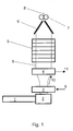
- Figure 1 shows schematically a erfmdungshacke apparatus for producing blown film.
- An extruder 1 is with a nozzle 2 connected to the exiting the extruder 1 plastic melt to a Foil tube 8 extruded.
- the film tube 8 occurs in the illustrated embodiment in Essentially vertically upward from the nozzle 2 from.
- Both functions i. the diversion of Plastic melt from the horizontal to the vertical and the extrusion of the film tube by means of an annular gap nozzle, can be integrated in a single component or in two separate components of the blown film plant.
- Both the deflection and the extrusion takes place in a single component, the blow head.
- a cooling device 3 is arranged in the form of a cooling ring. With help of the cooling ring 3 cooling air 9 is blown from the outside onto the film tube 8.
- the upstairs flowing cooling air 10 transports outgassing from the film tube 8 in the direction of the suction device 4.
- the suction device 4 sucks the outgassing 11.
- a calibration device 5 is arranged above the suction device 4.
- a flattening device consisting of a wedge-shaped arranged to each other arranged plate pair 6 and a pair of rollers 7, which largely cooled film tube 8 happens.
- the flattening device 6, 7 folds the film tube 8 to a flat film 8 'together.
Landscapes
- Engineering & Computer Science (AREA)
- Mechanical Engineering (AREA)
- Physics & Mathematics (AREA)
- Thermal Sciences (AREA)
- Shaping By String And By Release Of Stress In Plastics And The Like (AREA)
- Extrusion Moulding Of Plastics Or The Like (AREA)
Abstract
Description
Claims (7)
- Vorrichtung zur Herstellung von Blasfolien, wenigstens bestehend aus einem Extruder (1), dessen Austritt mit einer ringförmigen Düse (2) verbunden ist, einer oberhalb oder unterhalb der Düse (2) angeordneten Flachlegeeinrichtung (6, 7) und einer zwischen der Düse (2) und der Flachlegeeinrichtung (6, 7) angeordneten ringförmigen Kühleinrichtung (3), dadurch gekennzeichnet, dass eine Saugvorrichtung (4) zwischen der Düse (2) und der Flachlegeeinrichtung (6, 7) angeordnet ist.
- Vorrichtung nach Anspruch 1, dadurch gekennzeichnet, dass die Saugvorrichtung (4) zwischen der Kühleinrichtung (3) und der Flachlegeeinrichtung (6, 7) angeordnet ist.
- Vorrichtung nach einem der Ansprüche 1 oder 2, dadurch gekennzeichnet, dass zusätzlich eine Kalibriereinrichtung (5) zwischen der Kühleinrichtung (3) und der Flachlegeeinrichtung (6, 7) angeordnet ist.
- Vorrichtung nach Anspruch 3, dadurch gekennzeichnet, dass die Saugvorrichtung (4) zwischen der Kühleinrichtung (3) und der Kalibriereinrichtung (5) angeordnet ist.
- Vorrichtung nach einem der Ansprüche 1-4, dadurch gekennzeichnet, dass die Saugvorrichtung (4) ringförmig ist.
- Vorrichtung nach Anspruch 5, dadurch gekennzeichnet, dass die ringförmige Saugvorrichtung (4) einen variablen Durchmesser hat.
- Verfahren zur Herstellung von Blasfolien unter Verwendung einer Vorrichtung nach einem der Ansprüche 1-6.
Applications Claiming Priority (2)
| Application Number | Priority Date | Filing Date | Title |
|---|---|---|---|
| DE10355809A DE10355809A1 (de) | 2003-11-28 | 2003-11-28 | Vorrichtung und Verfahren zur Herstellung von Blasfolien |
| DE10355809 | 2003-11-28 |
Publications (1)
| Publication Number | Publication Date |
|---|---|
| EP1535716A1 true EP1535716A1 (de) | 2005-06-01 |
Family
ID=34442346
Family Applications (1)
| Application Number | Title | Priority Date | Filing Date |
|---|---|---|---|
| EP04027401A Withdrawn EP1535716A1 (de) | 2003-11-28 | 2004-11-18 | Vorrichtung und Verfahren zur Herstellung von Blasfolien |
Country Status (5)
| Country | Link |
|---|---|
| US (1) | US20050129798A1 (de) |
| EP (1) | EP1535716A1 (de) |
| JP (1) | JP2005161855A (de) |
| CN (1) | CN1628952A (de) |
| DE (1) | DE10355809A1 (de) |
Cited By (1)
| Publication number | Priority date | Publication date | Assignee | Title |
|---|---|---|---|---|
| WO2012035125A3 (de) * | 2010-09-16 | 2012-11-15 | Greiner Tool.Tec Gmbh | Verfahren und vorrichtung zur behandlung einer extrudatoberfläche |
Families Citing this family (2)
| Publication number | Priority date | Publication date | Assignee | Title |
|---|---|---|---|---|
| WO2022210206A1 (ja) * | 2021-03-31 | 2022-10-06 | 住友重機械工業株式会社 | フィルム成形装置 |
| CN114770914B (zh) * | 2022-03-24 | 2025-03-14 | 广州市普同实验分析仪器有限公司 | 膜泡定型装置 |
Citations (4)
| Publication number | Priority date | Publication date | Assignee | Title |
|---|---|---|---|---|
| GB823011A (en) * | 1957-03-18 | 1959-11-04 | Dow Chemical Co | Film tube guide |
| GB1056494A (en) * | 1962-07-26 | 1967-01-25 | Edison Soc | Improved apparatus for producing tubular films |
| GB1096127A (en) * | 1965-03-12 | 1967-12-20 | Union Carbide Corp | Biaxially orienting tubular films of thermoplastic material |
| EP1205293A1 (de) * | 2000-11-10 | 2002-05-15 | Plast-Control Gerätebau GmbH | Verfahren zur Dickenmessung an Mehrschichtfolien |
Family Cites Families (4)
| Publication number | Priority date | Publication date | Assignee | Title |
|---|---|---|---|---|
| US3904342A (en) * | 1970-04-03 | 1975-09-09 | Showa Denko Kk | Apparatus for manufacturing of tubular biaxially stretched film having improved thickness uniformity |
| US3835209A (en) * | 1971-11-09 | 1974-09-10 | Owens Illinois Inc | Process of extruding a foamed extrudate and controlling the thickness thereof |
| JPS5881128A (ja) * | 1981-11-09 | 1983-05-16 | Mitsui Petrochem Ind Ltd | インフレ−シヨンフイルム製造方法およびその装置 |
| US5562926A (en) * | 1991-05-10 | 1996-10-08 | Karl; Veit-Holger | Film-blowing plant for manufacturing plastic films |
-
2003
- 2003-11-28 DE DE10355809A patent/DE10355809A1/de not_active Withdrawn
-
2004
- 2004-11-18 EP EP04027401A patent/EP1535716A1/de not_active Withdrawn
- 2004-11-29 CN CNA2004100471595A patent/CN1628952A/zh active Pending
- 2004-11-29 JP JP2004344933A patent/JP2005161855A/ja active Pending
- 2004-11-29 US US10/999,086 patent/US20050129798A1/en not_active Abandoned
Patent Citations (4)
| Publication number | Priority date | Publication date | Assignee | Title |
|---|---|---|---|---|
| GB823011A (en) * | 1957-03-18 | 1959-11-04 | Dow Chemical Co | Film tube guide |
| GB1056494A (en) * | 1962-07-26 | 1967-01-25 | Edison Soc | Improved apparatus for producing tubular films |
| GB1096127A (en) * | 1965-03-12 | 1967-12-20 | Union Carbide Corp | Biaxially orienting tubular films of thermoplastic material |
| EP1205293A1 (de) * | 2000-11-10 | 2002-05-15 | Plast-Control Gerätebau GmbH | Verfahren zur Dickenmessung an Mehrschichtfolien |
Cited By (1)
| Publication number | Priority date | Publication date | Assignee | Title |
|---|---|---|---|---|
| WO2012035125A3 (de) * | 2010-09-16 | 2012-11-15 | Greiner Tool.Tec Gmbh | Verfahren und vorrichtung zur behandlung einer extrudatoberfläche |
Also Published As
| Publication number | Publication date |
|---|---|
| JP2005161855A (ja) | 2005-06-23 |
| US20050129798A1 (en) | 2005-06-16 |
| DE10355809A1 (de) | 2005-06-09 |
| CN1628952A (zh) | 2005-06-22 |
Similar Documents
| Publication | Publication Date | Title |
|---|---|---|
| EP0305874B1 (de) | Verfahren und Vorrichtung zur Herstellung eines stranggepressten, verstreckten, nahtlosen Schlauches | |
| DE102008047207B4 (de) | Extrusionslinie und Verfahren zum energieeffizienten Extrudieren von Kunststoffprofilen | |
| EP2404735B1 (de) | Verfahren und Vorrichtung zum Anfahren einer Rohrextrusionslinie | |
| EP2347878B1 (de) | Verfahren zur herstellung von peroxidvernetzten polyethylenrohren in einer extrusionslinie | |
| DE102021003226A1 (de) | Vorrichtung | |
| DE3243884A1 (de) | Verfahren zur herstellung einer schlauchfoermigen folie | |
| DE102016119872A1 (de) | Verfahren und Vorrichtung zur Regelung der Formstabilität eines Folienschlauchs bei dessen Herstellung mittels einer Blasfolienextrusionsanlage | |
| EP3057761A1 (de) | Vorrichtung und verfahren zum kühlen von kunststoffprofilen | |
| WO2016139200A1 (de) | Beschichtungsvorrichtung mit einer einstellbaren abrisskante | |
| EP4442427A1 (de) | Folienblasanlage und verfahren zum regeln einer folienblasanlage | |
| DE69816482T2 (de) | Extrusionsvorrichtung mit abdichtbarer kammer und verfahren zur steuerung der dichtung | |
| EP1491319B1 (de) | Verfahren und Vorrichtung zur Blasfolienherstellung | |
| WO2009086651A1 (de) | Extrusionsblasvorrichtung und verfahren zur herstellung von kunststoff behältern | |
| DE102004004755A1 (de) | Verfahren und Vorrichtung zum Herstellen und Befüllen von Behältern | |
| DE10355809A1 (de) | Vorrichtung und Verfahren zur Herstellung von Blasfolien | |
| DE3902405C1 (de) | ||
| EP1923199B1 (de) | Vorrichtung zum Extrudieren von Hohlsträngen | |
| DE102015001841A1 (de) | Verfahren zum Betreiben einer Blasfolienanlage, Kalibriereinheit und Blasfolienanlage | |
| DE19960210C1 (de) | Vorrichtung zum Kalibrieren von Glasröhren im Rohrzug | |
| DE202023101698U1 (de) | Folienblasanlage | |
| DE19728522C2 (de) | Verfahren und Vorrichtung zum Herstellen von ein- oder mehrschichtigen Schlauchfolien aus thermoplastischem Kunststoff | |
| DE102020127066A1 (de) | Kalibrierkorb für blasfolienanlage | |
| DE102004012488B4 (de) | Verfahren zum Herstellen von thermoplastischen Folien | |
| WO2015169503A1 (de) | Vorrichtung zum bilden eines gleichförmigen strangs einer lebensmittelmasse | |
| DE4418133C1 (de) | An einen Blaskopf anschließbare Vorrichtung zur Einführung von Blasluft in die Folienblase beim Blasen von Schlauchfolien |
Legal Events
| Date | Code | Title | Description |
|---|---|---|---|
| PUAI | Public reference made under article 153(3) epc to a published international application that has entered the european phase |
Free format text: ORIGINAL CODE: 0009012 |
|
| AK | Designated contracting states |
Kind code of ref document: A1 Designated state(s): AT BE BG CH CY CZ DE DK EE ES FI FR GB GR HU IE IS IT LI LU MC NL PL PT RO SE SI SK TR |
|
| AX | Request for extension of the european patent |
Extension state: AL HR LT LV MK YU |
|
| 17P | Request for examination filed |
Effective date: 20051201 |
|
| AKX | Designation fees paid |
Designated state(s): AT BE BG CH CY CZ DE DK EE ES FI FR GB GR HU IE IS IT LI LU MC NL PL PT RO SE SI SK TR |
|
| STAA | Information on the status of an ep patent application or granted ep patent |
Free format text: STATUS: THE APPLICATION IS DEEMED TO BE WITHDRAWN |
|
| 18D | Application deemed to be withdrawn |
Effective date: 20060523 |