EP1535702A1 - Clamp device - Google Patents
Clamp device Download PDFInfo
- Publication number
- EP1535702A1 EP1535702A1 EP03792638A EP03792638A EP1535702A1 EP 1535702 A1 EP1535702 A1 EP 1535702A1 EP 03792638 A EP03792638 A EP 03792638A EP 03792638 A EP03792638 A EP 03792638A EP 1535702 A1 EP1535702 A1 EP 1535702A1
- Authority
- EP
- European Patent Office
- Prior art keywords
- clamp
- clamp arm
- bolt
- threaded cylinder
- arm
- Prior art date
- Legal status (The legal status is an assumption and is not a legal conclusion. Google has not performed a legal analysis and makes no representation as to the accuracy of the status listed.)
- Granted
Links
Images



Classifications
-
- B—PERFORMING OPERATIONS; TRANSPORTING
- B25—HAND TOOLS; PORTABLE POWER-DRIVEN TOOLS; MANIPULATORS
- B25B—TOOLS OR BENCH DEVICES NOT OTHERWISE PROVIDED FOR, FOR FASTENING, CONNECTING, DISENGAGING, OR HOLDING
- B25B5/00—Clamps
- B25B5/16—Details, e.g. jaws, jaw attachments
- B25B5/163—Jaws or jaw attachments
-
- B—PERFORMING OPERATIONS; TRANSPORTING
- B25—HAND TOOLS; PORTABLE POWER-DRIVEN TOOLS; MANIPULATORS
- B25B—TOOLS OR BENCH DEVICES NOT OTHERWISE PROVIDED FOR, FOR FASTENING, CONNECTING, DISENGAGING, OR HOLDING
- B25B1/00—Vices
- B25B1/06—Arrangements for positively actuating jaws
- B25B1/10—Arrangements for positively actuating jaws using screws
-
- B—PERFORMING OPERATIONS; TRANSPORTING
- B23—MACHINE TOOLS; METAL-WORKING NOT OTHERWISE PROVIDED FOR
- B23Q—DETAILS, COMPONENTS, OR ACCESSORIES FOR MACHINE TOOLS, e.g. ARRANGEMENTS FOR COPYING OR CONTROLLING; MACHINE TOOLS IN GENERAL CHARACTERISED BY THE CONSTRUCTION OF PARTICULAR DETAILS OR COMPONENTS; COMBINATIONS OR ASSOCIATIONS OF METAL-WORKING MACHINES, NOT DIRECTED TO A PARTICULAR RESULT
- B23Q3/00—Devices holding, supporting, or positioning work or tools, of a kind normally removable from the machine
- B23Q3/02—Devices holding, supporting, or positioning work or tools, of a kind normally removable from the machine for mounting on a work-table, tool-slide, or analogous part
- B23Q3/06—Work-clamping means
-
- B—PERFORMING OPERATIONS; TRANSPORTING
- B25—HAND TOOLS; PORTABLE POWER-DRIVEN TOOLS; MANIPULATORS
- B25B—TOOLS OR BENCH DEVICES NOT OTHERWISE PROVIDED FOR, FOR FASTENING, CONNECTING, DISENGAGING, OR HOLDING
- B25B1/00—Vices
- B25B1/06—Arrangements for positively actuating jaws
- B25B1/14—Arrangements for positively actuating jaws using toggle links
-
- B—PERFORMING OPERATIONS; TRANSPORTING
- B25—HAND TOOLS; PORTABLE POWER-DRIVEN TOOLS; MANIPULATORS
- B25B—TOOLS OR BENCH DEVICES NOT OTHERWISE PROVIDED FOR, FOR FASTENING, CONNECTING, DISENGAGING, OR HOLDING
- B25B5/00—Clamps
- B25B5/06—Arrangements for positively actuating jaws
- B25B5/10—Arrangements for positively actuating jaws using screws
-
- B—PERFORMING OPERATIONS; TRANSPORTING
- B25—HAND TOOLS; PORTABLE POWER-DRIVEN TOOLS; MANIPULATORS
- B25B—TOOLS OR BENCH DEVICES NOT OTHERWISE PROVIDED FOR, FOR FASTENING, CONNECTING, DISENGAGING, OR HOLDING
- B25B5/00—Clamps
- B25B5/06—Arrangements for positively actuating jaws
- B25B5/12—Arrangements for positively actuating jaws using toggle links
Definitions
- the present invention relates to a clamping device for clamping a workpiece at a predetermined position, which device is installed on a clamping jig for an assembly line or a welding operation of several types of products, or installed on the upper surface of a table supporting a workpiece for a machine tool.
- the toggle clamp of the above publication has a tightening force adjustment mechanism, which includes a base bracket, a workpiece pressing arm, and a handle.
- the workpiece pressing arm and the handle are designed to operate in cooperation via a toggle mechanism.
- the workpiece pressing arm is formed of a pair of strip-shaped arm plates to sandwich a vertical pin receiver of the base bracket.
- a slit is formed in each arm plate to extend in the longitudinal direction in parallel to the lower rim of the arm plate.
- the slits receive the ends of a plate nut so that the plate nut slides freely.
- the plate nut includes rotation restricting steps, each of which is engaged with the rim of the corresponding slit.
- a U-shaped washer fitted to the lower rims of the arm plates has a central hole through which an adjustment bolt is inserted and screwed to the plate nut so that a lock nut on the adjustment bolt is tightened to the washer.
- the tightening force adjustment mechanism of the toggle clamp adjusts the clamp position by moving the plate nut along the slits.
- the adjustment bolt is fixed by the lock nut after adjusting the height of the adjustment bolt, the pressing force cannot be adjusted easily while clamping the workpiece.
- the height of the adjustment bolt needs to be adjusted by loosening the lock nut in a narrow space surrounded by the base bracket, the arm plates, and the workpiece.
- adjusting the pressing force applied to the workpiece is very troublesome.
- a clamping device of the present invention includes a support member for supporting a member to be clamped at a predetermined position, a mounting member attached to the support member, a clamp arm attached to the mounting member to be able to reciprocate with respect to the mounting member, a pressure applying mechanism, which is located between the mounting member and the clamp arm and applies pressure to the clamp arm, and a clamp bolt, which is located on the clamp arm and clamps the member to be clamped between the clamp bolt and the support member.
- a threaded cylinder having an external thread portion on the outside and an internal thread portion on the inside is attached to the clamp arm such that the height of the threaded cylinder is adjustable by utilizing the external thread portion.
- the clamp bolt is screwed to the internal thread portion of the threaded cylinder.
- a manipulation portion is provided for rotating the clamp bolt in a state where the member to be clamped is clamped between the clamp bolt and the support member.
- the pressure applied to the member to be clamped is appropriately adjusted by the manipulation portion while the member to be clamped is actually clamped.
- the crank bolt is provided on the crank arm such that the position of the crank bolt is adjustable along the crank arm.
- a manipulation portion is provided on the clamp bolt above the clamp arm. The manipulation portion is used for rotating the clamp bolt in a state where the member to be clamped is clamped between the clamp bolt and the support member. Therefore, the pressure applied to the member to be clamped is easily adjusted by the clamp bolt by utilizing a wide space above the clamp bolt.
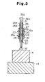
- a toggle clamp according to one embodiment of the present invention will now be described with reference to Figs. 1 to 3.
- a pair of left and right mounting members which are fixed mounting plates 12 in this embodiment, are arranged on an upper surface of a support member, which is a base bracket 11 in this embodiment.
- the mounting plates 12 are fixed to a predetermined position with four bolts 13, which are inserted through the base bracket 11 from below and upward, and nuts 14 screwed to the bolts 13.
- a pressure applying mechanism which is a toggle mechanism 15 in this embodiment, is attached to upper ends of the mounting plates 12.
- a clamp arm 17 extends substantially horizontally.
- the proximal end of the clamp arm 17 is rotatably coupled between the upper ends of the mounting plates 12 with a coupling pin 16. Therefore, the distal end of the clamp arm 17 can rotate back and forth in the vertical direction.
- a pair of manipulation levers 19 extends in a substantially vertical direction.
- the lower ends of the manipulation levers 19 are coupled to the outer surfaces of the upper end of the mounting plates 12 with a coupling pin 18 so that the manipulation levers 19 rotate forward and rearward and the direction of rotation alternates.
- a resin grip 20 is formed at the upper ends of the pair of manipulation levers 19 through insert molding.
- a toggle link 21 is located between the intermediate portion of the clamp arm 17 and the intermediate portion of each manipulation lever 19. Each toggle link 21 is coupled to the clamp arm 17 and the corresponding manipulation lever 19 with coupling pins 22A and 22B.
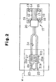
- the clamp arm 17 is branched into a pair of left and right arm pieces 23 as shown in Fig. 2.
- a guide groove 24 is formed between the arm pieces 23 and perforates the arm pieces 23 in the vertical direction.
- a clamp bolt unit 25 is attached to the clamp arm 17 using the arm pieces 23 and the guide groove 24.
- the clamp bolt unit 25 includes a threaded cylinder 26, which is vertically inserted through the guide groove 24.
- a first lock nut 27 and a second lock nut 28 are screwed to an external thread portion 26a formed on the outer circumferential surface of the threaded cylinder 26.
- An upper washer 29 is located between the upper surfaces of the arm pieces 23 and the lower surface of the first lock nut 27.
- a lower washer 30 is located between the lower surfaces of the arm pieces 23 and the upper surface of the second lock nut 28.
- the lower washer 30 and the second lock nut 28 are fixed by welding. As shown in Fig. 3, the left and right sides of each of the upper washer 29 and the lower washer 30 are bent to form a rotation restricting rib 29a or 30a to restrict rotation of the upper washer 29 or the lower washer 30 by engaging with the upper rim or lower rim of the arm pieces 23.
- An internal thread portion 26b is formed vertically through the center of the threaded cylinder 26.
- a clamp bolt 31 is screwed to the internal thread portion 26b so that the vertical position of the clamp bolt 31 is adjustable.
- a head portion 31a is formed at the upper end of the clamp bolt 31.
- a hexagonal manipulation portion which is an engaging hole 31b in this embodiment, is formed in the upper surface of the head portion 31a to be engaged with the distal end of a hexagonal wrench.
- a spherical portion 31c is formed at the lower end of the clamp bolt 31 and is engaged with a pad 32. The spherical portion 31c and the pad 32 are rotatable relative to each other.
- a third lock nut 33 is screwed to the outer circumference of the clamp bolt 31. The third lock nut 33 is securely tightened to the lower surface of the threaded cylinder 26 after the height of the clamp bolt 31 is adjusted so that the clamp bolt 31 is secured to the threaded cylinder 26.
- the guide groove 24 of the clamp arm 17, the first lock nut 27, the second lock nut 28, the upper washer 29, and the lower washer 30 constitute position adjusting means, which adjusts the clamp position of the threaded cylinder 26 and the clamp bolt 31.
- the clamp position is adjusted by moving the clamp bolt unit 25 horizontally along the guide groove 24 to match the position of the workpiece W with the first lock nut 27 loosened. After that, the first lock nut 27 is rotated in the tightening direction to secure the threaded cylinder 26 at the predetermined position of the clamp arm 17.
- the height of the clamp bolt 31 is roughly adjusted by rotating the threaded cylinder 26 so that the pad 32 at the lower end of the clamp bolt 31 contacts the upper surface of the workpiece W.
- the manipulation levers 19 of the toggle mechanism 15 are rotated counterclockwise about the coupling pin 18 to press the clamp bolt 31 and the pad 32 against the upper surface of the workpiece W.
- the coupling pin 22A is located slightly on the right side of a dead line L, which connects the center of the coupling pin 18 and the center of the coupling pin 22B. Therefore, the workpiece W is clamped by a predetermined pressure. However, it is often the case that a desired pressure is not obtained by only rotating the toggle mechanism 15.
- the distal end of the hexagonal wrench is engaged with the engaging hole 31b in the head portion 31a of the clamp bolt 31.
- the hexagonal wrench is rotated, the clamp bolt 31 is rotated and the pressure is adjusted to an appropriate level.
- the preferred embodiment has the following advantages.
- the preferred embodiment may be modified as follows.
- a tubular body 41 having a rectangular cross-section is fitted to the outer circumference of the arm pieces 23 to be slidable in the lateral direction.
- a bolt 42 is screwed to an internal thread portion formed in a side plate of the tubular body 41.
- the distal end of the bolt 42 is pressed against the side surface of one of the arm pieces 23 so that the tubular body 41 is secured to the side surface of the arm piece 23.
- the upper and lower plates of the tubular body 41 function as the upper and lower washers 29, 30.
- Other structures are the same as the preferred embodiment.
- the clamp position of the threaded cylinder 26 and the clamp bolt 31 is adjusted by reciprocating the tubular body 41 along the arm pieces 23 with the bolt 42 loosened. Then, the height of the threaded cylinder 26 is adjusted by loosening the first lock nut 27. Therefore, the height of the threaded cylinder 26 is adjusted in a stable manner.
- Other operations are the same as the preferred embodiment.
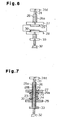
- the shape of the two lock nuts 27, 28 of the preferred embodiment shown in Figs. 1 to 4 is changed to a disk-like form, and the diameter is increased as compared to that of the lock nuts of the preferred embodiment of Fig. 1.
- a knurl is formed on the outer circumferential surface of each lock nut to prevent slipping.
- a manipulation knob 31d for rotational manipulation is integrally or separately formed on the upper end of the clamp bolt 31.
- the third lock nut 33 is also formed as a large diameter disk and a knurl is formed on its outer circumferential surface to enable manipulation of the third lock nut.
- the second lock nut 28 and the lower washer 30 are formed separately.
- the first lock nut 27, the second lock nut 28, the clamp bolt 31, and the third lock nut 33 are easily rotated.
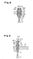
- the internal thread portion 26b is formed at the lower section of the threaded cylinder 26 and a cylindrical accommodating bore 26c is formed at the upper section of the threaded cylinder 26.
- the head portion 31a formed at the upper portion of the clamp bolt 31 is accommodated in the accommodating bore 26c.
- the appearance is simplified.
- the threaded cylinder 26 is screwed to an internal thread portion 17a formed at the distal end of the clamp arm 17.
- the first lock nut 27 is screwed to the external thread portion 26a of the threaded cylinder 26.
- a manipulation piece 26d is screwed to the upper end of the threaded cylinder 26 and is secured to the threaded cylinder 26 by welding.
- the threaded cylinder 26 and the manipulation piece 26d may be integrally formed with each other.
- the clamping force is roughly adjusted by adjusting the height of the threaded cylinder 26 by rotating the manipulation piece 26d formed at the upper end of the threaded cylinder 26 with the first lock nut 27 loosened.
- the clamping force is then finely adjusted by rotating the clamp bolt 31 via the engaging hole 31b formed at the upper end of the clamp bolt 31 while the workpiece W is clamped.
- a rotational manipulation knob (not shown) may be formed at the upper end of the threaded cylinder 26. In this case, the height of the threaded cylinder 26 is easily adjusted.
- a modified embodiment shown in Fig. 10 differs from the preferred embodiment of Fig. 1 in that a solid clamp bolt 26a is provided instead of a combination of the hollow threaded cylinder 26 and the small diameter clamp bolt 31.
- the pad 32 that is the same as the preferred embodiment is attached to the lower end of the clamp bolt 26a via the spherical portion 31c.
- the hexagonal engaging hole 31b for being engaged with the distal end of the hexagonal wrench is formed in the upper end face of the clamp bolt 26.
- the engaging hole 31b functions as a manipulation portion.
- the hexagonal wrench is engaged with the engaging hole 31b of the clamp bolt 26a and rotated.
- the workpiece W is clamped with an appropriate pressure while finely and easily adjusting the pressure of the clamp bolt 26a. Since a wide space above the clamp bolt 26a is used when adjusting the pressure, the operation is easily performed.
- the second lock nut 28 and the lower washer 30 are coupled to each other.
- the second lock nut 28 and the lower washer 30 may be separated from each other.
- a height detector may be a member to be clamped.
- the pressure applying mechanism need not be formed by the toggle mechanism, but may be formed by a cam mechanism.
- a support table for a workpiece for a machine tool may be used as the support member.
- the clamping device may be used as a clamping jig for an assembly line or a welding operation of several types of products.
Landscapes
- Engineering & Computer Science (AREA)
- Mechanical Engineering (AREA)
- Jigs For Machine Tools (AREA)
- Gripping Jigs, Holding Jigs, And Positioning Jigs (AREA)
- Electrical Discharge Machining, Electrochemical Machining, And Combined Machining (AREA)
- Vehicle Body Suspensions (AREA)
- Clamps And Clips (AREA)
Abstract
Description
Claims (11)
- A clamping device comprising a support member for supporting a member to be clamped at a predetermined position, a mounting member attached to the support member, a clamp arm attached to the mounting member to be able to reciprocate with respect to the mounting member, a pressure applying mechanism, which is located between the mounting member and the clamp arm and applies pressure to the clamp arm, and a clamp bolt, which is located on the clamp arm and clamps the member to be clamped between the clamp bolt and the support member, the clamping device being characterized in that,
a threaded cylinder having an external thread portion on the outside and an internal thread portion on the inside is attached to the clamp arm such that the height of the threaded cylinder is adjustable by utilizing the external thread portion, the clamp bolt is screwed to the internal thread portion of the threaded cylinder, and a manipulation portion is provided for rotating the clamp bolt in a state where the member to be clamped is clamped between the clamp bolt and the support member. - The clamping device according to claim 1, wherein a guide groove is formed in the clamp arm, and the threaded cylinder is adjustably attached to the guide groove.
- The clamping device according to claim 2, wherein the threaded cylinder is inserted in the guide groove, a first lock nut and a second lock nut are screwed to the threaded cylinder to sandwich the clamp arm from above and below, and the threaded cylinder is secured at a predetermined position of the clamp arm by securely tightening the first lock nut and the second lock nut to the clamp arm.
- The clamping device according to claim 3, wherein an upper washer is arranged between the clamp arm and the first lock nut and a lower washer is arranged between the clamp arp and the second lock nut, and the upper washer and the lower washer each has a rotation restricting rib for restricting rotation of the upper washer and the lower washer.
- The clamping device according to claim 4, wherein the second lock nut is fixed to the lower surface of the lower washer.
- The clamping arm according to claim 1, wherein the external thread portion of the threaded cylinder is screwed to an internal thread portion formed in the clamp arm, and a first lock nut and a second lock nut are screwed to the external thread portion to secure the threaded cylinder to the clamp arm.
- The clamping device according to any one of claims 1 to 6, wherein an engaging hole is formed at an upper end of the clamp bolt, the engaging hole being engageable with the distal end of a wrench for rotational manipulation.
- The clamping device according to any one of claims 1 to 5, wherein the upper washer and the lower washer are integrally formed with an upper portion and a lower portion of a tubular body, the tubular body being fitted to the clamp arm such that the position of the tubular body is adjustable along the clamp arm, and the tubular body is securely tightened to a side surface of the clamp arm with a bolt.
- The clamping device according to any one of claims 1 to 5, wherein the pressure applying mechanism is a toggle mechanism.
- The clamping device according to any one of claims 1 to 5, wherein a pad is located at the distal end of the clamp bolt, the pad abuts against an upper surface of the member to be clamped and permits the clamp bolt to rotate relative to the pad.
- A clamping device comprising a support member for supporting a member to be clamped at a predetermined position, a mounting member attached to the support member, a clamp arm attached to the mounting member to be able to reciprocate with respect to the mounting member, a pressure applying mechanism, which is located between the mounting member and the clamp arm and applies pressure to the clamp arm, and a clamp bolt, which is located on the clamp arm and clamps the member to be clamped between the clamp bolt and the support member, the clamping device being characterized in that,
the crank bolt is provided on the crank arm such that the position of the crank bolt is adjustable along the crank arm, a manipulation portion is provided on the clamp bolt above the clamp arm, the manipulation portion being used for rotating the clamp bolt in a state where the member to be clamped is clamped between the clamp bolt and the support member.
Applications Claiming Priority (3)
| Application Number | Priority Date | Filing Date | Title |
|---|---|---|---|
| JP2002217157 | 2002-07-25 | ||
| JP2002217157 | 2002-07-25 | ||
| PCT/JP2003/009464 WO2004018154A1 (en) | 2002-07-25 | 2003-07-25 | Clamp device |
Publications (3)
| Publication Number | Publication Date |
|---|---|
| EP1535702A1 true EP1535702A1 (en) | 2005-06-01 |
| EP1535702A4 EP1535702A4 (en) | 2008-11-26 |
| EP1535702B1 EP1535702B1 (en) | 2011-08-03 |
Family
ID=31938716
Family Applications (1)
| Application Number | Title | Priority Date | Filing Date |
|---|---|---|---|
| EP03792638A Expired - Lifetime EP1535702B1 (en) | 2002-07-25 | 2003-07-25 | Clamp device |
Country Status (7)
| Country | Link |
|---|---|
| US (1) | US7213805B2 (en) |
| EP (1) | EP1535702B1 (en) |
| JP (1) | JP3714478B2 (en) |
| KR (1) | KR100956072B1 (en) |
| CN (1) | CN1274461C (en) |
| AT (1) | ATE518625T1 (en) |
| WO (1) | WO2004018154A1 (en) |
Cited By (2)
| Publication number | Priority date | Publication date | Assignee | Title |
|---|---|---|---|---|
| WO2007014647A1 (en) * | 2005-07-30 | 2007-02-08 | Gm Global Technology Operations, Inc. | Pressure device for a clamping system |
| CN105750737A (en) * | 2014-12-18 | 2016-07-13 | 泰科电子(上海)有限公司 | Cutting system |
Families Citing this family (33)
| Publication number | Priority date | Publication date | Assignee | Title |
|---|---|---|---|---|
| US20070108684A1 (en) * | 2005-11-17 | 2007-05-17 | Webb Robert M | Adjustaclamp |
| WO2010045504A1 (en) * | 2008-10-15 | 2010-04-22 | Poole Robert N | Self adjusting toggle clamp |
| US8312598B2 (en) * | 2010-06-15 | 2012-11-20 | On The Level Billiards, Llc | Modular clamp assembly with multiple tool attachments |
| CN102554818A (en) * | 2011-12-08 | 2012-07-11 | 苏州工业园区高登威科技有限公司 | Mounting fixture with slide track positioning judging function |
| DE102012201921A1 (en) * | 2012-02-09 | 2013-08-14 | Andreas Maier Gmbh & Co. Kg | Clamp for a clamping device |
| US8959868B2 (en) * | 2012-09-17 | 2015-02-24 | Bluescope Buildings North America, Inc. | Truss system |
| CN103934812A (en) * | 2013-01-23 | 2014-07-23 | 苏州工业园区高登威科技有限公司 | Manual turnplate positioning device |
| DE102013104413C5 (en) * | 2013-04-30 | 2016-08-11 | Bessey Tool Gmbh & Co. Kg | Toggle clamps |
| DE202013007011U1 (en) * | 2013-08-06 | 2013-09-11 | Bernd Siegmund | clamping tool |
| KR101401268B1 (en) * | 2013-10-31 | 2014-06-02 | 엘오엘 주식회사 | Working device for various type die casting handle |
| CN104384986A (en) * | 2014-10-30 | 2015-03-04 | 马单 | Sphere fixing and clamping device |
| US20150076757A1 (en) * | 2014-11-20 | 2015-03-19 | Caterpillar Inc. | System for securing two components |
| KR200486859Y1 (en) * | 2015-07-30 | 2018-07-09 | 강윤구 | Side Frame Fixing Apparatus of Termpered Glass Door |
| US10800009B2 (en) * | 2016-01-20 | 2020-10-13 | Delaware Capital Formation, Inc. | Toggle clamp |
| KR101709717B1 (en) * | 2016-01-27 | 2017-02-23 | 윤인수 | clamp having multi function |
| CN106425568A (en) * | 2016-10-25 | 2017-02-22 | 江苏北方湖光光电有限公司 | Clamping method and device for balancing locking force from bottom to top |
| US10156065B2 (en) * | 2017-01-17 | 2018-12-18 | Patco, Llc | Stair installation bracket |
| KR101838103B1 (en) * | 2017-02-14 | 2018-04-26 | 김성구 | Clamping Device of overlapping plate |
| US10238899B1 (en) * | 2017-02-28 | 2019-03-26 | Hang On Enterprises, Inc. | Systems and methods for supporting an operator from a building |
| CN107020594B (en) * | 2017-04-10 | 2019-10-25 | 苏州嘉铭塑胶五金制品有限公司 | A press-fitting method of an adjustable toggle press-fitting tool |
| CN107398821B (en) * | 2017-09-12 | 2024-06-11 | 海盐星辰工具有限公司 | Improved fixing device for wrench polishing machine |
| US11318584B2 (en) * | 2017-09-29 | 2022-05-03 | Mitsubishi Heavy Industries, Ltd. | Attachment jig and attachment method |
| JP7063613B2 (en) * | 2017-12-27 | 2022-05-09 | 株式会社エンプラス | Opening and closing mechanism of the opening and closing body |
| US10773272B2 (en) * | 2018-09-21 | 2020-09-15 | The Boeing Company | Zero mask fixtures for parts |
| KR101978435B1 (en) * | 2019-02-16 | 2019-05-14 | 김서현 | Jig for adjusting horizontal level for precise control |
| CN109773705B (en) * | 2019-03-28 | 2024-02-06 | 威猛工业自动化系统(昆山)有限公司 | Synchronous pulley's mounting fixture |
| CN110026579A (en) * | 2019-04-09 | 2019-07-19 | 广东万丰摩轮有限公司 | A kind of drilling tool in wheel valve hole |
| CN109940370A (en) * | 2019-04-18 | 2019-06-28 | 王子萌 | A kind of automation installation self threading pin equipment for installing metal structure |
| CN110216604B (en) * | 2019-05-17 | 2023-06-20 | 优利康达(天津)科技有限公司 | A fairing clamp |
| CN110842589A (en) * | 2019-11-22 | 2020-02-28 | 福州宝井钢材有限公司 | Felt clamping device |
| CN113146498B (en) * | 2021-03-12 | 2022-10-21 | 中国海洋大学 | Multifunctional clamp with pressure sensor, control method and workpiece clamping device |
| CN115213708A (en) * | 2022-06-20 | 2022-10-21 | 中国航发哈尔滨东安发动机有限公司 | Linkage clamping machine adds anchor clamps |
| AT527340A1 (en) * | 2023-07-14 | 2025-01-15 | Gtech Automatisierungstechnik Gmbh | support device |
Family Cites Families (16)
| Publication number | Priority date | Publication date | Assignee | Title |
|---|---|---|---|---|
| JPS50110191A (en) | 1974-02-08 | 1975-08-29 | ||
| DE7605793U1 (en) * | 1976-02-27 | 1976-06-24 | De-Sta-Co Metallerzeugnisse Gmbh, 6000 Frankfurt | Clamping device |
| US4335493A (en) * | 1980-05-02 | 1982-06-22 | Shivers Jr Norman E | Cutting tooth extractor for stump cutting and digging apparatuses |
| US4335873A (en) * | 1980-05-21 | 1982-06-22 | C. J. Edwards Company | Toggle bolt clamp |
| US4828240A (en) * | 1986-09-02 | 1989-05-09 | Te-Co. | Workpiece securing apparatus for a machine tool |
| JPS63136838A (en) | 1986-11-28 | 1988-06-09 | Nec Corp | Infrared-ray remote control receiver |
| JPH0524423Y2 (en) | 1987-03-02 | 1993-06-22 | ||
| JPH01199744A (en) | 1988-02-04 | 1989-08-11 | Toyoda Mach Works Ltd | Device for clamping workpiece |
| JPH0215238U (en) | 1988-07-07 | 1990-01-30 | ||
| KR0131618Y1 (en) * | 1994-07-20 | 1998-12-15 | 전성원 | Trial production car clamping jig |
| JP3566452B2 (en) | 1996-04-25 | 2004-09-15 | 株式会社マキタ | Material fixing device for work table |
| KR19980045750A (en) * | 1996-12-10 | 1998-09-15 | 박병재 | Clamp prefabricated jig |
| US5924685A (en) * | 1997-06-16 | 1999-07-20 | Webb; Robert M. | Adjustable clamp |
| KR100306402B1 (en) * | 1999-06-30 | 2001-09-24 | 이계안 | Jig clamping apparatus to fix vehicle's panel |
| KR200188026Y1 (en) | 2000-01-20 | 2000-07-15 | 김영현 | Toggle clamp |
| JP3086457U (en) | 2001-12-05 | 2002-06-21 | 富士工業株式会社 | Clamper |
-
2003
- 2003-07-25 KR KR1020057001385A patent/KR100956072B1/en not_active Expired - Fee Related
- 2003-07-25 AT AT03792638T patent/ATE518625T1/en not_active IP Right Cessation
- 2003-07-25 US US10/521,934 patent/US7213805B2/en not_active Expired - Fee Related
- 2003-07-25 WO PCT/JP2003/009464 patent/WO2004018154A1/en not_active Ceased
- 2003-07-25 CN CNB038178001A patent/CN1274461C/en not_active Expired - Fee Related
- 2003-07-25 JP JP2004530540A patent/JP3714478B2/en not_active Expired - Lifetime
- 2003-07-25 EP EP03792638A patent/EP1535702B1/en not_active Expired - Lifetime
Cited By (4)
| Publication number | Priority date | Publication date | Assignee | Title |
|---|---|---|---|---|
| WO2007014647A1 (en) * | 2005-07-30 | 2007-02-08 | Gm Global Technology Operations, Inc. | Pressure device for a clamping system |
| CN100566945C (en) * | 2005-07-30 | 2009-12-09 | Gm全球科技运作股份有限公司 | Holder for clamping systems |
| CN105750737A (en) * | 2014-12-18 | 2016-07-13 | 泰科电子(上海)有限公司 | Cutting system |
| CN105750737B (en) * | 2014-12-18 | 2018-01-09 | 泰科电子(上海)有限公司 | Diced system |
Also Published As
| Publication number | Publication date |
|---|---|
| WO2004018154A1 (en) | 2004-03-04 |
| KR100956072B1 (en) | 2010-05-07 |
| US7213805B2 (en) | 2007-05-08 |
| KR20050025679A (en) | 2005-03-14 |
| CN1671512A (en) | 2005-09-21 |
| JP3714478B2 (en) | 2005-11-09 |
| US20060049567A1 (en) | 2006-03-09 |
| EP1535702A4 (en) | 2008-11-26 |
| JPWO2004018154A1 (en) | 2005-12-08 |
| EP1535702B1 (en) | 2011-08-03 |
| CN1274461C (en) | 2006-09-13 |
| ATE518625T1 (en) | 2011-08-15 |
Similar Documents
| Publication | Publication Date | Title |
|---|---|---|
| US7213805B2 (en) | Clamping device | |
| US5924685A (en) | Adjustable clamp | |
| US4787433A (en) | Bead breaking device for tractor tires | |
| JP4201864B2 (en) | Clamping device with toggle mechanism | |
| JP2001087966A (en) | Clamping device | |
| JP2004025332A (en) | Work positioning device for machine tool | |
| CN216860053U (en) | Workpiece holder | |
| JP3137669U (en) | Pachinko machine frame fixing device | |
| GB2345656A (en) | Ball and socket mounting | |
| US20020020955A1 (en) | Clamping device for manually guided electric tools | |
| US4575063A (en) | Vertically adjustable device | |
| JP2003001536A (en) | Work mounting device | |
| JP3075113U (en) | Wheelchair brake adjuster | |
| JP2000127054A (en) | Vice | |
| KR100913390B1 (en) | Clamp for fixing mold | |
| JP2026066930A (en) | Clamping device | |
| JP2618582B2 (en) | Pipe clamp device | |
| US3811654A (en) | Camber and caster adjustment tool | |
| JP3798105B2 (en) | Grip device | |
| KR0136576Y1 (en) | Fixing device for wheel alignment sensor | |
| JP2869251B2 (en) | Side gauge device | |
| JP2601271Y2 (en) | Vise equipment for machine tools | |
| JPH0719641Y2 (en) | Punch and die mounting device for press forming machine | |
| JP6522080B1 (en) | Middle plate mounting device for press brake | |
| CN119282737A (en) | A special tool for milling the back arc of turbine rotor blades |
Legal Events
| Date | Code | Title | Description |
|---|---|---|---|
| PUAI | Public reference made under article 153(3) epc to a published international application that has entered the european phase |
Free format text: ORIGINAL CODE: 0009012 |
|
| 17P | Request for examination filed |
Effective date: 20050222 |
|
| AK | Designated contracting states |
Kind code of ref document: A1 Designated state(s): AT BE BG CH CY CZ DE DK EE ES FI FR GB GR HU IE IT LI LU MC NL PT RO SE SI SK TR |
|
| AX | Request for extension of the european patent |
Extension state: AL LT LV MK |
|
| DAX | Request for extension of the european patent (deleted) | ||
| A4 | Supplementary search report drawn up and despatched |
Effective date: 20081029 |
|
| 17Q | First examination report despatched |
Effective date: 20100122 |
|
| GRAP | Despatch of communication of intention to grant a patent |
Free format text: ORIGINAL CODE: EPIDOSNIGR1 |
|
| GRAS | Grant fee paid |
Free format text: ORIGINAL CODE: EPIDOSNIGR3 |
|
| GRAA | (expected) grant |
Free format text: ORIGINAL CODE: 0009210 |
|
| RIN1 | Information on inventor provided before grant (corrected) |
Inventor name: KUNII, TAKESHI Inventor name: NISHIMURA, EIKICHI |
|
| AK | Designated contracting states |
Kind code of ref document: B1 Designated state(s): AT BE BG CH CY CZ DE DK EE ES FI FR GB GR HU IE IT LI LU MC NL PT RO SE SI SK TR |
|
| REG | Reference to a national code |
Ref country code: GB Ref legal event code: FG4D |
|
| REG | Reference to a national code |
Ref country code: CH Ref legal event code: EP |
|
| REG | Reference to a national code |
Ref country code: IE Ref legal event code: FG4D |
|
| REG | Reference to a national code |
Ref country code: DE Ref legal event code: R096 Ref document number: 60337933 Country of ref document: DE Effective date: 20110929 |
|
| REG | Reference to a national code |
Ref country code: NL Ref legal event code: VDEP Effective date: 20110803 |
|
| PG25 | Lapsed in a contracting state [announced via postgrant information from national office to epo] |
Ref country code: SE Free format text: LAPSE BECAUSE OF FAILURE TO SUBMIT A TRANSLATION OF THE DESCRIPTION OR TO PAY THE FEE WITHIN THE PRESCRIBED TIME-LIMIT Effective date: 20110803 Ref country code: PT Free format text: LAPSE BECAUSE OF FAILURE TO SUBMIT A TRANSLATION OF THE DESCRIPTION OR TO PAY THE FEE WITHIN THE PRESCRIBED TIME-LIMIT Effective date: 20111205 Ref country code: NL Free format text: LAPSE BECAUSE OF FAILURE TO SUBMIT A TRANSLATION OF THE DESCRIPTION OR TO PAY THE FEE WITHIN THE PRESCRIBED TIME-LIMIT Effective date: 20110803 Ref country code: FI Free format text: LAPSE BECAUSE OF FAILURE TO SUBMIT A TRANSLATION OF THE DESCRIPTION OR TO PAY THE FEE WITHIN THE PRESCRIBED TIME-LIMIT Effective date: 20110803 |
|
| REG | Reference to a national code |
Ref country code: AT Ref legal event code: MK05 Ref document number: 518625 Country of ref document: AT Kind code of ref document: T Effective date: 20110803 |
|
| PG25 | Lapsed in a contracting state [announced via postgrant information from national office to epo] |
Ref country code: CY Free format text: LAPSE BECAUSE OF FAILURE TO SUBMIT A TRANSLATION OF THE DESCRIPTION OR TO PAY THE FEE WITHIN THE PRESCRIBED TIME-LIMIT Effective date: 20110803 Ref country code: AT Free format text: LAPSE BECAUSE OF FAILURE TO SUBMIT A TRANSLATION OF THE DESCRIPTION OR TO PAY THE FEE WITHIN THE PRESCRIBED TIME-LIMIT Effective date: 20110803 Ref country code: SI Free format text: LAPSE BECAUSE OF FAILURE TO SUBMIT A TRANSLATION OF THE DESCRIPTION OR TO PAY THE FEE WITHIN THE PRESCRIBED TIME-LIMIT Effective date: 20110803 Ref country code: GR Free format text: LAPSE BECAUSE OF FAILURE TO SUBMIT A TRANSLATION OF THE DESCRIPTION OR TO PAY THE FEE WITHIN THE PRESCRIBED TIME-LIMIT Effective date: 20111104 |
|
| PG25 | Lapsed in a contracting state [announced via postgrant information from national office to epo] |
Ref country code: BE Free format text: LAPSE BECAUSE OF FAILURE TO SUBMIT A TRANSLATION OF THE DESCRIPTION OR TO PAY THE FEE WITHIN THE PRESCRIBED TIME-LIMIT Effective date: 20110803 |
|
| PG25 | Lapsed in a contracting state [announced via postgrant information from national office to epo] |
Ref country code: CZ Free format text: LAPSE BECAUSE OF FAILURE TO SUBMIT A TRANSLATION OF THE DESCRIPTION OR TO PAY THE FEE WITHIN THE PRESCRIBED TIME-LIMIT Effective date: 20110803 Ref country code: SK Free format text: LAPSE BECAUSE OF FAILURE TO SUBMIT A TRANSLATION OF THE DESCRIPTION OR TO PAY THE FEE WITHIN THE PRESCRIBED TIME-LIMIT Effective date: 20110803 |
|
| PG25 | Lapsed in a contracting state [announced via postgrant information from national office to epo] |
Ref country code: EE Free format text: LAPSE BECAUSE OF FAILURE TO SUBMIT A TRANSLATION OF THE DESCRIPTION OR TO PAY THE FEE WITHIN THE PRESCRIBED TIME-LIMIT Effective date: 20110803 Ref country code: IT Free format text: LAPSE BECAUSE OF FAILURE TO SUBMIT A TRANSLATION OF THE DESCRIPTION OR TO PAY THE FEE WITHIN THE PRESCRIBED TIME-LIMIT Effective date: 20110803 Ref country code: RO Free format text: LAPSE BECAUSE OF FAILURE TO SUBMIT A TRANSLATION OF THE DESCRIPTION OR TO PAY THE FEE WITHIN THE PRESCRIBED TIME-LIMIT Effective date: 20110803 |
|
| PLBE | No opposition filed within time limit |
Free format text: ORIGINAL CODE: 0009261 |
|
| STAA | Information on the status of an ep patent application or granted ep patent |
Free format text: STATUS: NO OPPOSITION FILED WITHIN TIME LIMIT |
|
| PG25 | Lapsed in a contracting state [announced via postgrant information from national office to epo] |
Ref country code: DK Free format text: LAPSE BECAUSE OF FAILURE TO SUBMIT A TRANSLATION OF THE DESCRIPTION OR TO PAY THE FEE WITHIN THE PRESCRIBED TIME-LIMIT Effective date: 20110803 |
|
| 26N | No opposition filed |
Effective date: 20120504 |
|
| REG | Reference to a national code |
Ref country code: DE Ref legal event code: R097 Ref document number: 60337933 Country of ref document: DE Effective date: 20120504 |
|
| PG25 | Lapsed in a contracting state [announced via postgrant information from national office to epo] |
Ref country code: MC Free format text: LAPSE BECAUSE OF NON-PAYMENT OF DUE FEES Effective date: 20120731 |
|
| REG | Reference to a national code |
Ref country code: CH Ref legal event code: PL |
|
| PG25 | Lapsed in a contracting state [announced via postgrant information from national office to epo] |
Ref country code: LI Free format text: LAPSE BECAUSE OF NON-PAYMENT OF DUE FEES Effective date: 20120731 Ref country code: ES Free format text: LAPSE BECAUSE OF FAILURE TO SUBMIT A TRANSLATION OF THE DESCRIPTION OR TO PAY THE FEE WITHIN THE PRESCRIBED TIME-LIMIT Effective date: 20111114 Ref country code: CH Free format text: LAPSE BECAUSE OF NON-PAYMENT OF DUE FEES Effective date: 20120731 |
|
| REG | Reference to a national code |
Ref country code: IE Ref legal event code: MM4A |
|
| PG25 | Lapsed in a contracting state [announced via postgrant information from national office to epo] |
Ref country code: BG Free format text: LAPSE BECAUSE OF FAILURE TO SUBMIT A TRANSLATION OF THE DESCRIPTION OR TO PAY THE FEE WITHIN THE PRESCRIBED TIME-LIMIT Effective date: 20111103 |
|
| PG25 | Lapsed in a contracting state [announced via postgrant information from national office to epo] |
Ref country code: IE Free format text: LAPSE BECAUSE OF NON-PAYMENT OF DUE FEES Effective date: 20120725 |
|
| PG25 | Lapsed in a contracting state [announced via postgrant information from national office to epo] |
Ref country code: TR Free format text: LAPSE BECAUSE OF FAILURE TO SUBMIT A TRANSLATION OF THE DESCRIPTION OR TO PAY THE FEE WITHIN THE PRESCRIBED TIME-LIMIT Effective date: 20110803 |
|
| PG25 | Lapsed in a contracting state [announced via postgrant information from national office to epo] |
Ref country code: LU Free format text: LAPSE BECAUSE OF NON-PAYMENT OF DUE FEES Effective date: 20120725 |
|
| PG25 | Lapsed in a contracting state [announced via postgrant information from national office to epo] |
Ref country code: HU Free format text: LAPSE BECAUSE OF FAILURE TO SUBMIT A TRANSLATION OF THE DESCRIPTION OR TO PAY THE FEE WITHIN THE PRESCRIBED TIME-LIMIT Effective date: 20030725 |
|
| PGFP | Annual fee paid to national office [announced via postgrant information from national office to epo] |
Ref country code: DE Payment date: 20140801 Year of fee payment: 12 |
|
| PGFP | Annual fee paid to national office [announced via postgrant information from national office to epo] |
Ref country code: GB Payment date: 20140731 Year of fee payment: 12 |
|
| REG | Reference to a national code |
Ref country code: FR Ref legal event code: PLFP Year of fee payment: 13 |
|
| PGFP | Annual fee paid to national office [announced via postgrant information from national office to epo] |
Ref country code: FR Payment date: 20150731 Year of fee payment: 13 |
|
| REG | Reference to a national code |
Ref country code: DE Ref legal event code: R119 Ref document number: 60337933 Country of ref document: DE |
|
| GBPC | Gb: european patent ceased through non-payment of renewal fee |
Effective date: 20150725 |
|
| PG25 | Lapsed in a contracting state [announced via postgrant information from national office to epo] |
Ref country code: DE Free format text: LAPSE BECAUSE OF NON-PAYMENT OF DUE FEES Effective date: 20160202 Ref country code: GB Free format text: LAPSE BECAUSE OF NON-PAYMENT OF DUE FEES Effective date: 20150725 |
|
| PG25 | Lapsed in a contracting state [announced via postgrant information from national office to epo] |
Ref country code: FR Free format text: LAPSE BECAUSE OF NON-PAYMENT OF DUE FEES Effective date: 20160801 |
|
| REG | Reference to a national code |
Ref country code: FR Ref legal event code: ST Effective date: 20170331 |