EP1535593A1 - Movable bed - Google Patents
Movable bed Download PDFInfo
- Publication number
- EP1535593A1 EP1535593A1 EP03794110A EP03794110A EP1535593A1 EP 1535593 A1 EP1535593 A1 EP 1535593A1 EP 03794110 A EP03794110 A EP 03794110A EP 03794110 A EP03794110 A EP 03794110A EP 1535593 A1 EP1535593 A1 EP 1535593A1
- Authority
- EP
- European Patent Office
- Prior art keywords
- platform
- load
- bed
- tilt
- adjustable bed
- Prior art date
- Legal status (The legal status is an assumption and is not a legal conclusion. Google has not performed a legal analysis and makes no representation as to the accuracy of the status listed.)
- Withdrawn
Links
- 230000006835 compression Effects 0.000 claims abstract description 26
- 238000007906 compression Methods 0.000 claims abstract description 26
- 230000007246 mechanism Effects 0.000 claims abstract description 24
- 238000005096 rolling process Methods 0.000 description 18
- 210000000689 upper leg Anatomy 0.000 description 17
- 210000001699 lower leg Anatomy 0.000 description 15
- 230000008878 coupling Effects 0.000 description 12
- 238000010168 coupling process Methods 0.000 description 12
- 238000005859 coupling reaction Methods 0.000 description 12
- 230000003014 reinforcing effect Effects 0.000 description 7
- 210000002414 leg Anatomy 0.000 description 5
- 210000001624 hip Anatomy 0.000 description 4
- 208000019901 Anxiety disease Diseases 0.000 description 3
- 230000036506 anxiety Effects 0.000 description 3
- 230000008859 change Effects 0.000 description 3
- 230000003028 elevating effect Effects 0.000 description 3
- 210000003127 knee Anatomy 0.000 description 3
- 230000000474 nursing effect Effects 0.000 description 3
- 208000004210 Pressure Ulcer Diseases 0.000 description 2
- 238000010276 construction Methods 0.000 description 2
- 230000000694 effects Effects 0.000 description 2
- 230000001144 postural effect Effects 0.000 description 2
- 125000006850 spacer group Chemical group 0.000 description 2
- 208000012661 Dyskinesia Diseases 0.000 description 1
- 230000001010 compromised effect Effects 0.000 description 1
- 230000006872 improvement Effects 0.000 description 1
- 238000003780 insertion Methods 0.000 description 1
- 230000037431 insertion Effects 0.000 description 1
- 238000004519 manufacturing process Methods 0.000 description 1
- 230000013011 mating Effects 0.000 description 1
- 238000000034 method Methods 0.000 description 1
- 230000000284 resting effect Effects 0.000 description 1
- 238000003466 welding Methods 0.000 description 1
Images


Classifications
-
- A—HUMAN NECESSITIES
- A61—MEDICAL OR VETERINARY SCIENCE; HYGIENE
- A61G—TRANSPORT, PERSONAL CONVEYANCES, OR ACCOMMODATION SPECIALLY ADAPTED FOR PATIENTS OR DISABLED PERSONS; OPERATING TABLES OR CHAIRS; CHAIRS FOR DENTISTRY; FUNERAL DEVICES
- A61G7/00—Beds specially adapted for nursing; Devices for lifting patients or disabled persons
- A61G7/001—Beds specially adapted for nursing; Devices for lifting patients or disabled persons with means for turning-over the patient
-
- A—HUMAN NECESSITIES
- A61—MEDICAL OR VETERINARY SCIENCE; HYGIENE
- A61G—TRANSPORT, PERSONAL CONVEYANCES, OR ACCOMMODATION SPECIALLY ADAPTED FOR PATIENTS OR DISABLED PERSONS; OPERATING TABLES OR CHAIRS; CHAIRS FOR DENTISTRY; FUNERAL DEVICES
- A61G7/00—Beds specially adapted for nursing; Devices for lifting patients or disabled persons
- A61G7/002—Beds specially adapted for nursing; Devices for lifting patients or disabled persons having adjustable mattress frame
- A61G7/008—Beds specially adapted for nursing; Devices for lifting patients or disabled persons having adjustable mattress frame tiltable around longitudinal axis, e.g. for rolling
-
- A—HUMAN NECESSITIES
- A61—MEDICAL OR VETERINARY SCIENCE; HYGIENE
- A61G—TRANSPORT, PERSONAL CONVEYANCES, OR ACCOMMODATION SPECIALLY ADAPTED FOR PATIENTS OR DISABLED PERSONS; OPERATING TABLES OR CHAIRS; CHAIRS FOR DENTISTRY; FUNERAL DEVICES
- A61G7/00—Beds specially adapted for nursing; Devices for lifting patients or disabled persons
- A61G7/002—Beds specially adapted for nursing; Devices for lifting patients or disabled persons having adjustable mattress frame
- A61G7/015—Beds specially adapted for nursing; Devices for lifting patients or disabled persons having adjustable mattress frame divided into different adjustable sections, e.g. for Gatch position
-
- A—HUMAN NECESSITIES
- A61—MEDICAL OR VETERINARY SCIENCE; HYGIENE
- A61G—TRANSPORT, PERSONAL CONVEYANCES, OR ACCOMMODATION SPECIALLY ADAPTED FOR PATIENTS OR DISABLED PERSONS; OPERATING TABLES OR CHAIRS; CHAIRS FOR DENTISTRY; FUNERAL DEVICES
- A61G2203/00—General characteristics of devices
- A61G2203/10—General characteristics of devices characterised by specific control means, e.g. for adjustment or steering
- A61G2203/12—Remote controls
Definitions
- the present invention relates to adjustable beds for use in nursing care and the like, and particularly to an adjustable bed having a platform that tilts toward both sides in a width direction of the bed.
- adjustable beds used as nursing-care beds include a turning mechanism to assist in the turning of care recipients in order to prevent the occurrence of decubitus ulcers, more commonly known as bedsores.
- This turning mechanism operates, for example, to tilt a platform surface of the bed to both the left and right sides (width direction), and turn a care recipient lying on the bed in a direction of the incline so as to assist in postural changes.
- Figs.13A to 13C show a nursing-care bed assisting the turning of a care recipient as seen from the head end of the bed.
- the bed given here includes, as shown in Fig.13A, a platform 1015 having a platform surface, and a fixed stage 1030 that supports platform 1015.
- Fixed stage 1030 includes a support base 1032 on which platform 1015 is placed, and elevation units 1035L/1035R that elevate the left and right sides of platform 1015 independently.
- Underneath platform 1015 is attached a left/right pair of rollers 1202 and 1203 in a longitudinal direction, platform 1015 resting on support base 1032 via roller 1202/1203.
- platform 1015 When, as shown in Figs.13B and 13C, one side (left side) of platform 1015 is raised by elevation unit 1035L in a bed having this structure, roller 1202 on the other side (right side) rolls over support base 1032 toward the raised side (left side), and platform 1015 tilts (rotates) in an x direction with the center of roller 1202 as the rotational center.
- a rotational moment M1 generated around the rotational center i.e. center of left-side roller 1202
- rotational moment M1 acts against the elevation of the side of platform 1015 (opposite of x direction in Fig.13B).
- elevation unit 1035L is subject to a compression load from platform 1015.
- the adjustable bed given here is mostly used by elderly people in need of nursing care and people suffering serious illnesses. As such, jarring motion and variations in the tilt speed that occur during the operation of platform 1015 may, for example, wake up a bed user who is sleeping. Since the possibility exists of stress and psychological anxiety being caused to the bed user, this area of adjustable beds is still in need of improvement.
- the present invention which arose in view of the above problems, aims to provide an adjustable bed capable of tilting a platform of the bed so as not to subject a bed user to unnecessary stress.
- an adjustable bed pertaining the present invention includes a laterally tiltable platform; a tilt mechanism adapted to tilt the platform laterally; and a load-applying unit adapted to apply, in a state in which the platform is tilted within a predetermined angle range during operation of the tilt mechanism, a load to the platform in a direction that suppresses an expansion of the tilt angle, so as to prevent one of a compression load and a tension load exerted on the tilt mechanism by the platform from reversing to the other load type.
- the predetermined angle range may include, specifically, an angle at which a gravitational center of the platform during the tilt operation traverses a vertical line containing a rotational center of the platform with the load-applying unit in a non-operational state. More specifically, the range may be from 30 degrees to 90 degrees inclusive, with reference to the platform in a horizontal state.
- the load on the tilt mechanism from the platform during operation is, according to these structures, maintained throughout as either a compression load or a tension load, it is possible to prevent intermittent operation of the adjustable bed. Since this construction preventing load reversals means that reversals in the load on the coupling parts do not occur with the present invention, even if, for instance, play exists structurally in the construction of the adjustable bed, particularly in the coupling parts of the tilt mechanism, it is possible to effectively prevent the jerkiness and sudden variations in speed of conventional beds during operation caused by this play.
- the prevent invention thus enables the bed user to feel relaxed about using the bed, without any stress or psychological anxiety being caused.
- the load-applying unit may be constituted from a tension spring.
- the load-applying unit may have a first member and a second member that, in combination, extend in proportion to a slope of the platform, and a compression spring disposed so as to apply a load in a direction that retracts the combination of the first and second members when the slope of the platform reaches a predetermined tilt angle, and the predetermined tilt angle may be an angle immediately prior to an angle at which a rotational moment around a rotational center that acts on the platform, reverses direction due to self weight during the operation of the tilt mechanism.
- the load-applying unit may include a compression spring adapted to apply, at a start of the tilting operation, a load in a direction that extends the combination of the first and second members.
- the tilt mechanism may include an elevation unit disposed on either side of the platform, in order to elevate the platform up and down, and the platform may be tilted laterally by driving one of the elevation units.
- the platform may be placed on a support base via a roller disposed on either side of the platform, and when one side of the platform is raised by the elevation unit corresponding to the side, the roller on the other side may roll over the support base toward the side being raised, and the platform may tilt with a center of the roller on the other side as a rotational center.
- Fig.1 is a schematic view showing a structure of a turning bed 1 pertaining to an embodiment 1.
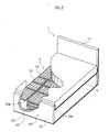
- Fig. 2 is a cutaway perspective view of a section of turning bed 1.
- FIG. 1 includes, as shown in Figs.1 and 2, a main body 2 of the bed that includes an adjustable platform surface 13 (see Fig.2), a mattress 3 placed on platform surface 13, and a remote controller 4 for operating platform surface 13.
- a main body 2 of the bed that includes an adjustable platform surface 13 (see Fig.2), a mattress 3 placed on platform surface 13, and a remote controller 4 for operating platform surface 13.
- the care recipient By operating remote controller 4, the care recipient, for example, raises their upper body from a supine position (hereinafter, “sitting-up position”), raises their knees (hereinafter, “knee-break”), and furthermore, as shown in Fig. 1, changes their posture from a supine position to a left lateral position, for example.
- a posture that includes at least one of the sitting-up and knee-break positions is referred to as a "flexion position"
- the tilting of platform surface 13 of main body 2 in a longitudinal direction so as to obtain such a posture is referred to as "flexing" platform surface 13.
- Remote controller 4 is provided as operating units for flexing, elevating, and rolling platform surface 13 of main body 2, when changing the position or posture of a care recipient.
- Remote controller 4 has a height operating unit that elevates platform surface 13 up and down to adjust the height, a head operating unit that lifts the care recipient's upper body, a leg operating unit that flexes the care recipient's knees, and a turning operating unit that turns the care recipient to the left or right.
- platform surface 13 flexes to assist the care recipient achieve sitting-up and knee-break positions, and platform surface 13 also rolls to the left/right to assist the care recipient with turning from a supine to a lateral position.
- Main body 2 as shown in Fig.2, includes an inner bed frame 10 structuring adjustable platform surface 13, an adjustable stage 20 for moving bed frame 10, a fixed stage 30 that supports adjustable stage 20, and an outer bed frame 40 that encompasses the above components 10, 20, 30 and 40.
- the platform is here constituted from inner bed frame 10 and adjustable stage 20.
- a section of platform surface 13 on the left side rises to support the care recipient from the side (left side in Fig.1), in order to prevent the care recipient from falling out of bed 1.
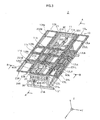
- Fig. 3 is a perspective view showing main body 2 without outer bed frame 40.
- the following description relates to the structure of inner bed frame 10, adjustable stage 20, and fixed stage 30.
- Inner bed frame 10 is partitioned in three - middle section 11, right-side section 12R, and left-side section 12L - in a crosswise direction of bed 1 ( y direction in Fig. 3; also referred to as a "latitudinal direction”), in order to, for example, flex/roll platform surface 13 as described above, and raise the side sections when platform surface 13 is rolled. Furthermore, sections 11, 12R and 12L are each partitioned, in a lengthwise direction ( x direction in Fig.3; also referred to as a "longitudinal direction") of bed 1, into four sections corresponding to the back, hip, upper leg, and lower leg regions of a care recipient's body. Note that in the present specification, the directions indicating left/right are from the viewpoint of a care recipient lying on bed 1.
- middle section 11 With respect to middle section 11 positioned in a middle of bed 1 in the crosswise direction, the part corresponding to the care recipient's back is, as shown in Fig.3, referred to as a back portion 11a. Likewise, the parts corresponding to the hip, upper-leg, and lower-leg regions are referred to as a hip portion 11b, an upper-leg portion 11c, and a lower-leg portion 11d.
- a back portion 12Ra the parts of right-side section 12R corresponding respectively to the care recipient's back, hip, upper-leg, and lower-leg regions
- a back portion 12Rb the parts of right-side section 12R corresponding respectively to the care recipient's back, hip, upper-leg, and lower-leg regions
- the parts of right-side section 12L corresponding respectively to the back, hip, upper-leg, and lower-leg regions are referred to as a back portion 12La, a hip portion 12Lb, an upper-leg portion 12Lc, and a lower-leg portion 12Ld.
- “middle section 11”, used hereinafter, means the entirety including back portion 11a, hip portion 11b, upper-leg portion 11c, and lower-leg portion 11d (four parts).
- “right-side section 12R” means the entirety including back portion 12Ra, hip portion 12Rb, upper-leg portion 12Rc, and lower-leg portion 12Rd (four parts)
- “left/right side sections 12L/R” means the entirety including back portion 12La, hip portion 12Lb, upper-leg portion 12Lc, lower-leg portion 12Ld, back portion 12Ra, hip portion 12Rb, upper-leg portion 12Rc, and lower-leg portion 12Rd (eight parts).
- a wire mesh is, as shown in Fig.2, stretched across the surface (platform surface 13) of bed frame 10, although in Fig.3, this wire mesh has been omitted so as to clearly represent the structures of other members, parts, and the like.
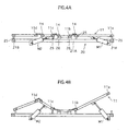
- Figs.4A and 4B are longitudinal sectional views of bed frame 10 and adjustable stage 20 along the A-A line in Fig. 3, Fig.4A showing bed frame 10 in a horizontal state, and Fig.4B showing bed frame 10 in a flexed state.
- Middle sections 11a-11d are, as shown in Fig.4A, supported by adjustable stage 20 with a gap therebetween (i.e. via spacers 25, for example).
- Hip portion 11b is fixed to spacers 26, which are secured to adjustable stage 20, by welding or the like.
- Bed frame is thus secured to adjustable stage 20.
- Middle sections 11a-11d are each pivotally coupled via hinges 14 to middle sections adjacent in the lengthwise direction of bed 1. Since the axial pins of hinges 14 are disposed in the crosswise direction (i.e. orthogonal to the page), not only do back portion 11a and upper-leg portion 11c both flex in relation to hip portion 11b, but lower-leg portion 11d flexes with the flexing of upper-leg portion 11c.
- actuator M1 and M2 which operate in accordance with button operations to the head and leg operating units of remote controller 4.
- actuator M1 in a vicinity of the care recipient's head is referred to as head-end actuator M1
- actuator M2 in a vicinity of the care recipient's legs is referred to as foot-end actuator M2.
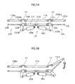
- Figs.5A and 5B are transverse sectional views of bed frame 10 and adjustable stage 20 along the B-B line in Fig.3, Fig.5A showing bed frame 10 in a horizontal state, and Fig.5A showing left-side section 12L in a raised state.
- Middle sections 11a-11d are, as shown in Figs.3, 5A and 5B, pivotally coupled via hinges 15 to right/left-side sections 12Ra-12Rd and 12La-12Ld on the left and right. Since the axial pins of hinges 15 are disposed in the lengthwise direction, side sections 12R and 12L can be raised relative to middle sections 11. Moreover, the raising of side sections 12R and 12L is, as shown in Fig. 5B, performed by right/left support frames 24R/24L, which are raised by actuators M3R and M3L that operate in accordance with button operations to the turning operating unit of remote controller 4.
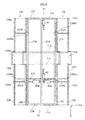
- Fig.6 is a plan view of main body 2 with bed frame 10 in Fig. 3 having been removed
- Fig.7 is a perspective view of main body 2 with bed frame 10 in Fig.3 having been removed.
- Adjustable stage 20 includes, as shown in Fig.3 and Figs.5 to 7, a rectangular stage frame 21 that is long in the longitudinal direction of bed 1, and support frames 24R/24L on the left/right that support and raise right/left side sections 12R/12L of bed frame 10. Note that in Fig.7 depiction of support frame 24L has been omitted.
- Stage frame 21, as shown in Fig.6, includes a pair of lengthwise members 21R/21L that are parallel in the longitudinal direction, and a pair of crosswise members 21F/21B that are coupled in the latitudinal direction to both ends of the pair of lengthwise members 21R/21L.
- Frame 21 is reinforced by a lengthwise reinforcing member 21A that couples the pair of crosswise members 21F/21B at a substantial center between lengthwise members 21R/21L, and a crosswise reinforcing member 21C that couples lengthwise reinforcing member 21A with lengthwise members 21R/21L at the foot-end of bed 1.
- Head-end actuator M1 which has a rod coupled at one end to back portion 11a, is, as shown also in Figs.4A and 4B, attached to a head-end of lengthwise reinforcing member 21A.
- Back portion 11a which assists the care recipient achieve a sitting-up position, is raised/lowered (flexed), as shown in Fig.4B, by extending and retracting this rod.
- foot-end actuator M2 which has a rod coupled at one end to back portion 11c, is, as also shown in Figs.4A and 4B, attached to a foot-end of lengthwise reinforcing member 21A.
- Upper-leg portion 11c which assists the care recipient achieve a knee-break position, is raised/lowered (flexed), as shown in Fig.4B, by extending and retracting this rod.
- Support frames 24R/24L are, as shown in Fig.3 and Figs.5 to 7, attached to lengthwise members 21R/21L on the right and left of stage frame 21 via coupling members 236Ra/236Rb and 236La/236Lb.
- support frames 24R/24L have the same structure and differ only with respect to positioning (i.e. right/left), the following description relates only to support frame 24R on the right side. Note that the reference numbers of the various members structuring left support frame 24L are obtained by changing the "R" at the end of the reference numbers used with right support frame 24R described below to an "L".
- Support frame 24R is constituted, in a ladder-shape, from a pair of lengthwise struts 22R and 23R disposed in a lengthwise direction, and two crosswise struts 231R and 232R that couple the pair of lengthwise struts 22R and 23R in the crosswise direction.
- lengthwise strut 22R on the inside being pivotally supported by coupling members 236Ra/236Rb secured to lengthwise member 21R of stage frame 21
- support frame 24R is able to pivot with lengthwise strut 22R as the central axis.
- Extended parts 235R/235L which extend downwards, are, as shown in Figs.5 and 5B, secured to lengthwise struts 22R/22L, and the rods of right/left actuators M3R/M3L, which extend and retract in the crosswise direction, are secured to these extended parts 235R/235L.
- support frames 24R/24L pivot around the axial center of lengthwise struts 22R/22L on the inside and are raised, which supports and raises right/left side sections 12R/12L from underneath.
- right/left actuators M3R/M3L are, as also shown in Figs.5A and 5B, attached to lengthwise reinforcing member 21A and crosswise reinforcing member 21C, and operated by the operation of operation buttons on the turning operating unit of remote controller 4, for example.
- Fixed stage 30 is, as shown in Figs. 3 and 7, formed from a support base 31 that supports adjustable stage 20, and a right/left pair of elevation units 35R/35L for elevating adjustable stage 20 up and down, and tilting the adjustable stage to the right/left.
- Support base 31 is constituted from a pair of erection frames 32B/32F disposed one at each end in a lengthwise direction, and a pair of coupling members 33R/33L coupling erection frames 32B/32F in a longitudinal direction.
- Elevation units 35R/35L are provided on both the right and left sides of support base 31 between erection frames 32B/32F. Elevation units 35R/35L on both the left and right are operated when elevating adjustable stage 20, and one of elevation units 35R/35L is operated when tilting adjustable stage 20 to the left or right.
- rollers 200, 201, 202 and 203 that roll to the right and left on top surfaces 300 and 301 of erection frames 32B/32F are attached to an underside of adjustable stage 20, the rotational center (axis) when adjustable stage 20 is tilted being a line segment connecting the centers of rollers (e.g. rollers 200/202) that roll over top surfaces 300 and 301 of erection frames 32B/32F.
- Fig.8 is a perspective view of fixed stage 30 with adjustable stage 20 in an elevated state
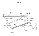
- Fig.9 is a lateral view of elevation unit 35L from the right side.
- Elevation units 35R/35L will now be described. The following description relates to elevation unit 35L, since units 35R/35L differ only in their positioning on the right and left sides.
- Elevation unit 35L is, as shown in Fig.7, structured so as to receive a stage bar 27L attached to lengthwise member 21L of adjustable stage 20 from below using bar receiver 36L. Adjustable stage 20 is raised as a result of bar receiver 36L being raised in this state (the raising of bar receiver 36L is also referred to as "extending" the elevation unit).
- stage bars 27R/27L rotate smoothly within bar receiver 36R/36L when rolling adjustable stage 20
- stage bars 27R/27L are, for example, circular in cross-section, while bar receiver 36R/36L are correspondingly U-shaped in cross-section.
- Coupled to bar receiver 36L is, as shown Fig.8, a pair of support arms 354L/356L, freely raisable/lowerable at both ends in a lengthwise direction of bar receiver 36L, which is elevated by the up/down movement of these support arms 354L/356L.
- the lower ends of support arms 354L/356L are structured to move within a guiding member 32L in a lengthwise direction, when support arms 354L/356L are raised/lowered, thus enabling bar receiver 36L to be elevated in a perpendicular (up/down) direction.
- Support arms 354L/356L are pivotally coupled to the flexed part of L-shaped members 351L and 352L, which are coupled at one end to guiding member 32L.
- the ends of L-shaped members 351L and 352L opposite the ends coupled to guiding member 32L are coupled to a horizontal link member 353L, and an actuator M4L is attached at an angle between this link member 353L and bar receiver 36L.
- actuator M4L By extending/retracting the rod of actuator M4L, L-shaped members 351L and 352L pivot on the coupling points with guiding member 32L, and support arms 354L/356L coupled to L-shaped members 351L and 352L are raised/lowered.
- stage bars 27R/27L do not dislodge from bar receivers 36R/36L once bar receivers 36R/36L have received stage bars 27R/27L from below.
- a safety mechanism that includes a belt, a chain, a spring and the like, is provided between stage bars 27R/27L and bar receivers 36R/36L.
- a load-applying unit 50 that applies a load in a direction that reduces the incline when adjustable stage 20 is tilted within a range of at least 30 degrees to 90 degrees inclusive, with reference to a horizontal state of the platform, for example.
- This range includes an angle at which the position acted on by a resultant of the gravitation forces of adjustable stage 20 and the care recipient traverses (i.e. crosses or passes through) a vertical line C containing the rotational center.
- load-applying unit 50 applies a load in a direction (downward) that reduces the lift of bar receiver 36L included in elevation unit 35L.
- the tilt angle of the platform when the position acted on by the resultant of the gravitation forces of adjustable stage 20 and the care recipient traverses vertical line C containing the rotational center varies depending, for instance, on the care recipient's weight and position on the bed. Considering these factors that include the care recipient's weight and position, a tilt angle of 30 degrees is the smallest angle for use of bed 1 under normal conditions. Also, in relation to the maximum angle, it is difficult to imagine bed 1 being used beyond a tilt angle of 90 degrees in terms of safety.
- load-applying unit 50 is constituted from a tension spring SP1L attached to the pair of support arms 354L/356L.
- Tension spring SP1L is disposed substantially parallel to the direction in which the rod of actuator M4L extends/retracts, and applies a load on elevation units 35R/35L when the platform begins to roll.
- the rod of actuator M4L is extended/retracted as a result of the height and turning operating units of remote controller 4 being operated.
- Outer bed frame 40 is, as shown in Figs.1 and 2, constituted from a headboard 41 disposed at the head-end of bed 1, a footboard 42 disposed at the foot-end of bed 1, and a left/right pair of sideboards 43R/43L that couple headboard 41 and footboard 42 below the sides of a mattress 3.
- Headboard 41, footboard 42, and sideboards 43R/43L enhance the design of bed 1, as well as preventing the bed user from being mistakenly sandwiched between the surface on which bed 1 is established (e.g. floor) and the raised bed frame 10, for instance.
- Described here is an exemplary operation when turning a care recipient lying supine to a left lateral position, as shown in Fig.1.
- the rods of head and foot-end actuator M1 and M2 are extended, and the sitting-up and knee-break operations are performed.
- the most stable posture for a care recipient lying supine is a flexion position with knees bent and hips flexed, the above sitting-up and knee-break operations being performed to obtain this flexion position.
- actuators M4R attached to elevation unit 35R on the right side is extended, and bar receiver 36R rises, receiving stage bar 27R.
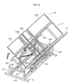
- adjustable stage 20 as shown in Fig.10, begins to roll to the left.
- the platform is tilted by right-side elevation unit 35R, raising the right side of the platform.
- Figs.11A to 11C schematically show a rotational moment that occurs when adjustable stage 20 is rolled to face the right side, Fig.11A showing adjustable stage 20 in a horizontal state prior to rolling, Fig.11B showing a state after the rolling has started, and Fig.11C showing a state of the rolling beyond that shown in Fig.11B.
- Elevation unit 35L elevates bar receiver 36L so that a rotational moment greater than the above rotational moment M1 acts of the rotational center.
- Resultant W of the gravitational forces of bed frame 10, adjustable stage 20, and the care recipient referred to here equates of load-applying unit 50 not being attached (i.e. inactive).
- tension spring SP1L attached to elevation unit 35L applies a load P1 in a direction opposite to the direction in which elevation unit 35L extends when W , which indicates the resultant of the gravitational forces of adjustable stage 20 and the care recipient, traverses vertical line C containing the rotational center, compression load P1 resulting from tension spring SP1L acts on elevation unit 35L.
- the compression load acts continuously from the start of the rolling, there is no operational unevenness in elevation unit 35L, even if there is up/down mechanical play in elevation unit 35L, for instance, and thus no jolting of the care recipient on bed 1. Any tendency of the operation to become intermittent is thus suppressed, enabling smooth movements to be realized.
- the provision of tension spring SP1L in elevation unit 35L means that any change in the type of load within elevation unit 35L during the rolling of the platform (i.e. the mutual reversal of compression and tension loads) is eliminated, although load reversal does occur at parts coupling elevation unit 35L and adjustable stage 20.
- this is not actually a problem as far as bed 1 is concerned, since any jarring motion can definitely be reduced in comparison to when there is a change in the load type within elevation unit 35L, as in the prior art.
- tension springs SP1R/SP1L begin applying a load on elevation units 35R/35L when the platform starts to roll. Since load-applying unit 50, when rolling the platform, need only begin applying a load in a direction suppressing any expansion of the slope of the platform at a predetermined angle that includes an angle at which there is a reversal in the load exerted on elevation units 35R/35L by the platform when load-applying units 50 are inactive, the tension load may be deactivated for small tilt angles of the platform by increasing the overall length of the springs.
- the springs need not be long if one end of the springs is to move together with the raising of elevation units 35R/35L. In this case, however, the springs need to be constructed so that the moving end stops moving when the tilt angle of the platform reaches a predetermined angle.
- the turning operation is performed to (i) raise a side of, (ii) flex, and (iii) roll platform surface 13, this order in not limiting.
- the turning operation may be performed to (i) flex, (ii) raise a side of, and (iii) roll platform surface 13, or the flexing and side-raising may be performed at the same time, after which the rolling is performed.
- tension springs SP1R/SP1L that apply a load when the platform starts rolling so as to reduce the slope of the platform, are used as load-applying units 50.
- load-applying units 50 comprising tension springs SP1R/SP1L used in embodiment 1 is replaced by a load-applying unit that begins applying a load in a direction that suppresses the expansion of the slope of the platform when rolled, just before there is a reversal in the load exerted on elevation units 35R/35L by the platform in the case of the load-applying unit being inactive.
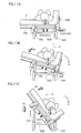
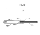
- Fig.12 shows an overall structure of a load-applying unit in embodiment 2.
- Load-applying unit 150 includes, as shown in Fig.12, a first member and a second member that are combined so as to be freely extendable/retractable, and a compression spring, a combination of the first and second members extending with increases in the slope of the platform, and the compression spring applying a load in a direction that retracts the combination of the first and second members when the slope of the platform reaches a predetermined angle.
- Load-applying unit 150 includes, specifically, a cylinder 151 (first member) and a piston 155 (second member) that plugs cylinder 151.
- a sliding member 156 that slides on the inner circumferential wall of cylinder 151 following the in/out movement of piston 155 is attached to the end of piston 155 inserted into cylinder 151, and a guiding member 152 that guides piston 155 is attached to the end of piston 155 at which piston 155 is mated.
- piston 155 can be moved in/out in an axial direction of cylinder 151, enabling load-applying unit 150 as a whole to be extended/retracted.
- a compression spring SP3 is attached at a bottom end within cylinder 151, and is constructed to resist the insertion of piston 155 when piston 155 is pushed deep within cylinder 151, by coming into contact with sliding member 156 at the end of piston 155.
- a compression spring SP2 is attached at the mating end within cylinder 151, and is constructed to resist the removal of piston 155, by coming into contact with sliding member 156.
- Load-applying units 150 on the right and left sides are attached respectively to the pairs of support arms 354R/356R and 354L/356L, so that piston 155 moves in/out with respect to cylinder 151 in accordance with the extension/retraction of elevation units 35R/35L in the up/down direction, as with the above embodiment 1. Consequently, compression spring SP3 applies a load in a direction that widens the interval between each pair of support arms 354R/356R and 354L/356L, in a state in which piston 155 is inserted into cylinder 151 so that the overall length of load-applying unit 150 is shortest. As such, it is possible to decrease the load on actuators M4R/M4L when elevation units 35R/35L begin rolling adjustable stage 20.
- a load begins to be applied to elevation units 35R/35L in a direction that resists the raising of the elevation units prior to the tilt angle of the platform reaching an angle at which the gravitational center of the platform traverses a vertical line containing the rotational center of the platform, thus making it is possible to reduce the load to actuators M4R/M4L.
- factors such as the size of the load and the position at which load-applying unit 150 begins to apply the load to elevation units 35R/35L are determined, for example, using the rotational moments during operations to tilt the platform, as well as through actual experimentation.
- the angle of the platform when load-applying unit 150 begins to apply a load to elevation units 35R/35L using compression spring SP2 is smaller than the angle at which the position acted on by the resultant of the gravitational forces of adjustable stage 20 and the care recipient traverses a vertical line C containing the rotational center, and is, for example, an angle of 30 degrees with reference to the platform in a horizontal state.
- the tilt angle of the platform when the position acted on by the resultant of the gravitational force of the care recipient traverses vertical line C containing the rotational center changes depending, for instance, on the position of the care recipient on the bed, and considering these factors (i.e. the care recipient, positioning on bed, etc.) the minimum tilt angle for use of the bed under normal conditions is 30 degrees.
- load-applying unit 150 is structured to be freely extendable by combining cylinder 151 and piston 155, if one member is moveably supported by the other member, it is possible, even with other structures, to obtain similar effects to those of embodiment 1.
- a supporting unit may be provided to support a strut at two or more places so as to be freely movable back and forth, and a compression spring that applies a load to the strut in an opposite direction to the back/forth direction of the strut may be attached to the supporting unit, this configuration being suitably determined by, for instance, the attachment position of load-applying unit 150 and the space taken up by the attachment.
- compression springs SP2 and SP3 in cylinder 151 are provided one at each end the cylinder, a plurality of springs (e.g. a fixed number of different springs) may be used at each end, and the size of the applied load varied in accordance with the tilt angle of the platform.
- the present invention is structured as a turning bed applied as an adjustable bed, in which a platform flexes (inclines) in a longitudinal direction of the bed, so as to assist the care recipient achieve sitting-up and knee-break positions.
- the platform includes an adjustable platform surface, a flex mechanism for forming a flexion position that includes at least one of a sitting-up position and a knee-break, and side-section lift mechanisms (see Fig.5) for raising the side sections of the platform relative to the middle section of the platform.
- the present invention can naturally also be applied as an adjustable bed that only rolls (tilts) the platform laterally. That is, the present invention should at least be an adjustable bed having the function of tilting the platform laterally (in the width direction of platform).
- a turning bed in which the platform surface is flexed in a longitudinal direction of the bed.
- the platform is structured from a bed frame and an adjustable stage.
- the present invention can also be applied to an adjustable bed that only tilts the platform laterally.
- an adjustable bed that only tilts the platform laterally it is also possible to provide a structure in which the adjustable stage described in embodiments 1 and 2 is eliminated, and the bed frame is tilted using a left/right pair of elevation units. Consequently, the platform in this case is the bed frame.
- load-applying units 50 and 150 are provided in elevation units (tilt mechanisms) 35R/35L, which are for tilting the platform, and a load is generated in a direction that resists the raising of the platform by elevation units 35R/35L.
- elevation units tilt mechanisms
- load-applying units may be provided in other positions.
- load-applying units may, for example, be provided respectively between guiding members 32R, 32L and bar receivers 36R, 36L, or respectively between coupling members 33R, 33L and bar receivers 36R, 36L, either vertically or obliquely.
- load-applying units may, for example, be provided respectively between support arms 354R/356R, 354L/356L and bar receivers 36R, 36L, or respectively between support arms 354R/356R, 354L/356L and guiding members 32R, 32L (coupling members 33R, 33L also possible), and a load applied in a direction that reduces the rise angle of support arms 354R/356R and 354L/356L.
- the fixed stage and adjustable stage may be directly coupled.
- the jarring motion between the adjustable stage and elevation units is eliminated when the fixed stage and adjustable stage are directly coupled, making it possible to minimize any jolting of the care recipient.
- the tilt mechanism in the above embodiment 1 is structured from elevation unit 35R/35L provided on respective sides of the platform so as to independently elevate the sides up and down, the platform being tilted by one of the elevation units raising the corresponding side of the platform.
- This procedure is not limiting, although because elevation units are provide independently on the left and right sides in embodiment 1, it is possible, for example, to combine a mechanism for adjusting the platform height, and to design for device simplification and miniaturization.
- the platform may be secured to a pivotal bearing around a fixed axis, and a predetermined part of the platform tilted by an actuator extending/retracting a rod.
- a load preferably is applied in a direction that resists the extension/retraction of the actuator rod.
- an elevation unit raises a side of the platform when the platform is tilted, although an elevation unit may, conversely, lower a side of the platform when tilting the platform.
- the load-applying unit preferably is structured to apply a load that pushes the platform up, with respect to the tension (upward direction) load exerted on the elevation unit by the platform (i.e. to apply the opposite type of load to the exerted load).
- An adjustable bed according to the present invention can be used as a nursing care bed or a reclining bed.
Abstract
Description
- The present invention relates to adjustable beds for use in nursing care and the like, and particularly to an adjustable bed having a platform that tilts toward both sides in a width direction of the bed.
- Generally, adjustable beds used as nursing-care beds (hereinafter simply "bed") include a turning mechanism to assist in the turning of care recipients in order to prevent the occurrence of decubitus ulcers, more commonly known as bedsores. This turning mechanism operates, for example, to tilt a platform surface of the bed to both the left and right sides (width direction), and turn a care recipient lying on the bed in a direction of the incline so as to assist in postural changes.
- Figs.13A to 13C show a nursing-care bed assisting the turning of a care recipient as seen from the head end of the bed. The bed given here includes, as shown in Fig.13A, a
platform 1015 having a platform surface, and afixed stage 1030 that supportsplatform 1015. Fixedstage 1030 includes asupport base 1032 on whichplatform 1015 is placed, andelevation units 1035L/1035R that elevate the left and right sides ofplatform 1015 independently. Underneathplatform 1015 is attached a left/right pair ofrollers platform 1015 resting onsupport base 1032 viaroller 1202/1203. - When, as shown in Figs.13B and 13C, one side (left side) of
platform 1015 is raised byelevation unit 1035L in a bed having this structure,roller 1202 on the other side (right side) rolls oversupport base 1032 toward the raised side (left side), andplatform 1015 tilts (rotates) in an x direction with the center ofroller 1202 as the rotational center. - However, the following problem exists with this conventional bed.
- For example, when the bed is tilted laterally to the right as shown in Fig.13B, a rotational moment M1 generated around the rotational center (i.e. center of left-side roller 1202) is anti-clockwise; that is, rotational moment M1 acts against the elevation of the side of platform 1015 (opposite of x direction in Fig.13B). As a result,
elevation unit 1035L is subject to a compression load fromplatform 1015. - Furthermore, if
platform 1015 continues to be tilted in this state, the position of a resultant W (i.e. resultant force) of the gravitational centers of the care recipient andplatform 1015 moves to the right of a vertical line C containing (i.e. passing through) the rotational center, and the rotational moment M1 around the fulcrum changes to clockwise; that is, the rotational moment M1 is reversed to act in the same direction (x direction in Fig.13C) as the elevation of the side ofplatform 1015 byelevation unit 1035L. As a result, the compression load brought to bear onelevation unit 1035L until this point changes to a tension load. - Since there is, with this adjustable bed, a slight amount of play in parts where the components are coupled to one another due to the nature of the manufacturing process, the relative positions of these coupling parts changes instantaneously when a load reversal as described above occurs, causing the operation of the adjustable bed to become intermittent, and resulting in jolting/jarring motion. Also, since the compression load on
elevation unit 1035L is suddenly removed, instantaneously releasingelevation unit 1035L from the load applied until then, the speed of the tilting operation increases momentarily, causing uneven operation. The smooth operation of the adjustable bed is compromised for these reasons, resulting in discomfort to the care recipient lying onplatform 1015. - Also, the adjustable bed given here is mostly used by elderly people in need of nursing care and people suffering serious illnesses. As such, jarring motion and variations in the tilt speed that occur during the operation of
platform 1015 may, for example, wake up a bed user who is sleeping. Since the possibility exists of stress and psychological anxiety being caused to the bed user, this area of adjustable beds is still in need of improvement. - Improving the precision of the coupling parts of the bed is one of the measures considered to date in order to prevent stress, psychological anxiety and the like being caused to bed users, although the cost hikes involved make this hardly a viable option.
- The present invention, which arose in view of the above problems, aims to provide an adjustable bed capable of tilting a platform of the bed so as not to subject a bed user to unnecessary stress.
- In order to achieve the above object, an adjustable bed pertaining the present invention includes a laterally tiltable platform; a tilt mechanism adapted to tilt the platform laterally; and a load-applying unit adapted to apply, in a state in which the platform is tilted within a predetermined angle range during operation of the tilt mechanism, a load to the platform in a direction that suppresses an expansion of the tilt angle, so as to prevent one of a compression load and a tension load exerted on the tilt mechanism by the platform from reversing to the other load type.
- Here, the predetermined angle range may include, specifically, an angle at which a gravitational center of the platform during the tilt operation traverses a vertical line containing a rotational center of the platform with the load-applying unit in a non-operational state. More specifically, the range may be from 30 degrees to 90 degrees inclusive, with reference to the platform in a horizontal state.
- Since the load on the tilt mechanism from the platform during operation is, according to these structures, maintained throughout as either a compression load or a tension load, it is possible to prevent intermittent operation of the adjustable bed. Since this construction preventing load reversals means that reversals in the load on the coupling parts do not occur with the present invention, even if, for instance, play exists structurally in the construction of the adjustable bed, particularly in the coupling parts of the tilt mechanism, it is possible to effectively prevent the jerkiness and sudden variations in speed of conventional beds during operation caused by this play. The prevent invention thus enables the bed user to feel relaxed about using the bed, without any stress or psychological anxiety being caused.
- Note that the load-applying unit may be constituted from a tension spring.
- Also, the load-applying unit may have a first member and a second member that, in combination, extend in proportion to a slope of the platform, and a compression spring disposed so as to apply a load in a direction that retracts the combination of the first and second members when the slope of the platform reaches a predetermined tilt angle, and the predetermined tilt angle may be an angle immediately prior to an angle at which a rotational moment around a rotational center that acts on the platform, reverses direction due to self weight during the operation of the tilt mechanism.
- Furthermore, the load-applying unit may include a compression spring adapted to apply, at a start of the tilting operation, a load in a direction that extends the combination of the first and second members.
- More specifically, the tilt mechanism may include an elevation unit disposed on either side of the platform, in order to elevate the platform up and down, and the platform may be tilted laterally by driving one of the elevation units.
- Also, the platform may be placed on a support base via a roller disposed on either side of the platform, and when one side of the platform is raised by the elevation unit corresponding to the side, the roller on the other side may roll over the support base toward the side being raised, and the platform may tilt with a center of the roller on the other side as a rotational center.
-
- Fig.1 is schematic view of a turning bed in an
embodiment 1; - Fig.2 is a cutaway view of part of the turning bed in
embodiment 1; - Fig.3 is a perspective view of the overall bed;
- Figs.4A & 4B are longitudinal sectional views of a bed frame and an adjustable stage;
- Figs.5A & 5B are transverse sectional views of the bed frame and the adjustable stage;
- Fig.6 is a plan view of the bed with the bed frame removed;
- Fig.7 is a perspective view of the bed with the bed frame removed;
- Fig.8 is a perspective view of the adjustable stage (elevated) and a fixed stage;
- Fig.9 is schematic view of a left-side elevation unit as seen from the inside;
- Fig.10 is a perspective view of a platform that has been rolled laterally;
- Fig.11A to 11C schematically show a rotational moment generated when the adjustable stage rolls to face right;
- Fig.12 is a sectional view of a load-applying unit in an
embodiment 2; and - Figs.13A to 13C schematically show a rotational moment generated when a platform in a conventional adjustable bed rolls to face right.
-
- Embodiments in which an adjustable bed pertaining to the present invention is applied to a turning bed are described below with reference to the drawings.
- Fig.1 is a schematic view showing a structure of a
turning bed 1 pertaining to anembodiment 1. Fig. 2 is a cutaway perspective view of a section of turningbed 1. - Turning bed 1 (hereinafter, simply "
bed 1") includes, as shown in Figs.1 and 2, amain body 2 of the bed that includes an adjustable platform surface 13 (see Fig.2), amattress 3 placed onplatform surface 13, and aremote controller 4 foroperating platform surface 13. - By operating
remote controller 4, the care recipient, for example, raises their upper body from a supine position (hereinafter, "sitting-up position"), raises their knees (hereinafter, "knee-break"), and furthermore, as shown in Fig. 1, changes their posture from a supine position to a left lateral position, for example. - Here, a posture that includes at least one of the sitting-up and knee-break positions is referred to as a "flexion position", and the tilting of
platform surface 13 ofmain body 2 in a longitudinal direction so as to obtain such a posture is referred to as "flexing"platform surface 13. - On the other hand, postural changes from a supine to a lateral position are referred to as "turning" the care recipient. In order to distinguish between the above longitudinal tilts of
platform surface 13, the tilting ofplatform surface 13 to the left or right (i.e. in a width direction of the bed) is referred to as "rolling"platform surface 13. -
Remote controller 4 is provided as operating units for flexing, elevating, and rollingplatform surface 13 ofmain body 2, when changing the position or posture of a care recipient.Remote controller 4 has a height operating unit that elevates platform surface 13 up and down to adjust the height, a head operating unit that lifts the care recipient's upper body, a leg operating unit that flexes the care recipient's knees, and a turning operating unit that turns the care recipient to the left or right. - With
main body 2,platform surface 13 flexes to assist the care recipient achieve sitting-up and knee-break positions, andplatform surface 13 also rolls to the left/right to assist the care recipient with turning from a supine to a lateral position. -
Main body 2, as shown in Fig.2, includes aninner bed frame 10 structuringadjustable platform surface 13, anadjustable stage 20 for movingbed frame 10, a fixedstage 30 that supportsadjustable stage 20, and anouter bed frame 40 that encompasses theabove components inner bed frame 10 andadjustable stage 20. - Moreover, as shown in Fig.1, when
platform surface 13 rolls to the left, for example, a section ofplatform surface 13 on the left side rises to support the care recipient from the side (left side in Fig.1), in order to prevent the care recipient from falling out ofbed 1. - Fig. 3 is a perspective view showing
main body 2 withoutouter bed frame 40. - The following description relates to the structure of
inner bed frame 10,adjustable stage 20, and fixedstage 30. -
Inner bed frame 10 is partitioned in three -middle section 11, right-side section 12R, and left-side section 12L - in a crosswise direction of bed 1 (y direction in Fig. 3; also referred to as a "latitudinal direction"), in order to, for example, flex/roll platform surface 13 as described above, and raise the side sections whenplatform surface 13 is rolled. Furthermore,sections bed 1, into four sections corresponding to the back, hip, upper leg, and lower leg regions of a care recipient's body. Note that in the present specification, the directions indicating left/right are from the viewpoint of a care recipient lying onbed 1. - With respect to
middle section 11 positioned in a middle ofbed 1 in the crosswise direction, the part corresponding to the care recipient's back is, as shown in Fig.3, referred to as aback portion 11a. Likewise, the parts corresponding to the hip, upper-leg, and lower-leg regions are referred to as ahip portion 11b, an upper-leg portion 11c, and a lower-leg portion 11d. Similarly, the parts of right-side section 12R corresponding respectively to the care recipient's back, hip, upper-leg, and lower-leg regions are referred to as a back portion 12Ra, a hip portion 12Rb, an upper-leg portion 12Rc, and a lower-leg portion 12Rd, and the parts of right-side section 12L corresponding respectively to the back, hip, upper-leg, and lower-leg regions are referred to as a back portion 12La, a hip portion 12Lb, an upper-leg portion 12Lc, and a lower-leg portion 12Ld. - Also, "
middle section 11", used hereinafter, means the entirety including backportion 11a,hip portion 11b, upper-leg portion 11c, and lower-leg portion 11d (four parts). Similarly, "right-side section 12R" means the entirety including back portion 12Ra, hip portion 12Rb, upper-leg portion 12Rc, and lower-leg portion 12Rd (four parts), while "left/right side sections 12L/R" means the entirety including back portion 12La, hip portion 12Lb, upper-leg portion 12Lc, lower-leg portion 12Ld, back portion 12Ra, hip portion 12Rb, upper-leg portion 12Rc, and lower-leg portion 12Rd (eight parts). - A wire mesh is, as shown in Fig.2, stretched across the surface (platform surface 13) of
bed frame 10, although in Fig.3, this wire mesh has been omitted so as to clearly represent the structures of other members, parts, and the like. - Figs.4A and 4B are longitudinal sectional views of
bed frame 10 andadjustable stage 20 along the A-A line in Fig. 3, Fig.4A showingbed frame 10 in a horizontal state, and Fig.4B showingbed frame 10 in a flexed state. -
Middle sections 11a-11d are, as shown in Fig.4A, supported byadjustable stage 20 with a gap therebetween (i.e. via spacers 25, for example).Hip portion 11b is fixed to spacers 26, which are secured toadjustable stage 20, by welding or the like. Bed frame is thus secured toadjustable stage 20. -
Middle sections 11a-11d are each pivotally coupled via hinges 14 to middle sections adjacent in the lengthwise direction ofbed 1. Since the axial pins ofhinges 14 are disposed in the crosswise direction (i.e. orthogonal to the page), not only do backportion 11a and upper-leg portion 11c both flex in relation tohip portion 11b, but lower-leg portion 11d flexes with the flexing of upper-leg portion 11c. - Moreover, the flexing of
back portion 11a, upper-leg portion 11c, and lower-leg portion 11d is performed by direct-acting actuators M1 and M2, which operate in accordance with button operations to the head and leg operating units ofremote controller 4. Also, in order to distinguish actuators M1/M2 from other actuators described below, actuator M1 in a vicinity of the care recipient's head is referred to as head-end actuator M1, and actuator M2 in a vicinity of the care recipient's legs is referred to as foot-end actuator M2. - Figs.5A and 5B are transverse sectional views of
bed frame 10 andadjustable stage 20 along the B-B line in Fig.3, Fig.5A showingbed frame 10 in a horizontal state, and Fig.5A showing left-side section 12L in a raised state. -
Middle sections 11a-11d are, as shown in Figs.3, 5A and 5B, pivotally coupled via hinges 15 to right/left-side sections 12Ra-12Rd and 12La-12Ld on the left and right. Since the axial pins ofhinges 15 are disposed in the lengthwise direction,side sections middle sections 11. Moreover, the raising ofside sections remote controller 4. - Fig.6 is a plan view of
main body 2 withbed frame 10 in Fig. 3 having been removed, and Fig.7 is a perspective view ofmain body 2 withbed frame 10 in Fig.3 having been removed. -
Adjustable stage 20 includes, as shown in Fig.3 and Figs.5 to 7, arectangular stage frame 21 that is long in the longitudinal direction ofbed 1, and support frames 24R/24L on the left/right that support and raise right/left side sections 12R/12L ofbed frame 10. Note that in Fig.7 depiction ofsupport frame 24L has been omitted. -
Stage frame 21, as shown in Fig.6, includes a pair oflengthwise members 21R/21L that are parallel in the longitudinal direction, and a pair ofcrosswise members 21F/21B that are coupled in the latitudinal direction to both ends of the pair oflengthwise members 21R/21L.Frame 21 is reinforced by a lengthwise reinforcingmember 21A that couples the pair ofcrosswise members 21F/21B at a substantial center betweenlengthwise members 21R/21L, and a crosswise reinforcingmember 21C that couples lengthwise reinforcingmember 21A withlengthwise members 21R/21L at the foot-end ofbed 1. - Head-end actuator M1, which has a rod coupled at one end to back
portion 11a, is, as shown also in Figs.4A and 4B, attached to a head-end of lengthwise reinforcingmember 21A.Back portion 11a, which assists the care recipient achieve a sitting-up position, is raised/lowered (flexed), as shown in Fig.4B, by extending and retracting this rod. - Also, foot-end actuator M2, which has a rod coupled at one end to back
portion 11c, is, as also shown in Figs.4A and 4B, attached to a foot-end of lengthwise reinforcingmember 21A. Upper-leg portion 11c, which assists the care recipient achieve a knee-break position, is raised/lowered (flexed), as shown in Fig.4B, by extending and retracting this rod. - Support frames 24R/24L are, as shown in Fig.3 and Figs.5 to 7, attached to
lengthwise members 21R/21L on the right and left ofstage frame 21 via coupling members 236Ra/236Rb and 236La/236Lb. - Since support frames 24R/24L have the same structure and differ only with respect to positioning (i.e. right/left), the following description relates only to support
frame 24R on the right side. Note that the reference numbers of the various members structuringleft support frame 24L are obtained by changing the "R" at the end of the reference numbers used withright support frame 24R described below to an "L". -
Support frame 24R is constituted, in a ladder-shape, from a pair oflengthwise struts struts lengthwise struts lengthwise strut 22R on the inside being pivotally supported by coupling members 236Ra/236Rb secured tolengthwise member 21R ofstage frame 21,support frame 24R is able to pivot withlengthwise strut 22R as the central axis. -
Extended parts 235R/235L, which extend downwards, are, as shown in Figs.5 and 5B, secured tolengthwise struts 22R/22L, and the rods of right/left actuators M3R/M3L, which extend and retract in the crosswise direction, are secured to theseextended parts 235R/235L. When the rods of right/left actuators M3R/M3L extend, support frames 24R/24L pivot around the axial center oflengthwise struts 22R/22L on the inside and are raised, which supports and raises right/left side sections 12R/12L from underneath. - Moreover, right/left actuators M3R/M3L are, as also shown in Figs.5A and 5B, attached to lengthwise reinforcing
member 21A and crosswise reinforcingmember 21C, and operated by the operation of operation buttons on the turning operating unit ofremote controller 4, for example. - Fixed
stage 30 is, as shown in Figs. 3 and 7, formed from asupport base 31 that supportsadjustable stage 20, and a right/left pair ofelevation units 35R/35L for elevatingadjustable stage 20 up and down, and tilting the adjustable stage to the right/left. -
Support base 31 is constituted from a pair of erection frames 32B/32F disposed one at each end in a lengthwise direction, and a pair ofcoupling members 33R/33L coupling erection frames 32B/32F in a longitudinal direction.Elevation units 35R/35L are provided on both the right and left sides ofsupport base 31 between erection frames 32B/32F.Elevation units 35R/35L on both the left and right are operated when elevatingadjustable stage 20, and one ofelevation units 35R/35L is operated when tiltingadjustable stage 20 to the left or right. - Since one of
elevation units 35R/35L raises one side ofadjustable stage 20 when rollingadjustable stage 20 to the left or right, the other side ofadjustable stage 20 needs to shift closer to side being raised. For this reason,rollers top surfaces adjustable stage 20, the rotational center (axis) whenadjustable stage 20 is tilted being a line segment connecting the centers of rollers (e.g. rollers 200/202) that roll overtop surfaces - Fig.8 is a perspective view of fixed
stage 30 withadjustable stage 20 in an elevated state, and Fig.9 is a lateral view ofelevation unit 35L from the right side. -
Elevation units 35R/35L will now be described. The following description relates toelevation unit 35L, sinceunits 35R/35L differ only in their positioning on the right and left sides. - Note that the reference numbers of the various members structuring
left elevation unit 35R are obtained by changing the "L" at the end of the reference numbers used withleft elevation unit 35L described below to an "R". -
Elevation unit 35L is, as shown in Fig.7, structured so as to receive astage bar 27L attached tolengthwise member 21L ofadjustable stage 20 from below usingbar receiver 36L.Adjustable stage 20 is raised as a result ofbar receiver 36L being raised in this state (the raising ofbar receiver 36L is also referred to as "extending" the elevation unit). - Moreover, so that stage bars 27R/27L rotate smoothly within
bar receiver 36R/36L when rollingadjustable stage 20, stage bars 27R/27L are, for example, circular in cross-section, whilebar receiver 36R/36L are correspondingly U-shaped in cross-section. - Coupled to bar
receiver 36L is, as shown Fig.8, a pair ofsupport arms 354L/356L, freely raisable/lowerable at both ends in a lengthwise direction ofbar receiver 36L, which is elevated by the up/down movement of thesesupport arms 354L/356L. Also, the lower ends ofsupport arms 354L/356L are structured to move within a guidingmember 32L in a lengthwise direction, whensupport arms 354L/356L are raised/lowered, thus enablingbar receiver 36L to be elevated in a perpendicular (up/down) direction. -
Support arms 354L/356L are pivotally coupled to the flexed part of L-shapedmembers member 32L. The ends of L-shapedmembers member 32L are coupled to ahorizontal link member 353L, and an actuator M4L is attached at an angle between thislink member 353L andbar receiver 36L. By extending/retracting the rod of actuator M4L, L-shapedmembers member 32L, and supportarms 354L/356L coupled to L-shapedmembers - So that stage bars 27R/27L do not dislodge from
bar receivers 36R/36L oncebar receivers 36R/36L have receivedstage bars 27R/27L from below, a safety mechanism that includes a belt, a chain, a spring and the like, is provided betweenstage bars 27R/27L andbar receivers 36R/36L. - On
elevation unit 35L is provided a load-applying unit 50 that applies a load in a direction that reduces the incline whenadjustable stage 20 is tilted within a range of at least 30 degrees to 90 degrees inclusive, with reference to a horizontal state of the platform, for example. This range includes an angle at which the position acted on by a resultant of the gravitation forces ofadjustable stage 20 and the care recipient traverses (i.e. crosses or passes through) a vertical line C containing the rotational center. In other words, load-applying unit 50 applies a load in a direction (downward) that reduces the lift ofbar receiver 36L included inelevation unit 35L. - The tilt angle of the platform when the position acted on by the resultant of the gravitation forces of
adjustable stage 20 and the care recipient traverses vertical line C containing the rotational center varies depending, for instance, on the care recipient's weight and position on the bed. Considering these factors that include the care recipient's weight and position, a tilt angle of 30 degrees is the smallest angle for use ofbed 1 under normal conditions. Also, in relation to the maximum angle, it is difficult to imaginebed 1 being used beyond a tilt angle of 90 degrees in terms of safety. - Specifically, load-applying unit 50 is constituted from a tension spring SP1L attached to the pair of
support arms 354L/356L. Tension spring SP1L is disposed substantially parallel to the direction in which the rod of actuator M4L extends/retracts, and applies a load onelevation units 35R/35L when the platform begins to roll. - The rod of actuator M4L is extended/retracted as a result of the height and turning operating units of
remote controller 4 being operated. -
Outer bed frame 40 is, as shown in Figs.1 and 2, constituted from aheadboard 41 disposed at the head-end ofbed 1, afootboard 42 disposed at the foot-end ofbed 1, and a left/right pair ofsideboards 43R/43L that couple headboard 41 andfootboard 42 below the sides of amattress 3.Headboard 41,footboard 42, andsideboards 43R/43L enhance the design ofbed 1, as well as preventing the bed user from being mistakenly sandwiched between the surface on whichbed 1 is established (e.g. floor) and the raisedbed frame 10, for instance. - When, with
bed 1, an operation of the height operating unit is instructed usingremote controller 4, the rods of both actuators M4R/M4L inelevation units 35R/35L extend out, and supportarms 354R/354L and 356R/356L rise up, as shown in Fig.8. As a result,bar receivers 36R/36L receivestage bars 27R/27L from below, and continue to rise up in this state. Adjustable stage 20 (platform surface 13 of bed 1) is thus raised. - On the other hand, when there is a lower operation of the height operating unit of
remote controller 4 withplatform surface 13 in a raised state, the rods of actuators M4R/M4L inelevation units 35R/35L retract, andplatform surface 13 begins to drop in height. - When, with
bed 1, an operation of the head operating unit is instructed usingremote controller 4, the rod of head-end actuator M1 extends out, and backportion 11a in the middle begins to rise in accordance with the extension of the rod, in a direction that raises the upper body, as shown in Fig.4B. At this time, back portions 12Ra/12La on the right/left ofback portion 11a, being coupled to backportion 11a via hinges 15, rise together withback portion 11a. - On the other hand, when an operation of the head operating unit is instructed using
remote controller 4 withback portions 11a/12Ra/12La in the middle and sides in a raised state, the rod of head-end actuator M1 is retracted andback portions 11a/12Ra/12La begin to return to a flat state. - When, with
bed 1, an operation of the leg operating unit is instructed usingremote controller 4, the rod of foot-end actuator M2 extends out, and upper-leg portions 11c/12Rc/12Lc in the middle and right/left sides begin to rise in accordance with the extension of the rod, which at the same time raises lower-leg portions 11d/12Rd/12Ld in the middle and right/left sides, as shown in Fig.4B. - On the other hand, when an operation of the leg operating unit of
remote controller 4 is instructed with upper-leg portions 11c/12Rc/12Lc and lower-leg portions 11d/12Rd/12Ld in the middle and sides in a raised state, the rod of foot-end actuator M2 is retracted andportions 11c/12Rc/12Lc and 11d/12Rd/12Ld begin to return to a flat state. - Described here is an exemplary operation when turning a care recipient lying supine to a left lateral position, as shown in Fig.1.
- When there is an operation of the turning operating unit of
remote controller 4, firstly, as shown in Figs.5A and 5B, the rod of left actuator M3L extends out,support frame 24L rises up around the axial center oflengthwise strut 22L on the inside, and finally, have passed through the state shown in Fig.5B,left side section 12L rises to angle of substantially 90 degrees.Side section 12L is raised in this way so as to support the left side of the care recipient whenplatform surface 13 is rolled to the left, thus preventing the care recipient from falling out ofbed 1. - Next, the rods of head and foot-end actuator M1 and M2 are extended, and the sitting-up and knee-break operations are performed. The most stable posture for a care recipient lying supine is a flexion position with knees bent and hips flexed, the above sitting-up and knee-break operations being performed to obtain this flexion position.
- Once
left side section 12L has been raised and the middle andright side sections elevation unit 35R on the right side is extended, andbar receiver 36R rises, receivingstage bar 27R. As a result,adjustable stage 20, as shown in Fig.10, begins to roll to the left. In other words, the platform is tilted by right-side elevation unit 35R, raising the right side of the platform. - Figs.11A to 11C schematically show a rotational moment that occurs when
adjustable stage 20 is rolled to face the right side, Fig.11A showingadjustable stage 20 in a horizontal state prior to rolling, Fig.11B showing a state after the rolling has started, and Fig.11C showing a state of the rolling beyond that shown in Fig.11B. - Once the rolling has started, the position acted on by resultant W of the gravitational forces of
bed frame 10,adjustable stage 20 and the care recipient is, as shown also in Fig.11B, to the left of vertical line C containing the rotational center, being the center of roller 202 (and 200). The rotational moment M1 around the rotational center resulting from resultant W acts in a downward direction (counter to x direction) on lowerselevation unit 35L. This results inelevation unit 35L being subjected to a compression load fromadjustable stage 20. -
Elevation unit 35L elevatesbar receiver 36L so that a rotational moment greater than the above rotational moment M1 acts of the rotational center. Resultant W of the gravitational forces ofbed frame 10,adjustable stage 20, and the care recipient referred to here equates of load-applying unit 50 not being attached (i.e. inactive). - Furthermore, as shown in Fig.11C, when
adjustable stage 20 is rolled, roller 202 (and 200) moves further to the left than in Fig.11B, and the position of W, which indicates the resultant of the gravitational forces ofbed frame 10,adjustable stage 20 and the care recipient, passes to the right of vertical line C containing the rotational center at the time, and the rotational moment M1 around the rotational center resulting from this resultant W acts in a direction (x direction) that pullselevation unit 35L up. - However, since tension spring SP1L attached to
elevation unit 35L applies a load P1 in a direction opposite to the direction in whichelevation unit 35L extends when W, which indicates the resultant of the gravitational forces ofadjustable stage 20 and the care recipient, traverses vertical line C containing the rotational center, compression load P1 resulting from tension spring SP1L acts onelevation unit 35L. Thus, because the compression load acts continuously from the start of the rolling, there is no operational unevenness inelevation unit 35L, even if there is up/down mechanical play inelevation unit 35L, for instance, and thus no jolting of the care recipient onbed 1. Any tendency of the operation to become intermittent is thus suppressed, enabling smooth movements to be realized. - Also, because of the compression load acting continuously on
elevation unit 35L from the start of the rolling, and a load (compression) acting constantly on actuator M4L ofelevation unit 35L in a direction that resists the tilting ofadjustable stage 20, there is no change in type of load, even if the direction of the rotation moment M1 acting onadjustable stage 20 reverses during the tilting ofadjustable stage 20. Even in this case, however, there is no operational unevenness, and no sudden changes in the rolling speed (tilt speed) ofadjustable stage 20. - With the
present embodiment 1, the provision of tension spring SP1L inelevation unit 35L means that any change in the type of load withinelevation unit 35L during the rolling of the platform (i.e. the mutual reversal of compression and tension loads) is eliminated, although load reversal does occur at parts couplingelevation unit 35L andadjustable stage 20. However, this is not actually a problem as far asbed 1 is concerned, since any jarring motion can definitely be reduced in comparison to when there is a change in the load type withinelevation unit 35L, as in the prior art. - Also, with the
present embodiment 1, tension springs SP1R/SP1L begin applying a load onelevation units 35R/35L when the platform starts to roll. Since load-applying unit 50, when rolling the platform, need only begin applying a load in a direction suppressing any expansion of the slope of the platform at a predetermined angle that includes an angle at which there is a reversal in the load exerted onelevation units 35R/35L by the platform when load-applying units 50 are inactive, the tension load may be deactivated for small tilt angles of the platform by increasing the overall length of the springs. - Furthermore, the springs need not be long if one end of the springs is to move together with the raising of
elevation units 35R/35L. In this case, however, the springs need to be constructed so that the moving end stops moving when the tilt angle of the platform reaches a predetermined angle. - Also, while the turning operation, as described above, is performed to (i) raise a side of, (ii) flex, and (iii)
roll platform surface 13, this order in not limiting. The turning operation may be performed to (i) flex, (ii) raise a side of, and (iii)roll platform surface 13, or the flexing and side-raising may be performed at the same time, after which the rolling is performed. - With the
above embodiment 1, tension springs SP1R/SP1L that apply a load when the platform starts rolling so as to reduce the slope of the platform, are used as load-applying units 50. Withembodiment 2, load-applying units 50 comprising tension springs SP1R/SP1L used inembodiment 1 is replaced by a load-applying unit that begins applying a load in a direction that suppresses the expansion of the slope of the platform when rolled, just before there is a reversal in the load exerted onelevation units 35R/35L by the platform in the case of the load-applying unit being inactive. - Fig.12 shows an overall structure of a load-applying unit in
embodiment 2. - Load-applying
unit 150 includes, as shown in Fig.12, a first member and a second member that are combined so as to be freely extendable/retractable, and a compression spring, a combination of the first and second members extending with increases in the slope of the platform, and the compression spring applying a load in a direction that retracts the combination of the first and second members when the slope of the platform reaches a predetermined angle. - Load-applying
unit 150 includes, specifically, a cylinder 151 (first member) and a piston 155 (second member) that plugscylinder 151. A slidingmember 156 that slides on the inner circumferential wall ofcylinder 151 following the in/out movement ofpiston 155 is attached to the end ofpiston 155 inserted intocylinder 151, and a guidingmember 152 that guidespiston 155 is attached to the end ofpiston 155 at whichpiston 155 is mated. As a result,piston 155 can be moved in/out in an axial direction ofcylinder 151, enabling load-applyingunit 150 as a whole to be extended/retracted. - A compression spring SP3 is attached at a bottom end within
cylinder 151, and is constructed to resist the insertion ofpiston 155 whenpiston 155 is pushed deep withincylinder 151, by coming into contact with slidingmember 156 at the end ofpiston 155. - On the other hand, a compression spring SP2 is attached at the mating end within
cylinder 151, and is constructed to resist the removal ofpiston 155, by coming into contact with slidingmember 156. - Load-applying
units 150 on the right and left sides are attached respectively to the pairs ofsupport arms 354R/356R and 354L/356L, so thatpiston 155 moves in/out with respect tocylinder 151 in accordance with the extension/retraction ofelevation units 35R/35L in the up/down direction, as with theabove embodiment 1. Consequently, compression spring SP3 applies a load in a direction that widens the interval between each pair ofsupport arms 354R/356R and 354L/356L, in a state in whichpiston 155 is inserted intocylinder 151 so that the overall length of load-applyingunit 150 is shortest. As such, it is possible to decrease the load on actuators M4R/M4L whenelevation units 35R/35L begin rollingadjustable stage 20. - On the other hand, when
piston 155 is pulled out fromcylinder 151 until just before load-applyingunit 150 reaches a maximum overall length, compression spring SP2 applies a load P1 in a direction that narrows the interval betweensupport arms 354R/356R and 354L/356L. For this reason, as shown in Fig.11C, even if rotational moment M1 around the center (rotational center) of the rollers resulting from the entire platform changes to the rolling direction, for example, there is no reversal of the load exerted onelevation units 35R/35L by adjustable stage 20 (platform). Consequently, as with theabove embodiment 1, any jolting of a care recipient lying onbed 1 is eliminated, as are sudden changes in the tilt speed during the rolling. - When load-applying
unit 150 is structured as described above, a load begins to be applied toelevation units 35R/35L in a direction that resists the raising of the elevation units prior to the tilt angle of the platform reaching an angle at which the gravitational center of the platform traverses a vertical line containing the rotational center of the platform, thus making it is possible to reduce the load to actuators M4R/M4L. - Here, factors such as the size of the load and the position at which load-applying
unit 150 begins to apply the load toelevation units 35R/35L are determined, for example, using the rotational moments during operations to tilt the platform, as well as through actual experimentation. - The angle of the platform when load-applying
unit 150 begins to apply a load toelevation units 35R/35L using compression spring SP2 is smaller than the angle at which the position acted on by the resultant of the gravitational forces ofadjustable stage 20 and the care recipient traverses a vertical line C containing the rotational center, and is, for example, an angle of 30 degrees with reference to the platform in a horizontal state. As described inembodiment 1, the tilt angle of the platform when the position acted on by the resultant of the gravitational force of the care recipient traverses vertical line C containing the rotational center changes depending, for instance, on the position of the care recipient on the bed, and considering these factors (i.e. the care recipient, positioning on bed, etc.) the minimum tilt angle for use of the bed under normal conditions is 30 degrees. - Also, although in
embodiment 2, load-applyingunit 150 is structured to be freely extendable by combiningcylinder 151 andpiston 155, if one member is moveably supported by the other member, it is possible, even with other structures, to obtain similar effects to those ofembodiment 1. For example, a supporting unit may be provided to support a strut at two or more places so as to be freely movable back and forth, and a compression spring that applies a load to the strut in an opposite direction to the back/forth direction of the strut may be attached to the supporting unit, this configuration being suitably determined by, for instance, the attachment position of load-applyingunit 150 and the space taken up by the attachment. - Furthermore, although compression springs SP2 and SP3 in
cylinder 151 are provided one at each end the cylinder, a plurality of springs (e.g. a fixed number of different springs) may be used at each end, and the size of the applied load varied in accordance with the tilt angle of the platform. - While being described above based on
embodiments - In the
above embodiments - However, the present invention can naturally also be applied as an adjustable bed that only rolls (tilts) the platform laterally. That is, the present invention should at least be an adjustable bed having the function of tilting the platform laterally (in the width direction of platform).
- In the
above embodiments embodiments - In the
above embodiments units 50 and 150 are provided in elevation units (tilt mechanisms) 35R/35L, which are for tilting the platform, and a load is generated in a direction that resists the raising of the platform byelevation units 35R/35L. However, as long as a load is applied that reduces the tilt of the platform, load-applying units may be provided in other positions. - With the structure in the
above embodiments members 32R, 32L andbar receivers coupling members bar receivers - Furthermore, load-applying units may, for example, be provided respectively between
support arms 354R/356R, 354L/356L andbar receivers support arms 354R/356R, 354L/356L and guidingmembers 32R, 32L (coupling members support arms 354R/356R and 354L/356L. - Furthermore, the fixed stage and adjustable stage may be directly coupled. In comparison to the
above embodiments - The tilt mechanism in the
above embodiment 1 is structured fromelevation unit 35R/35L provided on respective sides of the platform so as to independently elevate the sides up and down, the platform being tilted by one of the elevation units raising the corresponding side of the platform. This procedure is not limiting, although because elevation units are provide independently on the left and right sides inembodiment 1, it is possible, for example, to combine a mechanism for adjusting the platform height, and to design for device simplification and miniaturization. - For example, the platform may be secured to a pivotal bearing around a fixed axis, and a predetermined part of the platform tilted by an actuator extending/retracting a rod. In this case, a load preferably is applied in a direction that resists the extension/retraction of the actuator rod.
- Also, in the
above embodiments above embodiments - An adjustable bed according to the present invention can be used as a nursing care bed or a reclining bed.
Claims (8)
- An adjustable bed comprising:a laterally tiltable platform;a tilt mechanism adapted to tilt the platform laterally; anda load-applying unit adapted to apply, in a state in which the platform is tilted within a predetermined angle range during operation of the tilt mechanism, a load to the platform in a direction that suppresses an expansion of the tilt angle, so as to prevent one of a compression load and a tension load exerted on the tilt mechanism by the platform from reversing to the other load type.
- The adjustable bed of claim 1, wherein the predetermined angle range includes a tilt angle at which a gravitational center of the platform during the tilt operation traverses a vertical line containing a rotational center of the platform with the load-applying unit in a non-operational state.
- The adjustable bed of claim 1, wherein the predetermined angle range is from 30 degrees to 90 degrees inclusive, with reference to the platform in a horizontal state.
- The adjustable bed of claim 1, wherein the load-applying unit is constituted from a tension spring.
- The adjustable bed of claim 1, wherein
the load-applying unit has a first member and a second member that, in combination, extend in proportion to a slope of the platform, and a compression spring disposed so as to apply a load in a direction that retracts the combination of the first and second members when the slope of the platform reaches a predetermined tilt angle, and
the predetermined tilt angle is an angle immediately prior to an angle at which a rotational moment around a rotational center that acts on the platform, reverses direction due to self weight during the operation of the tilt mechanism. - The adjustable bed of claim 5, wherein the load-applying unit includes a compression spring adapted to apply, at a start of the tilting operation, a load in a direction that extends the combination of the first and second members.
- The adjustable bed of claim 1, wherein
the tilt mechanism includes an elevation unit disposed on either side of the platform, in order to elevate the platform up and down, and
the platform is tilted laterally by driving one of the elevation units. - The adjustable bed of claim 7, wherein
the platform is placed on a support base via a roller disposed on either side of the platform, and
when one side of the platform is raised by the elevation unit corresponding to the side, the roller on the other side rolls over the support base toward the side being raised, and the platform tilts with a center of the roller on the other side as a rotational center.
Applications Claiming Priority (3)
| Application Number | Priority Date | Filing Date | Title |
|---|---|---|---|
| JP2002258976 | 2002-09-04 | ||
| JP2002258976A JP3957597B2 (en) | 2002-09-04 | 2002-09-04 | Movable bed |
| PCT/JP2003/010905 WO2004021955A1 (en) | 2002-09-04 | 2003-08-28 | Movable bed |
Publications (2)
| Publication Number | Publication Date |
|---|---|
| EP1535593A1 true EP1535593A1 (en) | 2005-06-01 |
| EP1535593A4 EP1535593A4 (en) | 2006-08-30 |
Family
ID=31973049
Family Applications (1)
| Application Number | Title | Priority Date | Filing Date |
|---|---|---|---|
| EP03794110A Withdrawn EP1535593A4 (en) | 2002-09-04 | 2003-08-28 | Movable bed |
Country Status (5)
| Country | Link |
|---|---|
| US (1) | US20050166323A1 (en) |
| EP (1) | EP1535593A4 (en) |
| JP (1) | JP3957597B2 (en) |
| TW (1) | TWI230605B (en) |
| WO (1) | WO2004021955A1 (en) |
Cited By (8)
| Publication number | Priority date | Publication date | Assignee | Title |
|---|---|---|---|---|
| WO2009093125A1 (en) * | 2008-01-25 | 2009-07-30 | Nunzio Spontella | Lifting mechanism |
| NL2001550C2 (en) * | 2008-05-06 | 2009-11-12 | Cornelis Franciscus De La Haye | Adjustable spiral mattress support with pinch protection. |
| EP2308441A1 (en) * | 2008-07-31 | 2011-04-13 | Yiping Wen | Multifunctional turn-over nursing bed |
| EP2520199A1 (en) * | 2011-05-04 | 2012-11-07 | Eckhard Hansen | Seating |
| EP2760312A4 (en) * | 2011-10-02 | 2015-06-24 | Invacare Corp | Adjustable bed |
| WO2017080534A1 (en) * | 2015-11-10 | 2017-05-18 | Robotsystem, S.R.O. | Robotic mobile and modifiable bed with verticalization |
| CN111419573A (en) * | 2020-03-10 | 2020-07-17 | 西安航空学院 | Old man helps gets up device |
| WO2023035026A1 (en) * | 2021-09-08 | 2023-03-16 | Burling Aged Care Solutions Pty Ltd | A bed for turning patients |
Families Citing this family (46)
| Publication number | Priority date | Publication date | Assignee | Title |
|---|---|---|---|---|
| JP2003310668A (en) * | 2002-02-22 | 2003-11-05 | Sanyo Electric Co Ltd | Movable bed |
| AU2003296924A1 (en) * | 2002-07-24 | 2004-04-30 | France Bed Co., Ltd. | Tilting bed apparatus and mattress |
| JP3960885B2 (en) * | 2002-08-21 | 2007-08-15 | 三洋電機株式会社 | Mobile bed mat |
| FR2872030B1 (en) * | 2004-06-24 | 2006-08-25 | Centre Nat Rech Scient Cnrse | ESCARTER PREVENTION DEVICE |
| US7757318B2 (en) | 2004-09-13 | 2010-07-20 | Kreg Therapeutics, Inc. | Mattress for a hospital bed |
| US7779494B2 (en) | 2004-09-13 | 2010-08-24 | Kreg Therapeutics, Inc. | Bed having fixed length foot deck |
| US7676862B2 (en) | 2004-09-13 | 2010-03-16 | Kreg Medical, Inc. | Siderail for hospital bed |
| US7743441B2 (en) | 2004-09-13 | 2010-06-29 | Kreg Therapeutics, Inc. | Expandable width bed |
| US20070011810A1 (en) * | 2004-12-07 | 2007-01-18 | Arthur Yeager | Examination table with variable tilt |
| GB0514926D0 (en) * | 2005-07-20 | 2005-08-24 | Huntleigh Technology Plc | Bed assembly |
| US7237286B1 (en) * | 2006-01-20 | 2007-07-03 | Kim Willie W | Articulating bed |
| US20080235875A1 (en) * | 2007-03-28 | 2008-10-02 | Stryker Corporation | Maternity bed and patient lying surface therefor |
| EP2191802A4 (en) * | 2007-09-20 | 2011-05-11 | Toshihiro Niwa | Posture changing bed |
| US7845034B2 (en) * | 2007-09-21 | 2010-12-07 | Kim Willie W | Articulating bed and method of operating the same |
| US7761942B2 (en) * | 2007-10-09 | 2010-07-27 | Bedlab, Llc | Bed with adjustable patient support framework |
| US20090094745A1 (en) * | 2007-10-14 | 2009-04-16 | Eduardo Rene Benzo | Modulating Support Surface to Aid Patient Entry and Exit |
| US7716762B2 (en) * | 2007-10-14 | 2010-05-18 | Bedlab, Llc | Bed with sacral and trochanter pressure relieve functions |
| US7886379B2 (en) * | 2007-10-14 | 2011-02-15 | Bedlab, Llc | Support surface that modulates to cradle a patient's midsection |
| US9119753B2 (en) | 2008-06-27 | 2015-09-01 | Kreg Medical, Inc. | Bed with modified foot deck |
| TWI452981B (en) * | 2011-03-31 | 2014-09-21 | Univ Far East | Inclinable bed |
| KR101320168B1 (en) * | 2012-02-20 | 2013-10-23 | 전남대학교산학협력단 | Multi-functional motorized bed for immobilized bedridden patient |
| US9833368B2 (en) * | 2012-11-01 | 2017-12-05 | Hill-Rom Services, Inc. | Person support apparatus with spring assistance for articulation |
| KR20160003749A (en) * | 2013-04-25 | 2016-01-11 | 파라마운트 베드 가부시키가이샤 | Bed apparatus and bed apparatus control method |
| DE102013105413B4 (en) * | 2013-05-27 | 2018-05-09 | Logicdata Electronic & Software Entwicklungs Gmbh | Arrangement for adjusting a bed, in particular a head and foot part of the bed, and drive unit |
| WO2014201379A2 (en) * | 2013-06-15 | 2014-12-18 | Hill-Rom Services, Inc. | Adjustable person support system |
| CN105960225A (en) * | 2013-12-12 | 2016-09-21 | 皇家飞利浦有限公司 | Reformable positioning device |
| KR101576594B1 (en) | 2014-07-02 | 2015-12-10 | 조수민 | Device for preventing bedsores |
| US9724254B2 (en) * | 2014-10-03 | 2017-08-08 | Daryl L. Cole | Adjustable bed |
| ES2562263B1 (en) * | 2015-10-20 | 2016-12-07 | Tomás FERNÁNDEZ LORENZO | Dump bed for people with disabilities |
| US9933775B2 (en) | 2015-12-01 | 2018-04-03 | John A Saavedra | Programmable mattress adjustment apparatus and method |
| WO2018076248A1 (en) * | 2016-10-27 | 2018-05-03 | 上海伟赛智能科技有限公司 | Smart mattress having variable attitudes and structures |
| CN106724331B (en) * | 2016-12-30 | 2019-01-15 | 浙江世道电器有限公司 | The hanging sinking type electric in back nurses bedstead |
| US10413463B2 (en) * | 2017-03-09 | 2019-09-17 | Pablo Borges De Abreu | Hospital bed structure |
| WO2018175376A1 (en) * | 2017-03-24 | 2018-09-27 | Bedgear, Llc | Zero gravity bed |
| TWM559120U (en) * | 2018-02-01 | 2018-05-01 | Ulife Healthcare Inc | Electric furniture bed |
| US20210315754A1 (en) * | 2018-07-13 | 2021-10-14 | Umano Medical Inc. | System for adjusting a configuration of a patient support apparatus |
| CN108836601B (en) * | 2018-09-07 | 2023-08-29 | 南京林业大学 | Lumbar and cervical vertebra rehabilitation nursing bed for old people |
| CN109528405B (en) * | 2018-10-10 | 2020-09-11 | 鹤壁市人民医院 | Multifunctional movable medical nursing table structure |
| US10888171B1 (en) * | 2019-07-29 | 2021-01-12 | Gary Kinion | Tilt bed tiltable extension |
| US11622633B2 (en) * | 2019-10-08 | 2023-04-11 | Jiahuan Liu | Multifunctional motion simulation bed |
| WO2021177480A1 (en) * | 2020-03-03 | 2021-09-10 | (주)옵토닉스 | Reclining bed having independently controllable head part |
| CN112009542B (en) * | 2020-08-31 | 2022-03-11 | 中国原子能科学研究院 | Turning device |
| IT202000014263A1 (en) * | 2020-09-08 | 2022-03-08 | Marco Ceccarelli | BED WITH MOVING PARTS |
| CN112043538A (en) * | 2020-10-13 | 2020-12-08 | 北京肯搜科技有限公司 | Bidirectional vertical inclination test system |
| KR102641290B1 (en) * | 2021-04-22 | 2024-02-29 | 주식회사 아이비에스선진기업 | Bedsore preventing bed frame |
| CN114712110B (en) * | 2022-04-08 | 2023-08-22 | 林杰 | A supplementary limbs lift turnover device for surgical nursing |
Citations (5)
| Publication number | Priority date | Publication date | Assignee | Title |
|---|---|---|---|---|
| GB2233890A (en) * | 1989-05-30 | 1991-01-23 | Mediscus Prod Ltd | Therapeutic turning bed |
| US5224228A (en) * | 1992-06-17 | 1993-07-06 | Larrimore James R | Longitudinally split, motor operated butterfly bed |
| US5833291A (en) * | 1992-09-02 | 1998-11-10 | Haugs; Audun | Inflatable gripping or support device |
| US6230342B1 (en) * | 1996-02-26 | 2001-05-15 | Audun Haugs | Method and apparatus for handling of a person in a rocking movement in relation to a bed |
| US20020010960A1 (en) * | 2000-05-15 | 2002-01-31 | Friedrich Joachim W.A. | Supine position assist apparatus for adjusting the position of a person on a bed |
Family Cites Families (13)
| Publication number | Priority date | Publication date | Assignee | Title |
|---|---|---|---|---|
| GB1350915A (en) * | 1970-08-06 | 1974-04-24 | Seng K C | Beds |
| US4071916A (en) * | 1977-03-17 | 1978-02-07 | Nelson Yvette E | Apparatus for rocking a bed |
| US4152795A (en) * | 1977-12-19 | 1979-05-08 | John Rodosta | Bed rocking mechanism |
| GB2063061B (en) * | 1978-03-02 | 1982-11-17 | Gustafson H | Arrangement in beds |
| US4685159A (en) * | 1985-05-09 | 1987-08-11 | Hans Oetiker | Hospital bed |
| JPS63176434U (en) * | 1987-05-06 | 1988-11-16 | ||
| US5515561A (en) * | 1992-05-19 | 1996-05-14 | Probed Medical Technologies, Inc. | Articulating bed |
| CA2299356A1 (en) * | 1997-08-08 | 1999-02-18 | Hill-Rom, Inc. | Proning bed |
| DE10001687A1 (en) * | 2000-01-11 | 2001-07-12 | Albrecht Hoerlin | Bed for treatment of bedsores, with bed frame mounted on at least three hydraulic cylinders which can be pressurized |
| US6385801B1 (en) * | 2000-03-13 | 2002-05-14 | Kabushikikaisha Nihon M.D.M. | Rocking bed |
| CA2337994C (en) * | 2001-02-26 | 2011-07-05 | Probed Medical Technologies Inc. | Bed with adjustable positions |
| US6671905B2 (en) * | 2001-03-29 | 2004-01-06 | Kci Licensing, Inc. | Prone positioning therapeutic bed |
| US6908154B2 (en) * | 2002-12-20 | 2005-06-21 | Aono Co., Ltd. | Fold-up wheelchair and elevating apparatus of the same |
-
2002
- 2002-09-04 JP JP2002258976A patent/JP3957597B2/en not_active Expired - Fee Related
-
2003
- 2003-08-28 WO PCT/JP2003/010905 patent/WO2004021955A1/en active Application Filing
- 2003-08-28 US US10/506,420 patent/US20050166323A1/en not_active Abandoned
- 2003-08-28 EP EP03794110A patent/EP1535593A4/en not_active Withdrawn
- 2003-09-02 TW TW092124165A patent/TWI230605B/en not_active IP Right Cessation
Patent Citations (5)
| Publication number | Priority date | Publication date | Assignee | Title |
|---|---|---|---|---|
| GB2233890A (en) * | 1989-05-30 | 1991-01-23 | Mediscus Prod Ltd | Therapeutic turning bed |
| US5224228A (en) * | 1992-06-17 | 1993-07-06 | Larrimore James R | Longitudinally split, motor operated butterfly bed |
| US5833291A (en) * | 1992-09-02 | 1998-11-10 | Haugs; Audun | Inflatable gripping or support device |
| US6230342B1 (en) * | 1996-02-26 | 2001-05-15 | Audun Haugs | Method and apparatus for handling of a person in a rocking movement in relation to a bed |
| US20020010960A1 (en) * | 2000-05-15 | 2002-01-31 | Friedrich Joachim W.A. | Supine position assist apparatus for adjusting the position of a person on a bed |
Non-Patent Citations (1)
| Title |
|---|
| See also references of WO2004021955A1 * |
Cited By (11)
| Publication number | Priority date | Publication date | Assignee | Title |
|---|---|---|---|---|
| WO2009093125A1 (en) * | 2008-01-25 | 2009-07-30 | Nunzio Spontella | Lifting mechanism |
| NL2001550C2 (en) * | 2008-05-06 | 2009-11-12 | Cornelis Franciscus De La Haye | Adjustable spiral mattress support with pinch protection. |
| EP2116151A3 (en) * | 2008-05-06 | 2012-05-30 | De la Haye, Cornelis Franciscus | Adjustable spiral mattress supporting base with trapping safeguard |
| EP2308441A1 (en) * | 2008-07-31 | 2011-04-13 | Yiping Wen | Multifunctional turn-over nursing bed |
| EP2308441A4 (en) * | 2008-07-31 | 2014-11-12 | Wen Yiping | Multifunctional turn-over nursing bed |
| EP2520199A1 (en) * | 2011-05-04 | 2012-11-07 | Eckhard Hansen | Seating |
| EP2760312A4 (en) * | 2011-10-02 | 2015-06-24 | Invacare Corp | Adjustable bed |
| US9687400B2 (en) | 2011-10-02 | 2017-06-27 | Invacare Corp. | Adjustable bed |
| WO2017080534A1 (en) * | 2015-11-10 | 2017-05-18 | Robotsystem, S.R.O. | Robotic mobile and modifiable bed with verticalization |
| CN111419573A (en) * | 2020-03-10 | 2020-07-17 | 西安航空学院 | Old man helps gets up device |
| WO2023035026A1 (en) * | 2021-09-08 | 2023-03-16 | Burling Aged Care Solutions Pty Ltd | A bed for turning patients |
Also Published As
| Publication number | Publication date |
|---|---|
| JP2004097240A (en) | 2004-04-02 |
| EP1535593A4 (en) | 2006-08-30 |
| WO2004021955A1 (en) | 2004-03-18 |
| US20050166323A1 (en) | 2005-08-04 |
| TWI230605B (en) | 2005-04-11 |
| TW200403983A (en) | 2004-03-16 |
| JP3957597B2 (en) | 2007-08-15 |
Similar Documents
| Publication | Publication Date | Title |
|---|---|---|
| EP1535593A1 (en) | Movable bed | |
| US7730562B2 (en) | Patient support having powered adjustable width | |
| US8887329B2 (en) | Methods of translating hospital chair beds with articulating foot sections | |
| JP3960885B2 (en) | Mobile bed mat | |
| US6694549B2 (en) | Bed frame with reduced-shear pivot | |
| KR101227967B1 (en) | Pressure ulcer prevention for medical bed | |
| EP1541108A1 (en) | Movable bed | |
| US20190150627A1 (en) | Bed device | |
| KR101318724B1 (en) | The intelligent medical care transformable bed | |
| EP0210186A1 (en) | Mattress for beds. | |
| KR101223769B1 (en) | medical bed composed of the plural segments | |
| KR102361754B1 (en) | Electric medical bed | |
| KR20220070688A (en) | Bed robot with pressure ulcer prevention | |
| JP2008289630A (en) | Bedsore preventing bed | |
| JP3460293B2 (en) | bed | |
| JP7165969B2 (en) | Bottom mechanism for stretchers, etc. | |
| CN114795725B (en) | Nursing bed turnover mechanism and electric turnover nursing bed | |
| CN116059052B (en) | Semi-lying position adjustable large-angle side-turning nursing bed | |
| JP3575031B2 (en) | bed | |
| JP2005185736A (en) | Deformable bed | |
| JPH09299189A (en) | Bed device |
Legal Events
| Date | Code | Title | Description |
|---|---|---|---|
| PUAI | Public reference made under article 153(3) epc to a published international application that has entered the european phase |
Free format text: ORIGINAL CODE: 0009012 |
|
| 17P | Request for examination filed |
Effective date: 20041013 |
|
| AK | Designated contracting states |
Kind code of ref document: A1 Designated state(s): AT BE BG CH CY CZ DE DK EE ES FI FR GB GR HU IE IT LI LU MC NL PT RO SE SI SK TR |
|
| REG | Reference to a national code |
Ref country code: HK Ref legal event code: DE Ref document number: 1072711 Country of ref document: HK |
|
| RBV | Designated contracting states (corrected) |
Designated state(s): ES FR GB |
|
| REG | Reference to a national code |
Ref country code: DE Ref legal event code: 8566 |
|
| A4 | Supplementary search report drawn up and despatched |
Effective date: 20060801 |
|
| 17Q | First examination report despatched |
Effective date: 20061227 |
|
| STAA | Information on the status of an ep patent application or granted ep patent |
Free format text: STATUS: THE APPLICATION IS DEEMED TO BE WITHDRAWN |
|
| 18D | Application deemed to be withdrawn |
Effective date: 20090303 |
|
| REG | Reference to a national code |
Ref country code: HK Ref legal event code: WD Ref document number: 1072711 Country of ref document: HK |