EP1535564A2 - Floor cleaning machine - Google Patents
Floor cleaning machine Download PDFInfo
- Publication number
- EP1535564A2 EP1535564A2 EP04027629A EP04027629A EP1535564A2 EP 1535564 A2 EP1535564 A2 EP 1535564A2 EP 04027629 A EP04027629 A EP 04027629A EP 04027629 A EP04027629 A EP 04027629A EP 1535564 A2 EP1535564 A2 EP 1535564A2
- Authority
- EP
- European Patent Office
- Prior art keywords
- filter
- floor cleaning
- cleaning machine
- machine according
- support tube
- Prior art date
- Legal status (The legal status is an assumption and is not a legal conclusion. Google has not performed a legal analysis and makes no representation as to the accuracy of the status listed.)
- Granted
Links
- 238000004140 cleaning Methods 0.000 title claims description 57
- 230000000903 blocking effect Effects 0.000 claims description 34
- 230000033001 locomotion Effects 0.000 claims description 18
- 238000004891 communication Methods 0.000 claims description 8
- 230000008878 coupling Effects 0.000 claims description 5
- 238000010168 coupling process Methods 0.000 claims description 5
- 238000005859 coupling reaction Methods 0.000 claims description 5
- 239000012530 fluid Substances 0.000 claims description 3
- 230000002441 reversible effect Effects 0.000 claims description 2
- 230000001747 exhibiting effect Effects 0.000 claims 1
- 238000010408 sweeping Methods 0.000 description 21
- 239000000428 dust Substances 0.000 description 4
- 230000005540 biological transmission Effects 0.000 description 2
- 238000013461 design Methods 0.000 description 2
- 238000011161 development Methods 0.000 description 2
- 230000002706 hydrostatic effect Effects 0.000 description 2
- 238000000034 method Methods 0.000 description 2
- 244000007853 Sarothamnus scoparius Species 0.000 description 1
- 240000002072 Solanum torvum Species 0.000 description 1
- 235000013358 Solanum torvum Nutrition 0.000 description 1
- 230000015572 biosynthetic process Effects 0.000 description 1
- 238000007598 dipping method Methods 0.000 description 1
- 230000000694 effects Effects 0.000 description 1
- 230000002349 favourable effect Effects 0.000 description 1
- 238000012423 maintenance Methods 0.000 description 1
- 238000004519 manufacturing process Methods 0.000 description 1
- 239000000463 material Substances 0.000 description 1
- 239000002245 particle Substances 0.000 description 1
- 238000003825 pressing Methods 0.000 description 1
- 238000000926 separation method Methods 0.000 description 1
- 230000002459 sustained effect Effects 0.000 description 1
- 238000011144 upstream manufacturing Methods 0.000 description 1
- 230000037303 wrinkles Effects 0.000 description 1
Images


Classifications
-
- B—PERFORMING OPERATIONS; TRANSPORTING
- B01—PHYSICAL OR CHEMICAL PROCESSES OR APPARATUS IN GENERAL
- B01D—SEPARATION
- B01D46/00—Filters or filtering processes specially modified for separating dispersed particles from gases or vapours
- B01D46/24—Particle separators, e.g. dust precipitators, using rigid hollow filter bodies
- B01D46/2403—Particle separators, e.g. dust precipitators, using rigid hollow filter bodies characterised by the physical shape or structure of the filtering element
- B01D46/2411—Filter cartridges
-
- A—HUMAN NECESSITIES
- A47—FURNITURE; DOMESTIC ARTICLES OR APPLIANCES; COFFEE MILLS; SPICE MILLS; SUCTION CLEANERS IN GENERAL
- A47L—DOMESTIC WASHING OR CLEANING; SUCTION CLEANERS IN GENERAL
- A47L11/00—Machines for cleaning floors, carpets, furniture, walls, or wall coverings
- A47L11/24—Floor-sweeping machines, motor-driven
-
- A—HUMAN NECESSITIES
- A47—FURNITURE; DOMESTIC ARTICLES OR APPLIANCES; COFFEE MILLS; SPICE MILLS; SUCTION CLEANERS IN GENERAL
- A47L—DOMESTIC WASHING OR CLEANING; SUCTION CLEANERS IN GENERAL
- A47L11/00—Machines for cleaning floors, carpets, furniture, walls, or wall coverings
- A47L11/40—Parts or details of machines not provided for in groups A47L11/02 - A47L11/38, or not restricted to one of these groups, e.g. handles, arrangements of switches, skirts, buffers, levers
- A47L11/4027—Filtering or separating contaminants or debris
- A47L11/4033—Means for cleaning filters
-
- A—HUMAN NECESSITIES
- A47—FURNITURE; DOMESTIC ARTICLES OR APPLIANCES; COFFEE MILLS; SPICE MILLS; SUCTION CLEANERS IN GENERAL
- A47L—DOMESTIC WASHING OR CLEANING; SUCTION CLEANERS IN GENERAL
- A47L9/00—Details or accessories of suction cleaners, e.g. mechanical means for controlling the suction or for effecting pulsating action; Storing devices specially adapted to suction cleaners or parts thereof; Carrying-vehicles specially adapted for suction cleaners
- A47L9/20—Means for cleaning filters
-
- B—PERFORMING OPERATIONS; TRANSPORTING
- B01—PHYSICAL OR CHEMICAL PROCESSES OR APPARATUS IN GENERAL
- B01D—SEPARATION
- B01D46/00—Filters or filtering processes specially modified for separating dispersed particles from gases or vapours
- B01D46/52—Particle separators, e.g. dust precipitators, using filters embodying folded corrugated or wound sheet material
- B01D46/521—Particle separators, e.g. dust precipitators, using filters embodying folded corrugated or wound sheet material using folded, pleated material
-
- B—PERFORMING OPERATIONS; TRANSPORTING
- B01—PHYSICAL OR CHEMICAL PROCESSES OR APPARATUS IN GENERAL
- B01D—SEPARATION
- B01D46/00—Filters or filtering processes specially modified for separating dispersed particles from gases or vapours
- B01D46/56—Filters or filtering processes specially modified for separating dispersed particles from gases or vapours with multiple filtering elements, characterised by their mutual disposition
- B01D46/58—Filters or filtering processes specially modified for separating dispersed particles from gases or vapours with multiple filtering elements, characterised by their mutual disposition connected in parallel
- B01D46/60—Filters or filtering processes specially modified for separating dispersed particles from gases or vapours with multiple filtering elements, characterised by their mutual disposition connected in parallel arranged concentrically or coaxially
-
- B—PERFORMING OPERATIONS; TRANSPORTING
- B01—PHYSICAL OR CHEMICAL PROCESSES OR APPARATUS IN GENERAL
- B01D—SEPARATION
- B01D46/00—Filters or filtering processes specially modified for separating dispersed particles from gases or vapours
- B01D46/66—Regeneration of the filtering material or filter elements inside the filter
- B01D46/74—Regeneration of the filtering material or filter elements inside the filter by forces created by movement of the filter element
-
- E—FIXED CONSTRUCTIONS
- E01—CONSTRUCTION OF ROADS, RAILWAYS, OR BRIDGES
- E01H—STREET CLEANING; CLEANING OF PERMANENT WAYS; CLEANING BEACHES; DISPERSING OR PREVENTING FOG IN GENERAL CLEANING STREET OR RAILWAY FURNITURE OR TUNNEL WALLS
- E01H1/00—Removing undesirable matter from roads or like surfaces, with or without moistening of the surface
- E01H1/08—Pneumatically dislodging or taking-up undesirable matter or small objects; Drying by heat only or by streams of gas; Cleaning by projecting abrasive particles
- E01H1/0827—Dislodging by suction; Mechanical dislodging-cleaning apparatus with independent or dependent exhaust, e.g. dislodging-sweeping machines with independent suction nozzles ; Mechanical loosening devices working under vacuum
- E01H1/0854—Apparatus in which the mechanically dislodged dirt is partially sucked-off, e.g. dislodging- sweeping apparatus with dirt collector in brush housing or dirt container
-
- B—PERFORMING OPERATIONS; TRANSPORTING
- B01—PHYSICAL OR CHEMICAL PROCESSES OR APPARATUS IN GENERAL
- B01D—SEPARATION
- B01D2279/00—Filters adapted for separating dispersed particles from gases or vapours specially modified for specific uses
- B01D2279/55—Filters adapted for separating dispersed particles from gases or vapours specially modified for specific uses for cleaning appliances, e.g. suction cleaners
Definitions
- the invention relates to a floor cleaning machine with a dirt receptacle, the via a suction line with a suction unit in flow communication stands, wherein arranged on the suction line a pleated filter is, and with a Filterabcurisvorraum, the at least one scraper which acts on the folds of the fold filter for filter cleaning, wherein the pleated filter and the wiper relative to each other transversely to the longitudinal direction the folds are movable.
- Such floor cleaning devices come, for example, as sweeping suction machines to use, with the help of a floor surface can be cleaned.
- a sweeping roller dirt from the surface to be cleaned in be transferred to the dirt receptacle, wherein by means of the suction unit in the area of the broom and the dirt receptacle a Suction flow can be generated. This can contribute to the formation of dust
- the floor cleaning will be significantly reduced, and at the same time due to the suction flow increases the effectiveness of cleaning.
- the folded filter sets gradually with dirt particles, so that the pleated filter an increasing Flow resistance is formed for the suction flow, thereby gradually loses its effect. It is therefore necessary to fold the pleated filter to clear some operating time of the floor cleaning machine. This is it For example, from DE 37 34 355 C2, a scraper on the folds along the fold filter so that the folds are deformed by the scraper and then back to their starting position. Thereby is solved on the pleated filter adhering dirt, which is then from Dirt receptacle is added.
- Object of the present invention is to provide a floor cleaning machine of The aforementioned type in such a way that it is a structurally simpler Has design and the pleated filter are reliably cleaned can.
- the floor cleaning machine can by the first Filter area through a sustained suction flow are maintained, as long as the suction unit is in operation.
- the suction unit switched on moving the pleated filter relative to the scraper, then the first filter area cleaned by means of the scraper with continuous suction flow.
- the second filter area can be separated from the suction unit be, so that a filter cleaning of the second filter area without a suction flow acting on it can take place.
- the suction unit switched off, so both filter sections without acting on them Suction flow can be effectively cleaned by means of the scraper.
- the filter cleaning device is a blocking element for selectively enabling and interrupting the flow communication between the second filter region and the suction unit and a drive element for generating a relative movement between the scraper and the pleated filter, wherein the blocking element is coupled to the drive element is.
- a relative movement between the fold filter and the scraper are generated, and by means of Blocking element can the flow connection between the second filter area and the suction unit are interrupted.
- the operation of the Locking element can be done with the help of the drive element, which with is coupled to the blocking element.
- An additional actuator can for the blocking element omitted. Rather, it may be provided that the blocking element by means of the drive element between its release position and its interruption position is movable back and forth, for example to a Rotary axis can be set in rotation.
- the drive element can be configured, for example, as an electric motor. It is advantageous if the direction of rotation of the electric motor reversible is, because this can in a structurally simple way, a reciprocating motion the locking element between its release position and its interruption position be achieved.
- the blocking element is held against rotation on a drive shaft is, which is driven in rotation by the electric motor.
- the drive shaft can in addition to the blocking element, the pleated filter or the associated Scrapers are set in motion.
- the blocking element is designed as a rotatable diaphragm, which in a first rotational position releases an associated passage opening and in a second rotational position covering the passage opening, wherein the passage opening arranged downstream of the second filter region in the suction line is.
- the passage opening can optionally be released or covered, thereby the flow connection between the second filter area and the suction unit optionally to provide or interrupt.
- the pleated filter is a cylindrical, rotatably mounted surrounding openings and perforations supporting tube in the circumferential direction, wherein the support tube by means of the drive element about its cylinder axis is rotatable and receives the locking element.
- the support tube thus forms a Part of the suction line between the pleated filter and the suction unit and At the same time it serves to support the pleated filter by using this with its downstream side can be applied to the support tube.
- the support tube For generating a relative movement between the pleated filter and the scraper, the support tube be rotated about its cylinder axis. Within the Support tube, the blocking element is arranged. An additional space for The locking element is therefore not required, and by pressing the Locking element can structurally simple upstream of the Locking elements positioned area of the pleated filter optionally with the Suction unit brought into flow communication or separated from the suction unit become.
- the coupling elements comprise at least one stop, the interacts with a support element.
- the rotational movement of the blocking element can therefore on the stop and the support member on the support tube be transmitted.
- the stop is conveniently on the blocking element positioned and the support member may be held on the support tube.
- the stop on a Opening of the blocking element arranged.
- the breakthrough can be configured for example as a slot, which is penetrated by the support element is, wherein the longitudinal extent of the elongated hole is selected to be greater than the diameter of the support element. If the blocking element is set in rotation, so the rotational movement of the locking element on the support element transferred as soon as this to a first wall area of the slot strikes.
- the blocking element initially based on the support tube is freely rotatable and thus, for example, starting from his Release position can be transferred to its interruption position, and only with further rotational movement of the blocking element abuts the support element to the first wall portion of the elongated hole, so that then the rotational movement of the blocking element transmitted via the support member on the support tube can be. If the direction of rotation of the blocking element is reversed, then the blocking element initially turn - based on the support tube - freely rotated be returned to its release position, and only in a further rotational movement, the support member abuts a the second wall area opposite the first wall area the elongated hole, so that then a further rotational movement of the blocking element can be transferred to the support tube.
- the support element is in an advantageous embodiment as the support tube designed in the longitudinal cross-traverse.
- the traverse can on front end caps of the support tube to be held with the support tube are rigidly connected.
- a first end cap may form a lid which the support tube ends fluidly sealed while the second end cap May have openings through which the suction flow pass can.
- a filter cleaning can be carried out while the suction unit is running take place, wherein only the first filter area acted upon by the suction flow is disconnected while the second filter area from the suction flow can be.
- the first filter area without impingement To be able to clean a suction flow is in a particularly preferred Embodiment provided that the pleated filter when turned off Suction unit is movable relative to the wiper.
- the pleated filter after switching off the Suction unit is automatically movable relative to the wiper. This will the handling of the floor cleaning machine considerably simplified, because after completion of the floor cleaning, the user only needs the suction unit switch off, and then can automatically filter cleaning be carried out without a portion of the pleated filter with suction flow is charged.
- the floor cleaning machine according to the invention is preferably as a mobile Sweeping machine configured and includes a sweeping roller, the Dirt receptacle is arranged adjacent.
- FIG. 1 schematically shows a floor cleaning machine according to the invention in FIG Form of a total occupied by the reference numeral 10 mobile sweeping suction machine represented, with the aid of a bottom surface 12 are cleaned can.
- It comprises a drive 14, the top side a battery box 15 carries, which receives a battery for powering the sweeping suction machine.
- a seat 16 is held, on which the user in the process of sweeping suction machine 10 can take place.
- the drive of the sweeping suction machine 10 is carried out with the aid of a hydraulic unit 17, with an electric pump not shown in the drawing is coupled and positioned with a behind the battery box 15 Hydrostatic transmission 18 is in operative connection.
- front wheels 20 and rear wheels 21 are held on the underside of the chassis 14 .
- the front wheels 20 are in front of the seat 16 in the direction of travel 19 arranged steering wheel 23 coupled.
- Between the front and rear wheels 20, 21 is underside of the chassis 14 lowered onto the bottom surface 12 and held by this liftable sweeping roller 25, which is a transversely to the Direction of travel 19 aligned roller axis 26 is rotationally driven and with whose help the floor area can be swept.
- In direction of travel 19 before the Sweeping roller 25 is a rough dirt flap 28 on the underside of the chassis 14 positioned, and behind the sweeping roller 25 is a dirt receptacle 30, in which the recorded by the sweeping roller 25 Sweeping material 32 can be transferred.
- the inclusion of the debris in the dirt receptacle 30 is of a Suction flow 34 supported by one above the hydrostatic transmission 18 arranged suction unit 36 is generated, which via a suction channel 38 in fluid communication with the dirt receptacle 30 stands.
- the suction channel 38 is on a longitudinal side of the sweeping suction machine 10 on Chassis 14 fixed and is aligned across a direction transverse to the direction 19 Support tube 40 with the dirt receptacle 30 in flow communication.
- the support tube 40 is cylindrical and can by means of a drive element in the form of an electric motor 43 about its cylinder axis 41 are rotated.
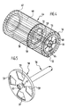
- the support tube 40 has over its entire length and its entire circumference a plurality of openings 42. In the figures 2 and 3 are to achieve a better overview of these breakthroughs 42 only partially shown.
- In the circumferential direction is the Support tube 40 surrounded by a star-shaped folded pleated filter 44, through that the suction flow 34 is passed.
- the sweeping suction machine 10 comprises upwardly projecting arms 46, at which a transverse to the direction of travel 19 aligned pivot axis 47th pivotable pivot arms 48 are held, which the dirt receptacle 30 laterally between them.
- the dirt receptacle in a solid line in lowered, immediately behind the Sweeping roller 25 positioned position shown, and in dashed line the dirt receptacle 30 illustrated in its raised position.
- the suction flow 34 is in the radial direction through the Pleated filter 44 passes, then flows transversely to the direction of travel 19 along the support tube 40 and is of this - in Figures 2 and 3 on the right side - passed to the suction channel 38, from which the suction flow 44 is forwarded to the suction unit 36.
- the support tube 40 forms Thus, in combination with the suction channel 38, a suction line, via which the Dirt receptacle 30 with the suction unit 36 in fluid communication stands.
- the support tube 40 and held on it Pleated filter 44 by means of the electric motor 43 about the cylinder axis 41 in Rotation are offset so that the pleated filter 44 related relative movement performs on the scraper 52, wherein the flexibly formed folds 54 are deflected from the scraper 52 from its original position and then snap back into this, so that adhering to the folds 54 Dirt is detached and falls into the dirt receptacle 30.
- the rotary drive of the support tube 40 is carried by the electric motor 43 via a coaxial aligned to the support tube 40 and received by this drive shaft 56, which is about a known and therefore in the drawing not shown gear is coupled to the electric motor 43 and at their in the support tube 40 dipping end of a blocking element in the form of a first aperture 58 carries.
- the first Shutter 58 has four evenly distributed over its circumference Openings 59 and is held against rotation on the drive shaft 56.
- the first aperture 58 has two diametrically opposed ones Longitudinal bores 61, 62, in the direction of rotation of the drive shaft 56th are aligned.
- the longitudinal bores 61, 62 are each of a traverse 64 and 65, which are parallel to the cylinder axis 41 of the support tube 40 aligned and fixed to end-side end caps 67, 68 of the support tube 40 are.
- the end cap 67 is on the drive shaft 56 opposite end face arranged the support tube 40 and forms the support tube 40 frontally flow-tight closing lid.
- the End cap 68 which is penetrated by the drive shaft 56, a plurality of outlet openings 70, through which the suction flow 34 can pass.
- a second aperture 70 is set, the first Aperture 58 is disposed immediately adjacent and by means of a support sleeve 71 is supported on the drive shaft 56. With a rotary movement of the drive shaft 56, the support sleeve 71 on the outer circumference of the drive shaft 56th glide along.
- the second panel 70 has corresponding to the first panel 58th Openings 72, depending on the rotational position of the drive shaft 56th fixed first aperture 58 with the openings 59 of the first panel 58 can be brought to coincidence, as shown in Figure 2, or in the direction of rotation of the drive shaft 56 offset to the openings 59 of the first aperture 58 can be positioned so that the first Aperture 58 covers the apertures 72 of the second aperture 70, as shown in FIG Figure 3 is illustrated.
- the drive shaft 56 and fixed to her first aperture 58 about the cylinder axis 41 rotated. This can due to the longitudinal extent of the Longitudinal bores 61 and 62, the first aperture 58 relative to the second aperture 70th are first rotated in a rotational position in which the openings 72nd the second aperture 70 are covered by the first aperture 58.
- the truss 64 and 65 respectively to one end side of the longitudinal bores 61 and 62, so that the rotational movement the drive shaft 56 via the first panel 58 and the trusses 64, 65 transmitted to the support tube 40 and held on this folded filter 44 becomes.
- the pleated filter 44 thus performs a rotational movement, so that the Wrinkles 54 are reliably cleaned by the scraper 52.
- the openings 72 of the second aperture 70 of the first Aperture 58 are covered during the filter cleaning only one first filter area, namely between the end cap 68 and the first Aperture 58 arranged region 74 of the pleated filter 44, from the suction flow flows through, while a second filter area 75, namely the area of Pleated filter 44 disposed between the first panel 58 and the end cap 67 is separated from the suction flow 34. This is shown in FIG.
- this filter area can be particularly effective at the same time due to the maintenance of the Suction flow 34 is ensured through the first filter region 74, that during the filter cleaning a dirt receptacle 30th thorough suction flow is maintained to avoid Dust development during filter cleaning.
Landscapes
- Chemical Kinetics & Catalysis (AREA)
- Chemical & Material Sciences (AREA)
- Engineering & Computer Science (AREA)
- Structural Engineering (AREA)
- Mechanical Engineering (AREA)
- Architecture (AREA)
- Civil Engineering (AREA)
- Physics & Mathematics (AREA)
- Geometry (AREA)
- Filtering Of Dispersed Particles In Gases (AREA)
- Vehicle Cleaning, Maintenance, Repair, Refitting, And Outriggers (AREA)
- Pinball Game Machines (AREA)
- Nozzles For Electric Vacuum Cleaners (AREA)
- Working Measures On Existing Buildindgs (AREA)
- Filters For Electric Vacuum Cleaners (AREA)
- Cleaning In General (AREA)
- Air Filters, Heat-Exchange Apparatuses, And Housings Of Air-Conditioning Units (AREA)
Abstract
Description
Die Erfindung betrifft eine Bodenreinigungsmaschine mit einem Schmutzaufnahmebehälter, der über eine Saugleitung mit einem Saugaggregat in Strömungsverbindung steht, wobei an der Saugleitung ein Faltenfilter angeordnet ist, und mit einer Filterabreinigungsvorrichtung, die mindestens einen Abstreifer aufweist, der zur Filterabreinigung an den Falten des Faltenfilters angreift, wobei das Faltenfilter und der Abstreifer relativ zueinander quer zur Längsrichtung der Falten bewegbar sind.The invention relates to a floor cleaning machine with a dirt receptacle, the via a suction line with a suction unit in flow communication stands, wherein arranged on the suction line a pleated filter is, and with a Filterabreinigungsvorrichtung, the at least one scraper which acts on the folds of the fold filter for filter cleaning, wherein the pleated filter and the wiper relative to each other transversely to the longitudinal direction the folds are movable.
Derartige Bodenreinigungsgeräte kommen beispielsweise als Kehr-Saugmaschinen zum Einsatz, mit deren Hilfe eine Bodenfläche gereinigt werden kann. Mittels einer Kehrwalze kann Schmutz von der zu reinigenden Bodenfläche in den Schmutzaufnahmebehälter überführt werden, wobei mittels des Saugaggregates im Bereich der Kehrwalze und des Schmutzaufnahmebehälters eine Saugströmung erzeugt werden kann. Dadurch kann die Staubentwicklung bei der Bodenreinigung erheblich vermindert werden, und gleichzeitig wird aufgrund der Saugströmung die Effektivität der Reinigung erhöht.Such floor cleaning devices come, for example, as sweeping suction machines to use, with the help of a floor surface can be cleaned. By means of a sweeping roller dirt from the surface to be cleaned in be transferred to the dirt receptacle, wherein by means of the suction unit in the area of the broom and the dirt receptacle a Suction flow can be generated. This can contribute to the formation of dust The floor cleaning will be significantly reduced, and at the same time due to the suction flow increases the effectiveness of cleaning.
Während des Betriebes der Bodenreinigungsmaschine setzt sich das Faltenfilter allmählich mit Schmutzpartikeln zu, so daß das Faltenfilter einen zunehmenden Strömungswiderstand für die Saugströmung ausbildet, die dadurch allmählich an Wirkung verliert. Es ist deshalb erforderlich, das Faltenfilter nach einiger Betriebszeit der Bodenreinigungsmaschine abzureinigen. Hierzu ist es beispielsweise aus der DE 37 34 355 C2 bekannt, einen Abstreifer an den Falten des Faltenfilters entlang zu führen, so daß die Falten vom Abstreifer verformt werden und anschließend in ihre Ausgangslage zurückschnellen. Dadurch wird am Faltenfilter anhaftender Schmutz gelöst, der anschließend vom Schmutzaufnahmebehälter aufgenommen wird.During operation of the floor cleaning machine, the folded filter sets gradually with dirt particles, so that the pleated filter an increasing Flow resistance is formed for the suction flow, thereby gradually loses its effect. It is therefore necessary to fold the pleated filter to clear some operating time of the floor cleaning machine. This is it For example, from DE 37 34 355 C2, a scraper on the folds along the fold filter so that the folds are deformed by the scraper and then back to their starting position. Thereby is solved on the pleated filter adhering dirt, which is then from Dirt receptacle is added.
In der EP 0 793 988 wird eine Bodenreinigungsmaschine der eingangs genannten Art beschrieben, bei der ein hohlzylinderförmiges Faltenfilter zum Einsatz kommt, das zur Filterabreinigung manuell oder elektromotorisch um seine Zylinderachse in Drehung versetzt werden kann, während der Abstreifer im Schmutzaufnahmebehälter fixiert ist. Zur Filterabreinigung wird das Saugaggregat abgeschaltet, so daß das Faltenfilter keiner Saugströmung unterliegt. Dies hat eine wirkungsvolle Filterabreinigung zur Folge, es ist allerdings nachteilig, daß während der Filterabreinigung die Bodenreinigungsmaschine nicht zur Bodenreinigung eingesetzt werden kann, denn bei ausgeschaltetem Saugaggregat wäre der Betrieb der Bodenreinigungsmaschine mit einer starken Staubentwicklung verbunden. In der EP 0 793 988 A2 wird deshalb ergänzend vorgeschlagen, zwei Faltenfilter innerhalb des Schmutzaufnahmebehälters drehbar zu lagern, wobei die Saugströmung alternativ durch eines der beiden Faltenfilter hindurchgeführt wird. Somit kann eines der beiden Faltenfilter wirkungsvoll abgereinigt werden, ohne daß es einer Saugströmung unterliegt, während das andere Faltenfilter zur Schmutzabscheidung zum Einsatz kommt. Hierzu sind allerdings zwei in Strömungsrichtung parallel geschaltete Faltenfilter erforderlich, denen jeweils ein Drehantrieb sowie eine die Strömungsverbindung zum Saugaggregat wahlweise freigebende und unterbrechende Schließklappe zugeordnet ist. Dies hat einen konstruktiv aufwendigen Aufbau der Bodenreinigungsmaschine zur Folge und erhöht deren Herstellungskosten.In EP 0 793 988 a floor cleaning machine of the aforementioned Art described in which a hollow cylindrical pleated filter used comes to filter cleaning manually or by electric motor to his Cylinder axis can be rotated while the scraper in Dirt receptacle is fixed. For filter cleaning, the suction unit switched off, so that the pleated filter is not subject to suction flow. This results in an effective filter cleaning, but it is disadvantageous that during the filter cleaning the floor cleaning machine not can be used for floor cleaning, because with the suction unit off would be the operation of the floor cleaning machine with a strong Dust associated. In EP 0 793 988 A2 is therefore supplementary proposed, two pleated filters within the dirt receptacle rotatably support, wherein the suction flow alternatively by one of the two Wrinkled filter is passed. Thus, one of the two folded filters be effectively cleaned without being subject to a suction flow, while the other pleated filter is used for dirt separation. For this purpose, however, two parallel in the flow direction connected pleated filter required, each with a rotary drive and a flow connection to the suction unit optionally releasing and interrupting Closing flap is assigned. This has a structurally complex structure the floor cleaning machine result and increases their production costs.
Aufgabe der vorliegenden Erfindung ist es, eine Bodenreinigungsmaschine der eingangs genannten Art derart weiterzubilden, daß sie eine konstruktiv einfachere Ausgestaltung aufweist und das Faltenfilter zuverlässig abgereinigt werden kann.Object of the present invention is to provide a floor cleaning machine of The aforementioned type in such a way that it is a structurally simpler Has design and the pleated filter are reliably cleaned can.
Diese Aufgabe wird bei einer Bodenreinigungsmaschine der gattungsgemäßen Art erfindungsgemäß dadurch gelöst, daß das Faltenfilter einen ersten und einen zweiten Filterbereich umfaßt, wobei der erste Filterbereich permanent mit dem Saugaggregat in Strömungsverbindung steht, und wobei die Strömungsverbindung zwischen dem zweiten Filterbereich und dem Saugaggregat wahlweise freigebbar und unterbrechbar ist.This object is achieved in a floor cleaning machine of the generic type Art according to the invention solved in that the pleated filter a first and a second filter area, wherein the first filter area permanently with the suction unit is in flow communication, and wherein the flow connection between the second filter area and the suction unit optionally is releasable and interruptible.
Bei der erfindungsgemäßen Bodenreinigungsmaschine kann durch den ersten Filterbereich hindurch eine andauernde Saugströmung aufrechterhalten werden, solange das Saugaggregat in Betrieb ist. Wird bei eingeschaltetem Saugaggregat das Faltenfilter relativ zum Abstreifer bewegt, so wird der erste Filterbereich mittels des Abstreifers abgereinigt bei andauernder Saugströmung. Im Gegensatz hierzu kann der zweite Filterbereich vom Saugaggregat abgetrennt werden, so daß eine Filterabreinigung des zweiten Filterbereiches ohne eine auf ihn einwirkende Saugströmung erfolgen kann. Wird das Saugaggregat ausgeschaltet, so können beide Filterteilbereiche ohne auf sie einwirkende Saugströmung mittels des Abstreifers wirkungsvoll abgereinigt werden.In the floor cleaning machine according to the invention can by the first Filter area through a sustained suction flow are maintained, as long as the suction unit is in operation. With the suction unit switched on moving the pleated filter relative to the scraper, then the first filter area cleaned by means of the scraper with continuous suction flow. In contrast, the second filter area can be separated from the suction unit be, so that a filter cleaning of the second filter area without a suction flow acting on it can take place. Will the suction unit switched off, so both filter sections without acting on them Suction flow can be effectively cleaned by means of the scraper.
Von Vorteil ist es, wenn die Filterabreinigungsvorrichtung ein Sperrelement zum wahlweisen Freigeben und Unterbrechen der Strömungsverbindung zwischen dem zweiten Filterbereich und dem Saugaggregat umfaßt sowie ein Antriebselement zum Erzeugen einer Relativbewegung zwischen dem Abstreifer und dem Faltenfilter, wobei das Sperrelement mit dem Antriebselement gekoppelt ist. Mittels des Antriebselementes kann eine Relativbewegung zwischen dem Faltenfilter und dem Abstreifer erzeugt werden, und mittels des Sperrelementes kann die Strömungsverbindung zwischen dem zweiten Filterbereich und dem Saugaggregat unterbrochen werden. Die Betätigung des Sperrelementes kann hierbei mit Hilfe des Antriebselementes erfolgen, das mit dem Sperrelement gekoppelt ist. Ein zusätzliches Betätigungsorgan kann für das Sperrelement entfallen. Es kann vielmehr vorgesehen sein, daß das Sperrelement mittels des Antriebselementes zwischen seiner Freigabestellung und seiner Unterbrechungsstellung hin und her bewegbar ist, zum Beispiel um eine Drehachse in Drehung versetzt werden kann.It is advantageous if the filter cleaning device is a blocking element for selectively enabling and interrupting the flow communication between the second filter region and the suction unit and a drive element for generating a relative movement between the scraper and the pleated filter, wherein the blocking element is coupled to the drive element is. By means of the drive element, a relative movement between the fold filter and the scraper are generated, and by means of Blocking element can the flow connection between the second filter area and the suction unit are interrupted. The operation of the Locking element can be done with the help of the drive element, which with is coupled to the blocking element. An additional actuator can for the blocking element omitted. Rather, it may be provided that the blocking element by means of the drive element between its release position and its interruption position is movable back and forth, for example to a Rotary axis can be set in rotation.
Das Antriebselement kann beispielsweise als Elektromotor ausgestaltet sein. Hierbei ist es von Vorteil, wenn die Drehrichtung des Elektromotors umkehrbar ist, denn dadurch kann auf konstruktiv einfache Weise eine Hin- und Herbewegung des Sperrelementes zwischen seiner Freigabestellung und seiner Unterbrechungsstellung erzielt werden.The drive element can be configured, for example, as an electric motor. It is advantageous if the direction of rotation of the electric motor reversible is, because this can in a structurally simple way, a reciprocating motion the locking element between its release position and its interruption position be achieved.
Günstig ist es, wenn das Sperrelement drehfest an einer Antriebswelle gehalten ist, die vom Elektromotor drehend antreibbar ist. Mittels der Antriebswelle kann zusätzlich zum Sperrelement auch das Faltenfilter oder der zugeordnete Abstreifer in Bewegung versetzt werden.It is favorable if the blocking element is held against rotation on a drive shaft is, which is driven in rotation by the electric motor. By means of the drive shaft can in addition to the blocking element, the pleated filter or the associated Scrapers are set in motion.
Bei einer bevorzugten Ausgestaltung der erfindungsgemäßen Bodenreinigungsmaschine ist das Sperrelement als drehbare Blende ausgestaltet, die in einer ersten Drehstellung eine zugeordnete Durchlaßöffnung freigibt und in einer zweiten Drehstellung die Durchlaßöffnung abdeckt, wobei die Durchlaßöffnung stromabwärts des zweiten Filterbereiches in der Saugleitung angeordnet ist. Mittels des drehbaren Sperrelementes kann die Durchlaßöffnung wahlweise freigegeben oder abgedeckt werden, um dadurch die Strömungsverbindung zwischen dem zweiten Filterbereich und dem Saugaggregat wahlweise bereitzustellen oder zu unterbrechen.In a preferred embodiment of the floor cleaning machine according to the invention the blocking element is designed as a rotatable diaphragm, which in a first rotational position releases an associated passage opening and in a second rotational position covering the passage opening, wherein the passage opening arranged downstream of the second filter region in the suction line is. By means of the rotatable blocking element, the passage opening can optionally be released or covered, thereby the flow connection between the second filter area and the suction unit optionally to provide or interrupt.
Günstig ist es, wenn das Faltenfilter ein zylinderförmiges, drehbar gelagertes und Durchbrechungen aufweisendes Stützrohr in Umfangsrichtung umgibt, wobei das Stützrohr mittels des Antriebselementes um seine Zylinderachse drehbar ist und das Sperrelement aufnimmt. Das Stützrohr bildet somit einen Teil der Saugleitung zwischen dem Faltenfilter und dem Saugaggregat und dient gleichzeitig der Abstützung des Faltenfilters, indem dieses mit seiner stromabwärtigen Seite an das Stützrohr anlegbar ist. Zur Erzeugung einer Relativbewegung zwischen dem Faltenfilter und dem Abstreifer kann das Stützrohr um seine Zylinderachse in Drehung versetzt werden. Innerhalb des Stützrohres ist das Sperrelement angeordnet. Ein zusätzlicher Bauraum für das Sperrelement ist folglich nicht erforderlich, und durch Betätigung des Sperrelementes kann auf konstruktiv einfache Weise der stromaufwärts des Sperrelements positionierte Bereich des Faltenfilters wahlweise mit dem Saugaggregat in Strömungsverbindung gebracht oder vom Saugaggregat abgetrennt werden.It is advantageous if the pleated filter is a cylindrical, rotatably mounted surrounding openings and perforations supporting tube in the circumferential direction, wherein the support tube by means of the drive element about its cylinder axis is rotatable and receives the locking element. The support tube thus forms a Part of the suction line between the pleated filter and the suction unit and At the same time it serves to support the pleated filter by using this with its downstream side can be applied to the support tube. For generating a relative movement between the pleated filter and the scraper, the support tube be rotated about its cylinder axis. Within the Support tube, the blocking element is arranged. An additional space for The locking element is therefore not required, and by pressing the Locking element can structurally simple upstream of the Locking elements positioned area of the pleated filter optionally with the Suction unit brought into flow communication or separated from the suction unit become.
Von besonderem Vorteil im Hinblick auf eine kompakte Ausgestaltung der Bodenreinigungsmaschine ist es, wenn das Sperrelement drehfest an einer um die Zylinderachse des Stützrohres drehbaren Antriebswelle gehalten ist, die in das Stützrohr eintaucht, wobei das Sperrelement über Kopplungselemente mit dem Stützrohr gekoppelt ist. Dies gibt die Möglichkeit, die Antriebswelle mittels des Antriebselementes in Drehung zu versetzen, so daß das Sperrelement um die Zylinderachse des Stützrohres gedreht und zwischen seiner Freigabestellung und seiner Unterbrechungsstellung hin und her bewegt werden kann, und die Drehbewegung des Sperrelementes kann über die Kopplungselemente auf das Stützrohr übertragen werden, so daß auch das Stützrohr und mit diesem das an ihm anliegende Faltenfilter zur Filterabreinigung in Drehung versetzt werden können.Of particular advantage in view of a compact design of the floor cleaning machine it is when the blocking element rotatably on a order the cylinder axis of the support tube is held rotatable drive shaft, which in the support tube is immersed, wherein the blocking element via coupling elements with coupled to the support tube. This gives the possibility of using the drive shaft of the drive element in rotation, so that the blocking element to rotated the cylinder axis of the support tube and between its release position and its interruption position can be moved back and forth, and the rotational movement of the blocking element can via the coupling elements the support tube are transmitted, so that the support tube and with this put the fitting to him folded filter for filter cleaning in rotation can be.
Vorzugsweise umfassen die Kopplungselemente zumindest einen Anschlag, der mit einem Stützelement zusammenwirkt. Die Drehbewegung des Sperrelementes kann folglich über den Anschlag und das Stützelement auf das Stützrohr übertragen werden. Der Anschlag ist günstigerweise am Sperrelement positioniert und das Stützelement kann am Stützrohr gehalten sein.Preferably, the coupling elements comprise at least one stop, the interacts with a support element. The rotational movement of the blocking element can therefore on the stop and the support member on the support tube be transmitted. The stop is conveniently on the blocking element positioned and the support member may be held on the support tube.
Bei einer bevorzugten Ausführungsform der Erfindung ist der Anschlag an einer Durchbrechung des Sperrelementes angeordnet. Die Durchbrechung kann beispielsweise als Langloch ausgestaltet sein, das vom Stützelement durchgriffen ist, wobei die Längserstreckung des Langloches größer gewählt ist als der Durchmesser des Stützelementes. Wird das Sperrelement in Drehung versetzt, so wird die Drehbewegung des Sperrelementes auf das Stützelement übertragen, sobald dieses an einen ersten Wandungsbereich des Langloches anschlägt. Dies hat den Vorteil, daß das Sperrelement zunächst bezogen auf das Stützrohr frei drehbar ist und damit beispielsweise ausgehend von seiner Freigabestellung in seine Unterbrechungsstellung überführt werden kann, und erst bei weiterer Drehbewegung des Sperrelementes stößt das Stützelement an den ersten Wandungsbereich des Langloches, so daß dann die Drehbewegung des Sperrelementes über das Stützelement auf das Stützrohr übertragen werden kann. Wird die Drehrichtung des Sperrelementes umgekehrt, so kann das Sperrelement anfänglich wiederum - bezogen auf das Stützrohr - frei gedreht werden und somit wieder in seine Freigabestellung überführt werden, und erst bei einer weiteren Drehbewegung stößt das Stützelement an einer dem ersten Wandungsbereich gegenüberliegenden zweiten Wandungsbereich des Langloches, so daß dann eine weitere Drehbewegung des Sperrelementes auf das Stützrohr übertragen werden kann.In a preferred embodiment of the invention, the stop on a Opening of the blocking element arranged. The breakthrough can be configured for example as a slot, which is penetrated by the support element is, wherein the longitudinal extent of the elongated hole is selected to be greater than the diameter of the support element. If the blocking element is set in rotation, so the rotational movement of the locking element on the support element transferred as soon as this to a first wall area of the slot strikes. This has the advantage that the blocking element initially based on the support tube is freely rotatable and thus, for example, starting from his Release position can be transferred to its interruption position, and only with further rotational movement of the blocking element abuts the support element to the first wall portion of the elongated hole, so that then the rotational movement of the blocking element transmitted via the support member on the support tube can be. If the direction of rotation of the blocking element is reversed, then the blocking element initially turn - based on the support tube - freely rotated be returned to its release position, and only in a further rotational movement, the support member abuts a the second wall area opposite the first wall area the elongated hole, so that then a further rotational movement of the blocking element can be transferred to the support tube.
Das Stützelement ist bei einer vorteilhaften Ausführungsform als das Stützrohr in Längsrichtung durchgreifende Traverse ausgestaltet. Die Traverse kann an stirnseitigen Endkappen des Stützrohres gehalten sein, die mit dem Stützrohr starr verbunden sind. Eine erste Endkappe kann einen Deckel ausbilden, der das Stützrohr endseitig strömungsdicht abschließt, während die zweite Endkappe Öffnungen aufweisen kann, durch die die Saugströmung hindurchtreten kann.The support element is in an advantageous embodiment as the support tube designed in the longitudinal cross-traverse. The traverse can on front end caps of the support tube to be held with the support tube are rigidly connected. A first end cap may form a lid which the support tube ends fluidly sealed while the second end cap May have openings through which the suction flow pass can.
Wie bereits erläutert, kann bei laufendem Saugaggregat eine Filterabreinigung erfolgen, wobei lediglich der erste Filterbereich von der Saugströmung beaufschlagt wird, während der zweite Filterbereich von der Saugströmung abgekoppelt werden kann. Um auch den ersten Filterbereich ohne Beaufschlagung einer Saugströmung abreinigen zu können, ist bei einer besonders bevorzugten Ausführungsform vorgesehen, daß das Faltenfilter bei ausgeschaltetem Saugaggregat relativ zum Abstreifer bewegbar ist.As already explained, a filter cleaning can be carried out while the suction unit is running take place, wherein only the first filter area acted upon by the suction flow is disconnected while the second filter area from the suction flow can be. To also the first filter area without impingement To be able to clean a suction flow is in a particularly preferred Embodiment provided that the pleated filter when turned off Suction unit is movable relative to the wiper.
Hierbei ist es von Vorteil, wenn das Faltenfilter nach dem Ausschalten des Saugaggregates selbsttätig relativ zum Abstreifer bewegbar ist. Dadurch wird die Handhabung der Bodenreinigungsmaschine erheblich vereinfacht, denn nach Beendigung der Bodenreinigung muß der Benutzer lediglich das Saugaggregat abschalten, und anschließend kann selbsttätig eine Filterabreinigung durchgeführt werden, ohne daß ein Bereich des Faltenfilters mit Saugströmung beaufschlagt wird.It is advantageous if the pleated filter after switching off the Suction unit is automatically movable relative to the wiper. This will the handling of the floor cleaning machine considerably simplified, because after completion of the floor cleaning, the user only needs the suction unit switch off, and then can automatically filter cleaning be carried out without a portion of the pleated filter with suction flow is charged.
Die erfindungsgemäße Bodenreinigungsmaschine ist vorzugsweise als fahrbare Kehr-Saugmaschine ausgestaltet und umfaßt eine Kehrwalze, die dem Schmutzaufnahmebehälter benachbart angeordnet ist.The floor cleaning machine according to the invention is preferably as a mobile Sweeping machine configured and includes a sweeping roller, the Dirt receptacle is arranged adjacent.
Die nachfolgende Beschreibung einer bevorzugten Ausführungsform der Erfindung dient im Zusammenhang mit der Zeichnung der näheren Erläuterung. Es zeigen:
- Figur 1:
- eine schematische Darstellung einer erfindungsgemäßen Bodenreinigungsmaschine;
- Figur 2:
- eine Schnittansicht eines Faltenfilters der Bodenreinigungsmaschine mit einem ersten und einem zweiten Filterbereich, wobei beide Filterbereiche von Saugluft durchströmt werden;
- Figur 3:
- eine Schnittansicht des Faltenfilters entsprechend Figur 2, wobei lediglich der erste Filterbereich von Saugluft durchströmt wird;
- Figur 4:
- eine perspektivische Darstellung des Faltenfilters mit zugeordnetem Abstreifer und
- Figur 5:
- eine perspektivische Darstellung eines Sperrelementes.
- FIG. 1:
- a schematic representation of a floor cleaning machine according to the invention;
- FIG. 2:
- a sectional view of a folded filter of the floor cleaning machine having a first and a second filter area, wherein both filter areas are traversed by suction air;
- FIG. 3:
- a sectional view of the pleated filter according to Figure 2, wherein only the first filter region is traversed by suction air;
- FIG. 4:
- a perspective view of the folded filter with associated scraper and
- FIG. 5:
- a perspective view of a blocking element.
In Figur 1 ist schematisch eine erfindungsgemäße Bodenreinigungsmaschine in
Form einer insgesamt mit dem Bezugszeichen 10 belegten fahrbaren Kehr-Saugmaschine
dargestellt, mit deren Hilfe eine Bodenfläche 12 gereinigt werden
kann. Sie umfaßt ein Fahrgestellt 14, das oberseitig einen Batteriekasten
15 trägt, der zur Energieversorgung der Kehr-Saugmaschine eine Batterie aufnimmt.
Auf dem Batteriekasten 15 ist ein Sitz 16 gehalten, auf dem der Benutzer
beim Verfahren der Kehr-Saugmaschine 10 Platz nehmen kann.FIG. 1 schematically shows a floor cleaning machine according to the invention in FIG
Form of a total occupied by the
Der Fahrantrieb der Kehr-Saugmaschine 10 erfolgt mit Hilfe eines Hydraulikaggregates
17, das mit einer in der Zeichnung nicht dargestellten Elektropumpe
gekoppelt ist und mit einem hinter dem Batteriekasten 15 positionierten
Hydrostat-Getriebe 18 in Wirkverbindung steht.The drive of the
Unterseitig sind am Fahrgestell 14 Vorderräder 20 und Hinterräder 21 gehalten.
Die Vorderräder 20 sind mit einem in Fahrtrichtung 19 vor dem Sitz 16
angeordneten Lenkrad 23 gekoppelt. Zwischen den Vorder- und Hinterrädern
20, 21 ist unterseitig am Fahrgestell 14 eine auf die Bodenfläche 12 absenkbare
und von dieser anhebbare Kehrwalze 25 gehalten, die um eine quer zur
Fahrtrichtung 19 ausgerichtete Walzenachse 26 drehend antreibbar ist und mit
deren Hilfe die Bodenfläche gekehrt werden kann. In Fahrtrichtung 19 vor der
Kehrwalze 25 ist eine Grobschmutzklappe 28 an der Unterseite des Fahrgestells
14 positioniert, und hinter der Kehrwalze 25 ist ein Schmutzaufnahmebehälter
30 angeordnet, in den das von der Kehrwalze 25 aufgenommene
Kehrgut 32 überführt werden kann.On the underside of the
Die Aufnahme des Kehrguts in den Schmutzaufnahmebehälter 30 wird von einer
Saugströmung 34 unterstützt, die von einem oberhalb des Hydrostatgetriebes
18 angeordneten Saugaggregat 36 erzeugt wird, das über einen Saugkanal
38 mit dem Schmutzaufnahmebehälter 30 in Strömungsverbindung
steht. Der Saugkanal 38 ist an einer Längsseite der Kehr-Saugmaschine 10 am
Fahrgestell 14 festgelegt und steht über ein quer zur Fahrtrichtung 19 ausgerichtetes
Stützrohr 40 mit dem Schmutzaufnahmebehälter 30 in Strömungsverbindung.
Das Stützrohr 40 ist zylinderförmig ausgestaltet und kann mittels
eines Antriebselementes in Form eines Elektromotors 43 um seine Zylinderachse
41 in Drehung versetzt werden. Wie insbesondere aus den Figuren 2
und 3 deutlich wird, weist das Stützrohr 40 über seine gesamte Länge und seinen
gesamten Umfang eine Vielzahl von Durchbrechungen 42 auf. In den Figuren
2 und 3 sind zur Erzielung einer besseren Übersicht diese Durchbrechungen
42 nur ausschnittsweise dargestellt. In Umfangsrichtung ist das
Stützrohr 40 von einem sternförmig gefalteten Faltenfilter 44 umgeben, durch
das die Saugströmung 34 hindurchgeführt ist.The inclusion of the debris in the
Zur Entleerung kann der Schmutzaufnahmebehälter 30 angehoben werden.
Hierzu umfaßt die Kehr-Saugmaschine 10 nach oben abstehende Ausleger 46,
an denen um eine quer zur Fahrtrichtung 19 ausgerichtete Schwenkachse 47
verschwenkbar Schwenkarme 48 gehalten sind, die den Schmutzaufnahmebehälter
30 seitlich zwischen sich aufnehmen. In Figur 1 ist der Schmutzaufnahmebehälter
in durchgezogener Linie in abgesenkter, unmittelbar hinter der
Kehrwalze 25 positionierter Stellung dargestellt, und in gestrichelter Linie ist
der Schmutzaufnahmebehälter 30 in seiner angehobenen Stellung illustriert.For emptying the
Um auch Randbereiche der zu reinigenden Bodenfläche 12 zuverlässig erfassen
zu können, ist vor den Vorderrädern 20 am Fahrgestell 14 eine seitlich über
die Außenkontur des Fahrgestells 14 hinausragende Seitenbürste 50 drehbar
gehalten, die als Tellerbürste ausgestaltet ist.In order to reliably detect edge regions of the
Wie bereits erläutert, kann mit der Kehrwalze 25 Kehrgut in den Schmutzaufnahmebehälter
30 überführt werden, wobei gleichzeitig mittels des Saugaggregates
36 eine Saugströmung hervorgerufen wird, die die Aufnahme des
Kehrgutes 32 unterstützt und eine Staubentwicklung beim Kehren der Bodenfläche
12 verhindert. Die Saugströmung 34 wird in radialer Richtung durch das
Faltenfilter 44 hindurchgeführt, strömt anschließend quer zur Fahrtrichtung 19
längs des Stützrohres 40 und wird von diesem - in den Figuren 2 und 3 auf der
rechten Seite - an den Saugkanal 38 übergeben, von dem aus die Saugströmung
44 zum Saugaggregat 36 weitergeleitet wird. Das Stützrohr 40 bildet
somit in Kombination mit dem Saugkanal 38 eine Saugleitung, über die der
Schmutzaufnahmebehälter 30 mit dem Saugaggregat 36 in Strömungsverbindung
steht.As already explained, can with the
Feinschmutz, der von der Saugströmung 34 mitgeführt wird, lagert sich an der
Außenseite des Faltenfilters 44 an, so daß dieses einen zunehmenden Strömungswiderstand
für die Saugströmung 34 ausbildet. Bei der Kehr-Saugmaschine
10 ist deshalb vorgesehen, daß das Faltenfilter 44 abgereinigt werden
kann. Hierzu ist unterhalb des Faltenfilters 10 eine Filterabreinigungsvorrichtung
mit einem Abstreifer 52 fixiert, der an den Falten 54 des Faltenfilters 44
angreift. Zur Filterabreinigung kann das Stützrohr 40 und das an ihm gehaltene
Faltenfilter 44 mittels des Elektromotors 43 um die Zylinderachse 41 in
Drehung versetzt werden, so daß das Faltenfilter 44 eine Relativbewegung bezogen
auf den Abstreifer 52 ausführt, wobei die flexibel ausgebildeten Falten
54 vom Abstreifer 52 aus ihrer Ursprungslage ausgelenkt werden und anschließend
in diese zurückschnellen, so daß an den Falten 54 anhaftender
Schmutz abgelöst wird und in den Schmutzaufnahmebehälter 30 fällt.Fine dirt, which is carried by the
Der Drehantrieb des Stützrohrs 40 erfolgt vom Elektromotor 43 über eine koaxial
zum Stützrohr 40 ausgerichtete und von diesem aufgenommene Antriebswelle
56, die über ein an sich bekanntes und deshalb in der Zeichnung
nicht dargestelltes Getriebe mit dem Elektromotor 43 gekoppelt ist und an ihrem
in das Stützrohr 40 eintauchenden Ende ein Sperrelement in Form einer
ersten Blende 58 trägt. Dies wird insbesondere aus Figur 5 deutlich. Die erste
Blende 58 weist vier über ihren Umfang gleichmäßig verteilt angeordnete
Durchbrechungen 59 auf und ist an der Antriebswelle 56 drehfest gehalten.
Zusätzlich weist die erste Blende 58 zwei einander diametral gegenüberliegende
Längsbohrungen 61, 62 auf, die in Drehrichtung der Antriebswelle 56
ausgerichtet sind. Die Längsbohrungen 61, 62 werden jeweils von einer Traverse
64 bzw. 65 durchgriffen, die parallel zur Zylinderachse 41 des Stützrohrs
40 ausgerichtet und an stirnseitigen Endkappen 67, 68 des Stützrohrs 40 festgelegt
sind. Die Endkappe 67 ist auf der Antriebswelle 56 abgewandten Stirnseite
des Stützrohres 40 angeordnet und bildet einen das Stützrohr 40 stirnseitig
strömungsdicht abschließenden Deckel. Im Gegensatz hierzu weist die
Endkappe 68, die von der Antriebswelle 56 durchgriffen ist, mehrere Auslaßöffnungen
70 auf, durch die die Saugströmung 34 hindurchtreten kann.The rotary drive of the
An den Traversen 64, 65 ist eine zweite Blende 70 festgelegt, die der ersten
Blende 58 unmittelbar benachbart angeordnet ist und mittels einer Stützhülse
71 an der Antriebswelle 56 abgestützt ist. Bei einer Drehbewegung der Antriebswelle
56 kann die Stützhülse 71 am Außenumfang der Antriebswelle 56
entlang gleiten. Die zweite Blende 70 weist entsprechend der ersten Blende 58
Durchbrechungen 72 auf, die je nach Drehstellung der an der Antriebswelle 56
festgelegten ersten Blende 58 mit den Durchbrechungen 59 der ersten Blende
58 zur Deckung gebracht werden können, wie dies in Figur 2 dargestellt ist,
oder aber in Drehrichtung der Antriebswelle 56 versetzt zu den Durchbrechungen
59 der ersten Blende 58 positioniert werden können, so daß die erste
Blende 58 die Durchbrechungen 72 der zweiten Blende 70 abdeckt, wie dies in
Figur 3 illustriert ist.On the
Wird zur Filterabreinigung der Elektromotor 43 eingeschaltet, so wird die Antriebswelle
56 und die an ihr festgelegte erste Blende 58 um die Zylinderachse
41 in Drehung versetzt. Hierbei kann aufgrund der Längserstreckung der
Längsbohrungen 61 und 62 die erste Blende 58 relativ zur zweiten Blende 70
zunächst in eine Drehstellung verdreht werden, in der die Durchbrechungen 72
der zweiten Blende 70 von der ersten Blende 58 abgedeckt werden. Beim
weiteren Verdrehen der Antriebswelle 56 stoßen die Traversen 64 und 65 jeweils
an eine Endseite der Längsbohrungen 61 bzw. 62 an, so daß die Drehbewegung
der Antriebswelle 56 über die erste Blende 58 und die Traversen 64,
65 auf das Stützrohr 40 und das an diesem gehaltene Faltenfilter 44 übertragen
wird. Das Faltenfilter 44 führt somit eine Drehbewegung durch, so daß die
Falten 54 vom Abstreifer 52 zuverlässig abgereinigt werden. Da jedoch in diesem
Zustand die Durchbrechungen 72 der zweiten Blende 70 von der ersten
Blende 58 abgedeckt werden, wird während der Filterabreinigung lediglich ein
erster Filterbereich, nämlich der zwischen der Endkappe 68 und der ersten
Blende 58 angeordnete Bereich 74 des Faltenfilters 44, von der Saugströmung
durchströmt, während ein zweiter Filterbereich 75, nämlich der Bereich des
Faltenfilters 44, der zwischen der ersten Blende 58 und der Endkappe 67 angeordnet
ist, von der Saugströmung 34 abgetrennt ist. Dies ist in Figur 3 dargestellt.
Aufgrund der fehlenden Beaufschlagung des zweiten Filterbereiches
75 mit der Saugströmung 74 kann dieser Filterbereich besonders effektiv
abgereinigt werden, wobei gleichzeitig aufgrund der Aufrechterhaltung der
Saugströmung 34 durch den ersten Filterbereich 74 hindurch sichergestellt ist,
daß während der Filterabreinigung eine den Schmutzaufnahmebehälter 30
durchgreifende Saugströmung aufrechterhalten wird zur Vermeidung einer
Staubentwicklung während der Filterabreinigung.If the
In einem weiteren Verfahrensschritt kann die Drehrichtung des Elektromotors
43 umgekehrt werden. Dies hat zur Folge, daß zunächst die erste Blende 58
relativ zur zweiten Blende 70 in eine Drehstellung verdreht wird, in der die
jeweiligen Durchbrechungen 59 und 72 zur Deckung gebracht werden können,
wie dies in Figur 2 dargestellt ist, so daß nunmehr die Saugströmung 34
sowohl den ersten Filterbereich 74 als auch den zweiten Filterbereich 75 passieren
kann. Dies ist in Figur 2 dargestellt. Damit ist die Filterabreinigung abgeschlossen.In a further method step, the direction of rotation of the
Nach erfolgter Reinigung der Bodenfläche 12 kann der Benutzer das Saugaggregat
36 abschalten. Dies hat zur Folge, daß mittels einer in der Zeichnung
nicht dargestellten Steuereinheit der Kehr-Saugmaschine 10 der Elektromotor
43 kurzfristig aktiviert und aufgrund der dadurch erfolgenden Drehbewegung
des Faltenfilters 44 sowohl der erste Filterbereich 74 als auch der zweite Filterbereich
75 bei abgeschaltetem Saugaggregat 36 zuverlässig abgereinigt werden
können. Dadurch ist sichergestellt, daß auch der erste Filterbereich 74
eine Abreinigung erfährt, bei der er von der Saugströmung 74 nicht beaufschlagt
wird.After cleaning the
Claims (14)
Applications Claiming Priority (2)
| Application Number | Priority Date | Filing Date | Title |
|---|---|---|---|
| DE10356419 | 2003-11-28 | ||
| DE10356419A DE10356419B3 (en) | 2003-11-28 | 2003-11-28 | Floor cleaning machine |
Publications (4)
| Publication Number | Publication Date |
|---|---|
| EP1535564A2 true EP1535564A2 (en) | 2005-06-01 |
| EP1535564A3 EP1535564A3 (en) | 2008-04-09 |
| EP1535564B1 EP1535564B1 (en) | 2009-08-19 |
| EP1535564B8 EP1535564B8 (en) | 2009-10-14 |
Family
ID=34442412
Family Applications (1)
| Application Number | Title | Priority Date | Filing Date |
|---|---|---|---|
| EP04027629A Expired - Lifetime EP1535564B8 (en) | 2003-11-28 | 2004-11-20 | Floor cleaning machine |
Country Status (4)
| Country | Link |
|---|---|
| EP (1) | EP1535564B8 (en) |
| AT (1) | ATE439791T1 (en) |
| DE (1) | DE10356419B3 (en) |
| DK (1) | DK1535564T3 (en) |
Cited By (5)
| Publication number | Priority date | Publication date | Assignee | Title |
|---|---|---|---|---|
| EP2262954A4 (en) * | 2008-02-29 | 2012-08-15 | Tennant Co | HOPPER ASSEMBLY WITH FILTER MODULE FOR SURFACE MAINTENANCE MACHINE |
| CN103926923A (en) * | 2014-04-10 | 2014-07-16 | 陕西科技大学 | Foldable intelligent mopping trolley |
| CN108606712A (en) * | 2018-05-07 | 2018-10-02 | 张文宇 | Skyscraper cleans glass car |
| CN112973320A (en) * | 2021-02-07 | 2021-06-18 | 山东保蓝环保工程有限公司 | Deep purification and whitening treatment system for tail gas of non-ferrous metal smelting kiln |
| DE102023126063A1 (en) | 2023-09-26 | 2025-03-27 | Alfred Kärcher SE & Co. KG | Sweeper and method for operating a sweeper |
Families Citing this family (10)
| Publication number | Priority date | Publication date | Assignee | Title |
|---|---|---|---|---|
| US12171393B2 (en) | 2011-03-04 | 2024-12-24 | Omachron Intellectual Property Inc. | Surface cleaning apparatus |
| US11534043B2 (en) | 2011-03-04 | 2022-12-27 | Omachron Intellectual Property Inc. | Surface cleaning apparatus |
| US11445874B2 (en) | 2014-12-17 | 2022-09-20 | Omachron Intellectual Property Inc. | Hand carryable surface cleaning apparatus |
| US11445873B2 (en) | 2014-12-17 | 2022-09-20 | Omachron Intellectual Property Inc. | Hand carryable surface cleaning apparatus |
| DE102015003916A1 (en) | 2015-03-27 | 2016-09-29 | Nilfisk-Advance A/S | Dirt collecting device for a cleaning device, in particular a sweeping vehicle and vacuum cleaner nozzle for a vacuum cleaner and method for operating both devices |
| WO2019042570A1 (en) | 2017-09-04 | 2019-03-07 | Alfred Kärcher SE & Co. KG | DUST FILTER FOR A CLEANING MACHINE WITH A FILTER CLEANSING DEVICE, CLEANING MACHINE, AND METHOD FOR PRODUCING A DUST FILTER |
| US11930987B2 (en) | 2018-04-20 | 2024-03-19 | Omachron Intellectual Property Inc. | Surface cleaning apparatus |
| US10595696B2 (en) | 2018-05-01 | 2020-03-24 | Sharkninja Operating Llc | Docking station for robotic cleaner |
| EP3823507B1 (en) | 2018-07-20 | 2025-04-16 | SharkNinja Operating LLC | Robotic cleaner debris removal docking station |
| CN112878251B (en) * | 2021-01-13 | 2022-05-10 | 哈尔滨体育学院 | Track and field runway cleaning device |
Citations (4)
| Publication number | Priority date | Publication date | Assignee | Title |
|---|---|---|---|---|
| US5013333A (en) | 1990-04-13 | 1991-05-07 | Tennant Company | Unattended air cleaning system for surface maintenance machine |
| US5194077A (en) | 1990-03-20 | 1993-03-16 | Clarke Industries, Inc. | Dual chamber filter assembly with shaker |
| EP0793988A2 (en) | 1996-03-06 | 1997-09-10 | Gansow Elektrobau GmbH | Filter for a motorized sweeper and related machine |
| EP0970652A2 (en) | 1998-07-09 | 2000-01-12 | Tennant Company | Electromagnetic filter cleaning system |
Family Cites Families (4)
| Publication number | Priority date | Publication date | Assignee | Title |
|---|---|---|---|---|
| US4704144A (en) * | 1986-02-24 | 1987-11-03 | Donaldson Company, Inc. | Air filtering apparatus |
| DE3734355A1 (en) * | 1986-10-14 | 1988-04-28 | Kaercher Gmbh & Co Alfred | Vacuum cleaner |
| DE4138223C1 (en) * | 1991-11-21 | 1993-02-18 | Alfred Kaercher Gmbh & Co, 7057 Winnenden, De | Vacuum cleaner with cleaning unit for filter - has separate filters closing through holes in parallel between dust collector and suction unit |
| DE9212047U1 (en) * | 1992-09-04 | 1992-11-12 | Fahrzeugbau-Umwelttechnik GmbH, O-1199 Berlin | Device for fractional disposal of a sweeper |
-
2003
- 2003-11-28 DE DE10356419A patent/DE10356419B3/en not_active Expired - Fee Related
-
2004
- 2004-11-20 EP EP04027629A patent/EP1535564B8/en not_active Expired - Lifetime
- 2004-11-20 AT AT04027629T patent/ATE439791T1/en not_active IP Right Cessation
- 2004-11-20 DK DK04027629T patent/DK1535564T3/en active
Patent Citations (4)
| Publication number | Priority date | Publication date | Assignee | Title |
|---|---|---|---|---|
| US5194077A (en) | 1990-03-20 | 1993-03-16 | Clarke Industries, Inc. | Dual chamber filter assembly with shaker |
| US5013333A (en) | 1990-04-13 | 1991-05-07 | Tennant Company | Unattended air cleaning system for surface maintenance machine |
| EP0793988A2 (en) | 1996-03-06 | 1997-09-10 | Gansow Elektrobau GmbH | Filter for a motorized sweeper and related machine |
| EP0970652A2 (en) | 1998-07-09 | 2000-01-12 | Tennant Company | Electromagnetic filter cleaning system |
Cited By (7)
| Publication number | Priority date | Publication date | Assignee | Title |
|---|---|---|---|---|
| EP2262954A4 (en) * | 2008-02-29 | 2012-08-15 | Tennant Co | HOPPER ASSEMBLY WITH FILTER MODULE FOR SURFACE MAINTENANCE MACHINE |
| CN103926923A (en) * | 2014-04-10 | 2014-07-16 | 陕西科技大学 | Foldable intelligent mopping trolley |
| CN103926923B (en) * | 2014-04-10 | 2016-08-17 | 陕西科技大学 | Collapsible intelligence mops floor dolly |
| CN108606712A (en) * | 2018-05-07 | 2018-10-02 | 张文宇 | Skyscraper cleans glass car |
| CN112973320A (en) * | 2021-02-07 | 2021-06-18 | 山东保蓝环保工程有限公司 | Deep purification and whitening treatment system for tail gas of non-ferrous metal smelting kiln |
| DE102023126063A1 (en) | 2023-09-26 | 2025-03-27 | Alfred Kärcher SE & Co. KG | Sweeper and method for operating a sweeper |
| EP4530404A1 (en) | 2023-09-26 | 2025-04-02 | Alfred Kärcher SE & Co. KG | Sweeping machine and method for operating a sweeping machine |
Also Published As
| Publication number | Publication date |
|---|---|
| DK1535564T3 (en) | 2009-11-09 |
| EP1535564A3 (en) | 2008-04-09 |
| EP1535564B1 (en) | 2009-08-19 |
| ATE439791T1 (en) | 2009-09-15 |
| EP1535564B8 (en) | 2009-10-14 |
| DE10356419B3 (en) | 2005-06-02 |
Similar Documents
| Publication | Publication Date | Title |
|---|---|---|
| EP1535564B1 (en) | Floor cleaning machine | |
| EP3206548B1 (en) | Surface cleaning machine and method for operating a surface cleaning machine | |
| DE69721271T2 (en) | Handstaubsauger | |
| EP1380246A2 (en) | Suction device for cleaning purposes | |
| DE10262191A1 (en) | Mobile tillage implement | |
| EP3750465B1 (en) | Self-cleaning floor cleaning machine | |
| EP2734098B1 (en) | Power sweeper having pressure vessel for cleaning the filter | |
| EP2278074A2 (en) | Self-propelled collecting road sweeper | |
| EP0857238B1 (en) | Road sweeping machine | |
| DE4222495C2 (en) | Backwashable liquid filter | |
| DE202009007484U1 (en) | Mobile device for removing product from a surface | |
| WO2011095591A1 (en) | Sweeping machine | |
| DE4426079A1 (en) | Device for cleaning rollers | |
| DE102016119196A1 (en) | Vacuum cleaner with a filter element | |
| DE102020109656A1 (en) | Filter unit for a cleaning machine, floor cleaning machine and method for operating a floor cleaning machine | |
| WO2016206933A1 (en) | Cleaning device for acting upon a surface to be cleaned | |
| EP2689703B1 (en) | Dust extraction unit with filter cleaning | |
| DE10204118C1 (en) | Mobile floor-cleaning machine includes polymer filter sheets with spacers guiding fluid flow to form filter cake which effectively cleans fluid flowing through | |
| EP2452603B1 (en) | Folded vacuum cleaner filter bag | |
| DE102010043159B4 (en) | Vacuum cleaner with a centrifugal separator | |
| EP3644817B1 (en) | Floor cleaning machine having positioning device for sweeping tool | |
| EP2446794B1 (en) | Filter cleaning system for a vacuum cleaner | |
| WO2019042570A1 (en) | DUST FILTER FOR A CLEANING MACHINE WITH A FILTER CLEANSING DEVICE, CLEANING MACHINE, AND METHOD FOR PRODUCING A DUST FILTER | |
| DE19505819C2 (en) | sweeper | |
| DE202008014911U1 (en) | Device for cleaning filters for vacuum cleaners |
Legal Events
| Date | Code | Title | Description |
|---|---|---|---|
| PUAI | Public reference made under article 153(3) epc to a published international application that has entered the european phase |
Free format text: ORIGINAL CODE: 0009012 |
|
| AK | Designated contracting states |
Kind code of ref document: A2 Designated state(s): AT BE BG CH CY CZ DE DK EE ES FI FR GB GR HU IE IS IT LI LU MC NL PL PT RO SE SI SK TR |
|
| AX | Request for extension of the european patent |
Extension state: AL HR LT LV MK YU |
|
| PUAL | Search report despatched |
Free format text: ORIGINAL CODE: 0009013 |
|
| AK | Designated contracting states |
Kind code of ref document: A3 Designated state(s): AT BE BG CH CY CZ DE DK EE ES FI FR GB GR HU IE IS IT LI LU MC NL PL PT RO SE SI SK TR |
|
| AX | Request for extension of the european patent |
Extension state: AL HR LT LV MK YU |
|
| RIC1 | Information provided on ipc code assigned before grant |
Ipc: E01H 1/08 20060101ALI20080304BHEP Ipc: A47L 11/40 20060101ALI20080304BHEP Ipc: A47L 11/24 20060101AFI20050228BHEP Ipc: A47L 9/20 20060101ALI20080304BHEP |
|
| 17P | Request for examination filed |
Effective date: 20080509 |
|
| 17Q | First examination report despatched |
Effective date: 20080530 |
|
| AKX | Designation fees paid |
Designated state(s): AT BE BG CH CY CZ DE DK EE ES FI FR GB GR HU IE IS IT LI LU MC NL PL PT RO SE SI SK TR |
|
| GRAP | Despatch of communication of intention to grant a patent |
Free format text: ORIGINAL CODE: EPIDOSNIGR1 |
|
| GRAS | Grant fee paid |
Free format text: ORIGINAL CODE: EPIDOSNIGR3 |
|
| GRAA | (expected) grant |
Free format text: ORIGINAL CODE: 0009210 |
|
| AK | Designated contracting states |
Kind code of ref document: B1 Designated state(s): AT BE BG CH CY CZ DE DK EE ES FI FR GB GR HU IE IS IT LI LU MC NL PL PT RO SE SI SK TR |
|
| REG | Reference to a national code |
Ref country code: GB Ref legal event code: FG4D Free format text: NOT ENGLISH |
|
| REG | Reference to a national code |
Ref country code: CH Ref legal event code: NV Representative=s name: ISLER & PEDRAZZINI AG Ref country code: CH Ref legal event code: EP |
|
| RBV | Designated contracting states (corrected) |
Designated state(s): AT BE BG CH CY CZ DK EE ES FI FR GB GR HU IE IS IT LI LU MC NL PL PT RO SE SI SK TR |
|
| REG | Reference to a national code |
Ref country code: IE Ref legal event code: FG4D |
|
| REG | Reference to a national code |
Ref country code: DK Ref legal event code: T3 |
|
| PG25 | Lapsed in a contracting state [announced via postgrant information from national office to epo] |
Ref country code: SE Free format text: LAPSE BECAUSE OF FAILURE TO SUBMIT A TRANSLATION OF THE DESCRIPTION OR TO PAY THE FEE WITHIN THE PRESCRIBED TIME-LIMIT Effective date: 20090819 Ref country code: IS Free format text: LAPSE BECAUSE OF FAILURE TO SUBMIT A TRANSLATION OF THE DESCRIPTION OR TO PAY THE FEE WITHIN THE PRESCRIBED TIME-LIMIT Effective date: 20091219 Ref country code: FI Free format text: LAPSE BECAUSE OF FAILURE TO SUBMIT A TRANSLATION OF THE DESCRIPTION OR TO PAY THE FEE WITHIN THE PRESCRIBED TIME-LIMIT Effective date: 20090819 Ref country code: ES Free format text: LAPSE BECAUSE OF FAILURE TO SUBMIT A TRANSLATION OF THE DESCRIPTION OR TO PAY THE FEE WITHIN THE PRESCRIBED TIME-LIMIT Effective date: 20091130 |
|
| PG25 | Lapsed in a contracting state [announced via postgrant information from national office to epo] |
Ref country code: PL Free format text: LAPSE BECAUSE OF FAILURE TO SUBMIT A TRANSLATION OF THE DESCRIPTION OR TO PAY THE FEE WITHIN THE PRESCRIBED TIME-LIMIT Effective date: 20090819 Ref country code: SI Free format text: LAPSE BECAUSE OF FAILURE TO SUBMIT A TRANSLATION OF THE DESCRIPTION OR TO PAY THE FEE WITHIN THE PRESCRIBED TIME-LIMIT Effective date: 20090819 |
|
| REG | Reference to a national code |
Ref country code: IE Ref legal event code: FD4D |
|
| PG25 | Lapsed in a contracting state [announced via postgrant information from national office to epo] |
Ref country code: PT Free format text: LAPSE BECAUSE OF FAILURE TO SUBMIT A TRANSLATION OF THE DESCRIPTION OR TO PAY THE FEE WITHIN THE PRESCRIBED TIME-LIMIT Effective date: 20091221 Ref country code: CY Free format text: LAPSE BECAUSE OF FAILURE TO SUBMIT A TRANSLATION OF THE DESCRIPTION OR TO PAY THE FEE WITHIN THE PRESCRIBED TIME-LIMIT Effective date: 20090819 Ref country code: BG Free format text: LAPSE BECAUSE OF FAILURE TO SUBMIT A TRANSLATION OF THE DESCRIPTION OR TO PAY THE FEE WITHIN THE PRESCRIBED TIME-LIMIT Effective date: 20091119 |
|
| PG25 | Lapsed in a contracting state [announced via postgrant information from national office to epo] |
Ref country code: RO Free format text: LAPSE BECAUSE OF FAILURE TO SUBMIT A TRANSLATION OF THE DESCRIPTION OR TO PAY THE FEE WITHIN THE PRESCRIBED TIME-LIMIT Effective date: 20090819 Ref country code: EE Free format text: LAPSE BECAUSE OF FAILURE TO SUBMIT A TRANSLATION OF THE DESCRIPTION OR TO PAY THE FEE WITHIN THE PRESCRIBED TIME-LIMIT Effective date: 20090819 Ref country code: IE Free format text: LAPSE BECAUSE OF FAILURE TO SUBMIT A TRANSLATION OF THE DESCRIPTION OR TO PAY THE FEE WITHIN THE PRESCRIBED TIME-LIMIT Effective date: 20090819 Ref country code: CZ Free format text: LAPSE BECAUSE OF FAILURE TO SUBMIT A TRANSLATION OF THE DESCRIPTION OR TO PAY THE FEE WITHIN THE PRESCRIBED TIME-LIMIT Effective date: 20090819 |
|
| BERE | Be: lapsed |
Owner name: ALFRED KARCHER G.M.B.H. & CO. KG Effective date: 20091130 |
|
| PG25 | Lapsed in a contracting state [announced via postgrant information from national office to epo] |
Ref country code: SK Free format text: LAPSE BECAUSE OF FAILURE TO SUBMIT A TRANSLATION OF THE DESCRIPTION OR TO PAY THE FEE WITHIN THE PRESCRIBED TIME-LIMIT Effective date: 20090819 |
|
| PLBE | No opposition filed within time limit |
Free format text: ORIGINAL CODE: 0009261 |
|
| STAA | Information on the status of an ep patent application or granted ep patent |
Free format text: STATUS: NO OPPOSITION FILED WITHIN TIME LIMIT |
|
| PG25 | Lapsed in a contracting state [announced via postgrant information from national office to epo] |
Ref country code: MC Free format text: LAPSE BECAUSE OF NON-PAYMENT OF DUE FEES Effective date: 20091130 |
|
| 26N | No opposition filed |
Effective date: 20100520 |
|
| PG25 | Lapsed in a contracting state [announced via postgrant information from national office to epo] |
Ref country code: BE Free format text: LAPSE BECAUSE OF NON-PAYMENT OF DUE FEES Effective date: 20091130 Ref country code: GR Free format text: LAPSE BECAUSE OF FAILURE TO SUBMIT A TRANSLATION OF THE DESCRIPTION OR TO PAY THE FEE WITHIN THE PRESCRIBED TIME-LIMIT Effective date: 20091120 |
|
| PG25 | Lapsed in a contracting state [announced via postgrant information from national office to epo] |
Ref country code: AT Free format text: LAPSE BECAUSE OF NON-PAYMENT OF DUE FEES Effective date: 20091120 |
|
| PG25 | Lapsed in a contracting state [announced via postgrant information from national office to epo] |
Ref country code: LU Free format text: LAPSE BECAUSE OF NON-PAYMENT OF DUE FEES Effective date: 20091120 |
|
| PG25 | Lapsed in a contracting state [announced via postgrant information from national office to epo] |
Ref country code: HU Free format text: LAPSE BECAUSE OF FAILURE TO SUBMIT A TRANSLATION OF THE DESCRIPTION OR TO PAY THE FEE WITHIN THE PRESCRIBED TIME-LIMIT Effective date: 20100220 |
|
| PGFP | Annual fee paid to national office [announced via postgrant information from national office to epo] |
Ref country code: DK Payment date: 20131112 Year of fee payment: 10 |
|
| PGFP | Annual fee paid to national office [announced via postgrant information from national office to epo] |
Ref country code: CH Payment date: 20131112 Year of fee payment: 10 Ref country code: GB Payment date: 20131120 Year of fee payment: 10 Ref country code: FR Payment date: 20131108 Year of fee payment: 10 |
|
| PGFP | Annual fee paid to national office [announced via postgrant information from national office to epo] |
Ref country code: NL Payment date: 20131109 Year of fee payment: 10 Ref country code: IT Payment date: 20131111 Year of fee payment: 10 Ref country code: TR Payment date: 20131022 Year of fee payment: 10 |
|
| REG | Reference to a national code |
Ref country code: NL Ref legal event code: V1 Effective date: 20150601 |
|
| REG | Reference to a national code |
Ref country code: DK Ref legal event code: EBP Effective date: 20141130 |
|
| REG | Reference to a national code |
Ref country code: CH Ref legal event code: PL |
|
| GBPC | Gb: european patent ceased through non-payment of renewal fee |
Effective date: 20141120 |
|
| PG25 | Lapsed in a contracting state [announced via postgrant information from national office to epo] |
Ref country code: LI Free format text: LAPSE BECAUSE OF NON-PAYMENT OF DUE FEES Effective date: 20141130 Ref country code: CH Free format text: LAPSE BECAUSE OF NON-PAYMENT OF DUE FEES Effective date: 20141130 |
|
| REG | Reference to a national code |
Ref country code: FR Ref legal event code: ST Effective date: 20150731 |
|
| PG25 | Lapsed in a contracting state [announced via postgrant information from national office to epo] |
Ref country code: NL Free format text: LAPSE BECAUSE OF NON-PAYMENT OF DUE FEES Effective date: 20150601 |
|
| PG25 | Lapsed in a contracting state [announced via postgrant information from national office to epo] |
Ref country code: GB Free format text: LAPSE BECAUSE OF NON-PAYMENT OF DUE FEES Effective date: 20141120 Ref country code: DK Free format text: LAPSE BECAUSE OF NON-PAYMENT OF DUE FEES Effective date: 20141130 |
|
| PG25 | Lapsed in a contracting state [announced via postgrant information from national office to epo] |
Ref country code: FR Free format text: LAPSE BECAUSE OF NON-PAYMENT OF DUE FEES Effective date: 20141201 |
|
| PG25 | Lapsed in a contracting state [announced via postgrant information from national office to epo] |
Ref country code: IT Free format text: LAPSE BECAUSE OF NON-PAYMENT OF DUE FEES Effective date: 20141120 |
|
| PG25 | Lapsed in a contracting state [announced via postgrant information from national office to epo] |
Ref country code: TR Free format text: LAPSE BECAUSE OF NON-PAYMENT OF DUE FEES Effective date: 20141120 |