EP1535513B1 - Bissanzeiger zum Angeln - Google Patents
Bissanzeiger zum Angeln Download PDFInfo
- Publication number
- EP1535513B1 EP1535513B1 EP04256056A EP04256056A EP1535513B1 EP 1535513 B1 EP1535513 B1 EP 1535513B1 EP 04256056 A EP04256056 A EP 04256056A EP 04256056 A EP04256056 A EP 04256056A EP 1535513 B1 EP1535513 B1 EP 1535513B1
- Authority
- EP
- European Patent Office
- Prior art keywords
- fish
- detector
- bite
- bite detector
- rod
- Prior art date
- Legal status (The legal status is an assumption and is not a legal conclusion. Google has not performed a legal analysis and makes no representation as to the accuracy of the status listed.)
- Expired - Lifetime
Links
- 239000003086 colorant Substances 0.000 claims description 2
- 238000001514 detection method Methods 0.000 claims description 2
- 238000010276 construction Methods 0.000 description 2
- 241000251468 Actinopterygii Species 0.000 description 1
- NIXOWILDQLNWCW-UHFFFAOYSA-N acrylic acid group Chemical group C(C=C)(=O)O NIXOWILDQLNWCW-UHFFFAOYSA-N 0.000 description 1
- 230000008878 coupling Effects 0.000 description 1
- 238000010168 coupling process Methods 0.000 description 1
- 238000005859 coupling reaction Methods 0.000 description 1
- 238000003780 insertion Methods 0.000 description 1
- 230000037431 insertion Effects 0.000 description 1
- 239000004973 liquid crystal related substance Substances 0.000 description 1
- 238000012986 modification Methods 0.000 description 1
- 230000004048 modification Effects 0.000 description 1
- 239000011435 rock Substances 0.000 description 1
- 230000035945 sensitivity Effects 0.000 description 1
- 230000000007 visual effect Effects 0.000 description 1
Images



Classifications
-
- A—HUMAN NECESSITIES
- A01—AGRICULTURE; FORESTRY; ANIMAL HUSBANDRY; HUNTING; TRAPPING; FISHING
- A01K—ANIMAL HUSBANDRY; AVICULTURE; APICULTURE; PISCICULTURE; FISHING; REARING OR BREEDING ANIMALS, NOT OTHERWISE PROVIDED FOR; NEW BREEDS OF ANIMALS
- A01K97/00—Accessories for angling
- A01K97/12—Signalling devices, e.g. tip-up devices
- A01K97/125—Signalling devices, e.g. tip-up devices using electronic components
Definitions
- the present invention relates to a fish-bite detector comprising a rod-rest part on opposite sides of which project, in an intended upward direction from a main body of the fish-bite detector, respective ear portions to inhibit lateral movement of a rod when the detector is in use, a movable line engagement member adapted to engage the line of such a rod when in use, sensor means coupled to the movable line engagement member, and signal generating means connected to the sensor to issue a bite detection signal upon movement of the movable line engagement member, in which the signal generating means comprises a light emitting device mounted on a printed circuit board in the main body of the detector and from which extends a light guide to a position at which it is able to transmit light outwardly from the fish-bite detector.
- the light emitting device is a diode mounted on the printed circuit board, and a light guide extends from the diode to the most adjacent exterior of the detector.
- a light guide extends from the diode to the most adjacent exterior of the detector.
- the present invention seeks to provide a remedy.
- EP-A-0325444 discloses a fish-bite detector having light-emitting diodes in the ear portions of the detector.
- the present invention is directed to a fish-bite detector having the construction set out in the opening paragraph of the present specification, in which the light emitting device is mounted on a rearward side of the printed circuit board, and the light guide extends away from that light emitting device in an intended rearward direction, curves through an angle to an upward direction towards one of the said ear portions, where it curves through a second angle to a position in that ear portion where it is able to transmit light outwardly from the fish-bite detector in a forward direction.
- each of the said angles is substantially a right angle.
- a mount is provided at the said position to enable a colour filter to be mounted thereon.
- a plurality of filters of different respective colours are provided, any selected one of which can be mounted on the said mount.
- the fish-bite detector shown in Figures 1 to 7 comprises a main casing body 10 provided with an upper rod-rest part 12. Respective ear portions 14 and 16 of the fish-bite detector extend upwardly from the main body 10 on opposite sides of the rod-rest part 12. A slot 18 extends downwardly from the rod-rest part 12, and a rotatable wheel 20 of the detector is accessible via the slot 18.
- the wheel 20 is rotatable about an axis which is transverse to the slot 18.
- Sensor means 22 are coupled to the wheel 20 such that rotation of the wheel 20 causes signals to be issued by the sensor means 22.
- a printed circuit board 24 mounted in the interior of the main body 10 of the detector is used as a means of coupling the sensor 22 to a light emitting diode 26 mounted on a rear side of the printed circuit board 24.
- a rock and roll switch 27 is connected to the printed circuit board 24 and enables operating functions of the detector (such as the tone of a buzzer thereof if it has one, and the sensitivity of the detector) to be adjusted with the aid of a functions menu appearing on a liquid crystal display screen 28.
- the latter is located immediately below the slot 18 and is provided with a moulded waterproof seal.
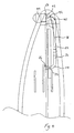
- the light guide 29 has a portion 32 which extends in a rearward direction away from the light emitting diode 26. It then progresses through a curve 34 where it turns through an angle of substantially 90° to a portion 36 which extends upwardly on a slant until it reaches a further portion 38 of the light guide 29 which extends in a substantially vertical direction to a second curved part 40 where the light guide curves through a second angle of substantially 90° to a portion 42 of the light guide which extends in a forward direction and which terminates at a position at its end 43 at which light from the photo-emitting diode 26 can be transmitted outwardly from the fish-bite detector, in a forward direction.
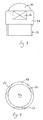
- the light guide 29 at this end is covered by a colour filter lens 44 which is shown in greater detail in Figures 8 and 9.
- a colour filter lens 44 which is shown in greater detail in Figures 8 and 9.
- it has a generally part-spherical light transmitting outer face 46, a generally cylindrical main body portion 48 provided with three equiangularly spaced flats 50 spaced apart on its outside, and a skirt portion 52 which extends from the main body portion 48 and is received as a screw fit or a tight fit in a corresponding aperture 54 in an external wall of the ear portion 16 of the fish-bite detector.
- a tool (not shown) may be provided for this purpose, the tool having a shaped end corresponding to that of the outer part of the filter lens 44, to enable the tool to obtain a purchase on the filter lens 44 and to facilitate the screw action or other insertion without damage to the lens or the casing.
- the printed circuit board 24 is powered by batteries 53 which are held in respective recesses 55 having appropriate contacts 56 which are in turn connected to the printed circuit board 24.
- a fish rod (not shown) is supported by the rod-support part 12 and a line of the rod engages the wheel 20.
- the sensor 22 causes an electrical signal to be sent to the light emitting diode 26.
- the latter emits light which travels through the light guide 29 to its far end 43 where it passes through the colour filter 44 and thence outwardly from the fish-bite detector to provide a visual bite signal to the user.
- the colour filter 44 can be swapped with a filter of a different colour, there being a plurality of such colour filters available to the user or the stockist, each of which can be selectively inserted in the aperture 54 according to the user's taste or colour code system. This reduces the number of different detectors which a stockist must hold, because the colour of the filter lens does not have to be selected until the time of purchase.
- portions 36 and 38 of the light guide may be replaced by a single straight portion which extends directly between the curved portions 34 and 40.
- An O-ring may be inserted under the body portion 48 where it forms a shoulder with the skirt portion 52, to provide a watertight seal against the casing.
Landscapes
- Life Sciences & Earth Sciences (AREA)
- Environmental Sciences (AREA)
- Engineering & Computer Science (AREA)
- Microelectronics & Electronic Packaging (AREA)
- Animal Husbandry (AREA)
- Biodiversity & Conservation Biology (AREA)
- Measurement Of Velocity Or Position Using Acoustic Or Ultrasonic Waves (AREA)
- Farming Of Fish And Shellfish (AREA)
- Mechanical Means For Catching Fish (AREA)
Claims (4)
- Fischanbeißdetektor, der umfasst: ein Rutenauflageteil (12), an dessen gegenüberliegenden Seiten in einer gewünschten Aufwärtsrichtung von einem Hauptkörper des Fischanbeißdetektors jeweilige Ösenabschnitte (14 und 16) vorstehen, um eine seitliche Bewegung einer Rute zu verhindern, wenn der Detektor in Gebrauch ist, ein bewegliches Leineneingrifforgan (20), das so beschaffen ist, dass es in Gebrauch mit der Leine einer solchen Rute in Eingriff gelangt, Sensormittel (22), die mit dem beweglichen Leineneingrifforgan (20) gekoppelt sind, und Signalerzeugungsmittel (24, 26), die mit den Sensormitteln (22) verbunden sind, um bei einer Bewegung des beweglichen Leineneingrifforgans (20) ein Anbeißerfassungssignal auszugeben, wobei die Signalerzeugungsmittel (24, 26) eine lichtemittierende Vorrichtung (26) umfassen, die an einer gedruckten Leiterplatte (24) im Hauptkörper des Detektors angebracht ist und von der sich ein Lichtleiter (29) an eine Stelle erstreckt, an der er Licht von dem Fischanbeißdetektor nach außen senden kann, dadurch gekennzeichnet, dass die lichtemittierende Vorrichtung (26) an einer Rückseite der gedruckten Leiterplatte (24) angebracht ist und der Lichtleiter (29) sich von jener lichtemittierenden Vorrichtung (26) in einer gewünschten Rückwärtsrichtung erstreckt, um einen Winkel (34) in eine Aufwärtsrichtung zu einem der Ösenabschnitte (14 oder 16) gekrümmt ist, wo er um einen zweiten Winkel (40) zu einer Stelle in jenem Ösenabschnitt (14 oder 16) gekrümmt ist, an der er Licht von dem Fischanbeißdetektor in einer Vorwärtsrichtung nach außen senden kann.
- Fischanbeißdetektor nach Anspruch 1, dadurch gekennzeichnet, dass jeder der Winkel (34, 40) im Wesentlichen ein rechter Winkel ist.
- Fischanbeißdetektor nach Anspruch 1 oder Anspruch 2, dadurch gekennzeichnet, dass an jener Stelle eine Befestigung (54) vorgesehen ist, um einen Farbfilter (44) daran anzubringen.
- Fischanbeißdetektor nach Anspruch 3, dadurch gekennzeichnet, dass mehrere Filter mit unterschiedlichen Farben vorgesehen sind, wobei irgendeiner von ihnen ausgewählt und an der Befestigung (54) angebracht werden kann.
Applications Claiming Priority (2)
| Application Number | Priority Date | Filing Date | Title |
|---|---|---|---|
| GB0327393 | 2003-11-25 | ||
| GB0327393A GB0327393D0 (en) | 2003-11-25 | 2003-11-25 | A fish-bite detector |
Publications (2)
| Publication Number | Publication Date |
|---|---|
| EP1535513A1 EP1535513A1 (de) | 2005-06-01 |
| EP1535513B1 true EP1535513B1 (de) | 2007-05-23 |
Family
ID=29797778
Family Applications (1)
| Application Number | Title | Priority Date | Filing Date |
|---|---|---|---|
| EP04256056A Expired - Lifetime EP1535513B1 (de) | 2003-11-25 | 2004-09-30 | Bissanzeiger zum Angeln |
Country Status (4)
| Country | Link |
|---|---|
| EP (1) | EP1535513B1 (de) |
| CN (1) | CN100446667C (de) |
| DE (1) | DE602004006586T2 (de) |
| GB (1) | GB0327393D0 (de) |
Family Cites Families (4)
| Publication number | Priority date | Publication date | Assignee | Title |
|---|---|---|---|---|
| GB2214045B (en) * | 1988-01-22 | 1992-01-08 | Jeffrey Alan Peck | Bite indicators |
| US5276990A (en) * | 1993-02-22 | 1994-01-11 | Ramirez John E | Illuminated fishing pole |
| GB9913345D0 (en) * | 1999-06-08 | 1999-08-11 | Fox Design Int | Light indicator assembly |
| GB0103760D0 (en) * | 2001-02-15 | 2001-04-04 | Fox Design Int | A device for outdoor use |
-
2003
- 2003-11-25 GB GB0327393A patent/GB0327393D0/en not_active Ceased
-
2004
- 2004-09-30 EP EP04256056A patent/EP1535513B1/de not_active Expired - Lifetime
- 2004-09-30 DE DE200460006586 patent/DE602004006586T2/de not_active Expired - Lifetime
- 2004-11-23 CN CNB2004100950655A patent/CN100446667C/zh not_active Expired - Fee Related
Non-Patent Citations (1)
| Title |
|---|
| None * |
Also Published As
| Publication number | Publication date |
|---|---|
| CN100446667C (zh) | 2008-12-31 |
| GB0327393D0 (en) | 2003-12-31 |
| CN1623384A (zh) | 2005-06-08 |
| DE602004006586T2 (de) | 2008-01-24 |
| EP1535513A1 (de) | 2005-06-01 |
| DE602004006586D1 (de) | 2007-07-05 |
Similar Documents
| Publication | Publication Date | Title |
|---|---|---|
| US5229590A (en) | Dome-shaped handheld laser scanner | |
| EP0165523B1 (de) | Vorrichtung zum Messen der Hirnaktivität | |
| US5325143A (en) | Adaptor of camera | |
| EP1099405A4 (de) | Endoskop | |
| US6603402B2 (en) | Water skier alert system and tow bar handle assembly | |
| FI960485A0 (fi) | Autonominen järjestelmä fysiologisten parametrien mittaamiseksi, käsittelemiseksi ja välittämiseksi | |
| EP1617349A3 (de) | Gerät zur Personenerkennung | |
| KR101571262B1 (ko) | 카메라가 구비된 헬멧 | |
| TW200629887A (en) | Imaging device | |
| WO1991010158A3 (en) | Flash illumination system and method incorporating indirect reflecting surface detection | |
| CN105191891B (zh) | 一种防盗竿的钓鱼报警组件 | |
| AU2001261073A1 (en) | Dual mode data imaging product | |
| TW200500256A (en) | Handle stem and speed indicator | |
| US20170363258A1 (en) | Hand mounted mirror and indicator device | |
| EP2147596A1 (de) | Fischbissanzeigevorrichtung | |
| EP1535513A1 (de) | Bissanzeiger zum Angeln | |
| US7109871B2 (en) | Skier alert system with fallen skier alarm | |
| CA2293858A1 (en) | Day light harness adaptor | |
| EP1024078A3 (de) | Fahrradgeschwindigkeitssteuergerät mit einem Geschwindigkeitsanzeiger | |
| EP1207096A3 (de) | Struktur zum Befestigen eines Lenkwinkelsensors für ein Lenkrad | |
| EP0990877A3 (de) | Anordnung zur Wasserverbrauchsbestimmung entlang des Eingangs des Wasserleitungsrohres | |
| EP0390388A3 (de) | Infusionspumpe | |
| US5274219A (en) | Handheld laser scanner with built-in stand | |
| EP0767269A3 (de) | Kombination von Schalter und Signallichtsender für Bügeleisen | |
| WO2004021777A1 (en) | Improved bite alarm for fishing |
Legal Events
| Date | Code | Title | Description |
|---|---|---|---|
| PUAI | Public reference made under article 153(3) epc to a published international application that has entered the european phase |
Free format text: ORIGINAL CODE: 0009012 |
|
| AK | Designated contracting states |
Kind code of ref document: A1 Designated state(s): AT BE BG CH CY CZ DE DK EE ES FI FR GB GR HU IE IT LI LU MC NL PL PT RO SE SI SK TR |
|
| AX | Request for extension of the european patent |
Extension state: AL HR LT LV MK |
|
| 17P | Request for examination filed |
Effective date: 20050826 |
|
| AKX | Designation fees paid |
Designated state(s): BE DE FR GB IT NL |
|
| GRAP | Despatch of communication of intention to grant a patent |
Free format text: ORIGINAL CODE: EPIDOSNIGR1 |
|
| GRAS | Grant fee paid |
Free format text: ORIGINAL CODE: EPIDOSNIGR3 |
|
| GRAA | (expected) grant |
Free format text: ORIGINAL CODE: 0009210 |
|
| AK | Designated contracting states |
Kind code of ref document: B1 Designated state(s): BE DE FR GB IT NL |
|
| REG | Reference to a national code |
Ref country code: GB Ref legal event code: FG4D |
|
| REF | Corresponds to: |
Ref document number: 602004006586 Country of ref document: DE Date of ref document: 20070705 Kind code of ref document: P |
|
| PLBE | No opposition filed within time limit |
Free format text: ORIGINAL CODE: 0009261 |
|
| STAA | Information on the status of an ep patent application or granted ep patent |
Free format text: STATUS: NO OPPOSITION FILED WITHIN TIME LIMIT |
|
| 26N | No opposition filed |
Effective date: 20080226 |
|
| PG25 | Lapsed in a contracting state [announced via postgrant information from national office to epo] |
Ref country code: IT Free format text: LAPSE BECAUSE OF NON-PAYMENT OF DUE FEES Effective date: 20090930 |
|
| PGRI | Patent reinstated in contracting state [announced from national office to epo] |
Ref country code: IT Effective date: 20110616 |
|
| REG | Reference to a national code |
Ref country code: DE Ref legal event code: R082 Ref document number: 602004006586 Country of ref document: DE Representative=s name: LS-MP VON PUTTKAMER BERNGRUBER LOTH SPUHLER PA, DE Ref country code: DE Ref legal event code: R082 Ref document number: 602004006586 Country of ref document: DE Representative=s name: LS-MP VON PUTTKAMER BERNGRUBER LOTH SPUHLER MU, DE Ref country code: DE Ref legal event code: R082 Ref document number: 602004006586 Country of ref document: DE Representative=s name: VP-IP VON PUTTKAMER BERNGRUBER LOTH SPUHLER PA, DE |
|
| REG | Reference to a national code |
Ref country code: DE Ref legal event code: R082 Ref document number: 602004006586 Country of ref document: DE Representative=s name: LS-MP VON PUTTKAMER BERNGRUBER LOTH SPUHLER PA, DE Ref country code: DE Ref legal event code: R082 Ref document number: 602004006586 Country of ref document: DE Representative=s name: LS-MP VON PUTTKAMER BERNGRUBER LOTH SPUHLER MU, DE Ref country code: DE Ref legal event code: R082 Ref document number: 602004006586 Country of ref document: DE Representative=s name: VP-IP VON PUTTKAMER BERNGRUBER LOTH SPUHLER PA, DE |
|
| REG | Reference to a national code |
Ref country code: FR Ref legal event code: PLFP Year of fee payment: 12 |
|
| REG | Reference to a national code |
Ref country code: FR Ref legal event code: PLFP Year of fee payment: 13 |
|
| PGFP | Annual fee paid to national office [announced via postgrant information from national office to epo] |
Ref country code: NL Payment date: 20160926 Year of fee payment: 13 |
|
| PGFP | Annual fee paid to national office [announced via postgrant information from national office to epo] |
Ref country code: FR Payment date: 20160930 Year of fee payment: 13 |
|
| PGFP | Annual fee paid to national office [announced via postgrant information from national office to epo] |
Ref country code: BE Payment date: 20160926 Year of fee payment: 13 |
|
| PGFP | Annual fee paid to national office [announced via postgrant information from national office to epo] |
Ref country code: DE Payment date: 20161130 Year of fee payment: 13 |
|
| PGFP | Annual fee paid to national office [announced via postgrant information from national office to epo] |
Ref country code: IT Payment date: 20160923 Year of fee payment: 13 |
|
| REG | Reference to a national code |
Ref country code: DE Ref legal event code: R119 Ref document number: 602004006586 Country of ref document: DE |
|
| REG | Reference to a national code |
Ref country code: NL Ref legal event code: MM Effective date: 20171001 |
|
| REG | Reference to a national code |
Ref country code: BE Ref legal event code: MM Effective date: 20170930 |
|
| PG25 | Lapsed in a contracting state [announced via postgrant information from national office to epo] |
Ref country code: NL Free format text: LAPSE BECAUSE OF NON-PAYMENT OF DUE FEES Effective date: 20171001 |
|
| REG | Reference to a national code |
Ref country code: FR Ref legal event code: ST Effective date: 20180531 |
|
| PG25 | Lapsed in a contracting state [announced via postgrant information from national office to epo] |
Ref country code: DE Free format text: LAPSE BECAUSE OF NON-PAYMENT OF DUE FEES Effective date: 20180404 |
|
| PG25 | Lapsed in a contracting state [announced via postgrant information from national office to epo] |
Ref country code: IT Free format text: LAPSE BECAUSE OF NON-PAYMENT OF DUE FEES Effective date: 20170930 Ref country code: FR Free format text: LAPSE BECAUSE OF NON-PAYMENT OF DUE FEES Effective date: 20171002 Ref country code: BE Free format text: LAPSE BECAUSE OF NON-PAYMENT OF DUE FEES Effective date: 20170930 |
|
| PGFP | Annual fee paid to national office [announced via postgrant information from national office to epo] |
Ref country code: GB Payment date: 20220929 Year of fee payment: 19 |
|
| GBPC | Gb: european patent ceased through non-payment of renewal fee |
Effective date: 20230930 |
|
| PG25 | Lapsed in a contracting state [announced via postgrant information from national office to epo] |
Ref country code: GB Free format text: LAPSE BECAUSE OF NON-PAYMENT OF DUE FEES Effective date: 20230930 |
|
| PG25 | Lapsed in a contracting state [announced via postgrant information from national office to epo] |
Ref country code: GB Free format text: LAPSE BECAUSE OF NON-PAYMENT OF DUE FEES Effective date: 20230930 |