EP1535083B1 - Microvascular blood volume magnetic resonance imaging - Google Patents
Microvascular blood volume magnetic resonance imaging Download PDFInfo
- Publication number
- EP1535083B1 EP1535083B1 EP03755747A EP03755747A EP1535083B1 EP 1535083 B1 EP1535083 B1 EP 1535083B1 EP 03755747 A EP03755747 A EP 03755747A EP 03755747 A EP03755747 A EP 03755747A EP 1535083 B1 EP1535083 B1 EP 1535083B1
- Authority
- EP
- European Patent Office
- Prior art keywords
- magnetic resonance
- blood
- sequence
- set forth
- inversion
- Prior art date
- Legal status (The legal status is an assumption and is not a legal conclusion. Google has not performed a legal analysis and makes no representation as to the accuracy of the status listed.)
- Expired - Lifetime
Links
- 239000008280 blood Substances 0.000 title claims abstract description 215
- 210000004369 blood Anatomy 0.000 title claims abstract description 206
- 238000002595 magnetic resonance imaging Methods 0.000 title abstract description 22
- 230000005291 magnetic effect Effects 0.000 claims abstract description 119
- 230000005284 excitation Effects 0.000 claims abstract description 42
- 238000002075 inversion recovery Methods 0.000 claims abstract description 27
- 238000004611 spectroscopical analysis Methods 0.000 claims abstract description 7
- 238000005534 hematocrit Methods 0.000 claims abstract description 6
- 230000000694 effects Effects 0.000 claims abstract description 5
- 210000004556 brain Anatomy 0.000 claims description 32
- 238000003384 imaging method Methods 0.000 claims description 27
- 230000002792 vascular Effects 0.000 claims description 27
- 230000008859 change Effects 0.000 claims description 18
- 238000000034 method Methods 0.000 claims description 15
- 210000004204 blood vessel Anatomy 0.000 claims description 8
- 230000005415 magnetization Effects 0.000 claims description 8
- 230000005856 abnormality Effects 0.000 claims description 7
- 238000001646 magnetic resonance method Methods 0.000 claims 22
- 230000001939 inductive effect Effects 0.000 claims 4
- 230000002123 temporal effect Effects 0.000 claims 2
- 238000013178 mathematical model Methods 0.000 claims 1
- 230000006461 physiological response Effects 0.000 claims 1
- 210000001519 tissue Anatomy 0.000 description 62
- 238000013459 approach Methods 0.000 description 11
- 238000005259 measurement Methods 0.000 description 11
- 230000002490 cerebral effect Effects 0.000 description 7
- 210000004088 microvessel Anatomy 0.000 description 7
- 230000008901 benefit Effects 0.000 description 6
- 238000001208 nuclear magnetic resonance pulse sequence Methods 0.000 description 6
- 238000006213 oxygenation reaction Methods 0.000 description 6
- 238000010586 diagram Methods 0.000 description 5
- 208000037265 diseases, disorders, signs and symptoms Diseases 0.000 description 5
- 210000001175 cerebrospinal fluid Anatomy 0.000 description 4
- 201000010099 disease Diseases 0.000 description 4
- 238000002592 echocardiography Methods 0.000 description 4
- XLYOFNOQVPJJNP-UHFFFAOYSA-N water Substances O XLYOFNOQVPJJNP-UHFFFAOYSA-N 0.000 description 4
- 206010028980 Neoplasm Diseases 0.000 description 3
- 210000005013 brain tissue Anatomy 0.000 description 3
- 201000011510 cancer Diseases 0.000 description 3
- 239000002872 contrast media Substances 0.000 description 3
- 210000000056 organ Anatomy 0.000 description 3
- 230000000638 stimulation Effects 0.000 description 3
- 238000012360 testing method Methods 0.000 description 3
- 230000025033 vasoconstriction Effects 0.000 description 3
- 230000024883 vasodilation Effects 0.000 description 3
- 208000006011 Stroke Diseases 0.000 description 2
- 206010047139 Vasoconstriction Diseases 0.000 description 2
- 230000002159 abnormal effect Effects 0.000 description 2
- 230000004075 alteration Effects 0.000 description 2
- 210000003484 anatomy Anatomy 0.000 description 2
- 230000017531 blood circulation Effects 0.000 description 2
- 230000001419 dependent effect Effects 0.000 description 2
- 210000004884 grey matter Anatomy 0.000 description 2
- 238000012417 linear regression Methods 0.000 description 2
- 238000012986 modification Methods 0.000 description 2
- 230000004048 modification Effects 0.000 description 2
- 208000031225 myocardial ischemia Diseases 0.000 description 2
- 230000001537 neural effect Effects 0.000 description 2
- 101150093826 par1 gene Proteins 0.000 description 2
- 238000011112 process operation Methods 0.000 description 2
- 230000009467 reduction Effects 0.000 description 2
- 230000004044 response Effects 0.000 description 2
- 238000005070 sampling Methods 0.000 description 2
- 230000001052 transient effect Effects 0.000 description 2
- 210000004885 white matter Anatomy 0.000 description 2
- 208000022211 Arteriovenous Malformations Diseases 0.000 description 1
- 102000001554 Hemoglobins Human genes 0.000 description 1
- 108010054147 Hemoglobins Proteins 0.000 description 1
- 241001465754 Metazoa Species 0.000 description 1
- 238000003491 array Methods 0.000 description 1
- 230000005744 arteriovenous malformation Effects 0.000 description 1
- 230000033228 biological regulation Effects 0.000 description 1
- 230000008081 blood perfusion Effects 0.000 description 1
- 230000007177 brain activity Effects 0.000 description 1
- 230000001684 chronic effect Effects 0.000 description 1
- 239000002131 composite material Substances 0.000 description 1
- 150000001875 compounds Chemical class 0.000 description 1
- 238000001514 detection method Methods 0.000 description 1
- 238000002059 diagnostic imaging Methods 0.000 description 1
- 208000035475 disorder Diseases 0.000 description 1
- 229940079593 drug Drugs 0.000 description 1
- 239000003814 drug Substances 0.000 description 1
- 238000002474 experimental method Methods 0.000 description 1
- 230000006870 function Effects 0.000 description 1
- 238000002599 functional magnetic resonance imaging Methods 0.000 description 1
- 230000013632 homeostatic process Effects 0.000 description 1
- 208000000122 hyperventilation Diseases 0.000 description 1
- 230000000870 hyperventilation Effects 0.000 description 1
- 230000001771 impaired effect Effects 0.000 description 1
- 238000012625 in-situ measurement Methods 0.000 description 1
- 230000002452 interceptive effect Effects 0.000 description 1
- 230000003902 lesion Effects 0.000 description 1
- 238000002610 neuroimaging Methods 0.000 description 1
- 238000010606 normalization Methods 0.000 description 1
- 229910052760 oxygen Inorganic materials 0.000 description 1
- 239000001301 oxygen Substances 0.000 description 1
- 230000005298 paramagnetic effect Effects 0.000 description 1
- 230000007170 pathology Effects 0.000 description 1
- 230000037361 pathway Effects 0.000 description 1
- 230000004962 physiological condition Effects 0.000 description 1
- 238000002600 positron emission tomography Methods 0.000 description 1
- 238000002360 preparation method Methods 0.000 description 1
- 230000008569 process Effects 0.000 description 1
- 238000012545 processing Methods 0.000 description 1
- 238000011084 recovery Methods 0.000 description 1
- 238000011160 research Methods 0.000 description 1
- 230000035945 sensitivity Effects 0.000 description 1
- 238000002603 single-photon emission computed tomography Methods 0.000 description 1
- 238000009662 stress testing Methods 0.000 description 1
- 239000000126 substance Substances 0.000 description 1
- 230000002889 sympathetic effect Effects 0.000 description 1
- 230000017105 transposition Effects 0.000 description 1
- 208000019553 vascular disease Diseases 0.000 description 1
- 229940124549 vasodilator Drugs 0.000 description 1
- 239000003071 vasodilator agent Substances 0.000 description 1
- 230000000007 visual effect Effects 0.000 description 1
Images


Classifications
-
- G—PHYSICS
- G01—MEASURING; TESTING
- G01R—MEASURING ELECTRIC VARIABLES; MEASURING MAGNETIC VARIABLES
- G01R33/00—Arrangements or instruments for measuring magnetic variables
- G01R33/20—Arrangements or instruments for measuring magnetic variables involving magnetic resonance
- G01R33/44—Arrangements or instruments for measuring magnetic variables involving magnetic resonance using nuclear magnetic resonance [NMR]
- G01R33/48—NMR imaging systems
- G01R33/50—NMR imaging systems based on the determination of relaxation times, e.g. T1 measurement by IR sequences; T2 measurement by multiple-echo sequences
-
- A—HUMAN NECESSITIES
- A61—MEDICAL OR VETERINARY SCIENCE; HYGIENE
- A61B—DIAGNOSIS; SURGERY; IDENTIFICATION
- A61B5/00—Measuring for diagnostic purposes; Identification of persons
- A61B5/05—Detecting, measuring or recording for diagnosis by means of electric currents or magnetic fields; Measuring using microwaves or radio waves
- A61B5/055—Detecting, measuring or recording for diagnosis by means of electric currents or magnetic fields; Measuring using microwaves or radio waves involving electronic [EMR] or nuclear [NMR] magnetic resonance, e.g. magnetic resonance imaging
-
- G—PHYSICS
- G01—MEASURING; TESTING
- G01R—MEASURING ELECTRIC VARIABLES; MEASURING MAGNETIC VARIABLES
- G01R33/00—Arrangements or instruments for measuring magnetic variables
- G01R33/20—Arrangements or instruments for measuring magnetic variables involving magnetic resonance
- G01R33/44—Arrangements or instruments for measuring magnetic variables involving magnetic resonance using nuclear magnetic resonance [NMR]
- G01R33/48—NMR imaging systems
- G01R33/483—NMR imaging systems with selection of signals or spectra from particular regions of the volume, e.g. in vivo spectroscopy
-
- G—PHYSICS
- G01—MEASURING; TESTING
- G01R—MEASURING ELECTRIC VARIABLES; MEASURING MAGNETIC VARIABLES
- G01R33/00—Arrangements or instruments for measuring magnetic variables
- G01R33/20—Arrangements or instruments for measuring magnetic variables involving magnetic resonance
- G01R33/44—Arrangements or instruments for measuring magnetic variables involving magnetic resonance using nuclear magnetic resonance [NMR]
- G01R33/48—NMR imaging systems
- G01R33/54—Signal processing systems, e.g. using pulse sequences ; Generation or control of pulse sequences; Operator console
- G01R33/56—Image enhancement or correction, e.g. subtraction or averaging techniques, e.g. improvement of signal-to-noise ratio and resolution
- G01R33/563—Image enhancement or correction, e.g. subtraction or averaging techniques, e.g. improvement of signal-to-noise ratio and resolution of moving material, e.g. flow contrast angiography
Definitions
- the following relates to the diagnostic imaging arts. It finds particular application in non-invasive measurement by magnetic resonance imaging of cerebral blood volumes, and will be described with particular reference thereto. However, it also finds application in measurement by magnetic resonance imaging of blood volumes in other tissues.
- In-situ measurement of blood volume is useful in various clinical, diagnostic, and research applications.
- Local cerebral blood volume changes for example, correlate with local neuronal activity in the brain.
- Cerebral blood volume measurements during physiological stimulation thus provides a tool for functional studies of brain activity.
- Cerebral blood volume measurements can also provide information about impaired and/or damaged tissue in stroke victims, as well as about lesions in many disorders, including, but not limited to cancer, vascular disorders, and the like.
- Blood volume imaging of other organs besides the brain can similarly provide functional and diagnostic data that is useful in clinical studies, diagnoses, and tests (e.g. stress tests or tests of vascular compliance).
- positron emission tomography single photon emission computed tomography
- magnetic resonance imaging various paramagnetic contrast gents are commonly used for this purpose.
- the requirement of an administered contrast agent is a substantial disadvantage of these techniques.
- Magnetic resonance imaging of blood oxygenation level dependence is a non-invasive technique for indirectly measuring blood volume.
- blood hemoglobin is used as an endogenous contrast agent.
- magnetic resonance imaging is performed as a function of physiological stimulation that causes changes in blood oxygenation level.
- Blood volume is estimated from BOLD measurements by making assumptions pertaining to other parameters that affect blood oxygenation level, such as blood flow. Hence, BOLD does not provide a direct measure of the blood volume.
- a disadvantage of both the invasive techniques and the BOLD techniques as applied to blood volume measurement is that these existing techniques generally do not differentiate between blood in large blood vessels, on the one hand, and perfused blood in small capillaries or other microvessels, on the other hand.
- the blood volume in larger blood vessels is principally controlled by sympathetic regulation.
- blood volume in microvessels having typical diameters of less than about 200 microns tends to vary to maintain local homeostasis or in response to chemicals such as vasodilators or vasorestrictive compounds. Consequently, the blood volume of microvessels responds to physiological perturbations such as local neuronal activity.
- the volume of blood in the microvessels is typically of principle interest, while the blood signal from larger blood vessels is interfering and thus undesirable.
- total microvascular plus macrovascular blood volume may change in some diseases, including but not limited to for instance arteriovenous malformations.
- the present invention contemplates an improved apparatus and method that overcomes the aforementioned limitations and others.
- a magnetic resonance imaging method is provided.
- a blood-nulling magnetic resonance excitation sequence is performed that substantially nulls a magnetic resonance signal from blood.
- a readout magnetic resonance sequence is performed to acquire a magnetic resonance signal from tissue other than the nulled blood.
- a magnetic resonance system is disclosed.
- a blood nulling means is provided for performing a blood nulling magnetic resonance excitation sequence that substantially nulls a magnetic resonance signal from blood.
- a readout means is provided for performing a readout magnetic resonance sequence to acquire a magnetic resonance signal from tissue other than the nulled blood, the readout means operating subsequent to operation of the blood nulling means.
- One advantage resides in measuring the parenchymal vascular space occupancy, which is more sensitive to physiological perturbations than is the total vascular volume which includes the large blood vessels.
- Another advantage resides in providing measurements of the absolute blood volume.
- Yet another advantage resides in providing images with substantially nulled blood magnetic resonance signal, i.e. a blood signal reduction sufficient to have MRI signal remaining that is predominantly from other tissues.
- the invention may take form in various components and arrangements of components, and in various process operations and arrangements of process operations.
- the drawings are only for the purpose of illustrating preferred embodiments and are not to be construed as limiting the invention.
- a magnetic resonance imaging scanner 10 includes main magnet coils 12, which are preferably superconducting coils, although resistive main magnet coils or a permanent magnet can also be employed.
- the main magnet coils 12 are energized to generate a substantially uniform main magnetic field in an examination region 14.
- Magnetic field gradient coils 16 produce gradients in selected spatial directions to spatially encode magnetic resonances that are generated by energizing a radio frequency coil 18.
- a whole-body radio frequency coil 18 is shown; however, local coils such as head coils, phased radio frequency coil arrays, SENSE coils, and the like can be used instead of or in conjunction with the whole-body radio frequency coil 18 to excite magnetic resonances and/or to detect magnetic resonance echoes.
- a magnetic resonance sequence controller 30 coordinates and controls a radio frequency transmitter 34 that is coupled to the whole-body radio frequency coil 18 or another radio frequency coil to excite magnetic resonance echoes, and controls magnetic field gradient controllers 32 coupled to the gradient coils 16 to spatially encode the excited magnetic resonance echoes.
- One or more radio frequency receivers 36 coupled to the whole-body radio frequency coil 18 or another radio frequency coil detects, demodulates, and digitizes the magnetic resonance echoes and stores digital magnetic resonance samples in a k-space memory 40.
- a reconstruction processor 44 performs a Fourier transform-based image reconstruction or other type of image reconstruction to generate one or more reconstructed images from the stored k-space magnetic resonance samples.
- the reconstructed images are stored in an image memory 46, processed by a video processor 50 and displayed on a user interface 52, transmitted over a local computer network or the Internet, or otherwise processed.
- the user interface 52 includes a display, printer, or other output device that allows a radiologist or other operator to view, render, or otherwise manipulate the reconstructed images.
- the user interface 52 preferably enables the radiologist or other operator to communicate with the magnetic resonance sequence controller 30 to create magnetic resonance imaging sequences, modify imaging sequences, execute imaging sequences, or otherwise control the magnetic resonance imaging scanner 10.
- VASO vascular space occupancy
- a suitable value for the inversion time (TI) 60 for nulling blood can be obtained in a number of ways.
- a blood T1 measuring sequence 62 is applied by the sequence controller 30 to measure a T1 value of a representative blood sample using a blood perfusion apparatus, and the inversion time (TI) 60 is computed therefrom.
- a major blood vessel can be identified in a reconstructed image, and a direct measurement of the T1 value of blood inside the identified blood vessel is obtained using conventional magnetic resonance imaging sequences.
- suitable inversion times can be computed from measurements of a representative blood sample of substantially normal human blood or of animal blood of suitable mammalian origin and collected in a table 64, such as Table I and Table II contained herein. These values are generally suitable for substantially normal human blood, and include inversion time dependence upon the main magnetic field strength (Table I providing values for a 1.5T field, and Table II providing values for a 3.0T field) and on the sequence repeat time (TR). Rather than employing tabulated data, the inversion time 60 can be related to magnetic field strength, repeat time TR, and optionally other parameters by an empirical functional relationship or other suitable relationship.
- the tabulated TI values are preferably used as a guideline for determining an inversion time TI that substantially nulls blood so that signals are predominantly from tissue.
- the tabulated values do not exclude other TI values that can also accomplish blood nulling.
- An inversion time adjustment is optionally performed to compensate for deviations in blood T1 value resulting from abnormal hematocrit values, sickle-cell pathologies, or another blood abnormality of a specific imaging subject.
- the blood-nulling inversion recovery imaging sequence is performed for several inversion times around the blood nulling inversion time selected from Tables I and II, and the blood nulling inversion time 60 is selected as the inversion time providing substantially negligible image signal from a large blood vessel.
- a data flow line 66 in FIGURE 1 corresponds to selecting the blood nulling inversion time 60 based on magnetic resonance measurements performed using the scanner 10.
- FIGURE 2 diagrammatically shows a suitable magnetic resonance imaging pulse sequence employing a blood-nulling inversion recovery magnetic resonance excitation sequence 70 to null the blood signal, and an exemplary single shot echo planar imaging readout 72.
- the echo planar imaging readout is exemplary only, and does not exclude employing additional or other magnetic resonance imaging, magnetic resonance spectroscopy or localized spectroscopy detection schemes.
- the readout sequence 72 can be a single-shot imaging sequence, a single-shot echo planar sequence, a multi-shot imaging sequence, a spectroscopy sequence, a multiple slice image, a one-dimensional, two-dimensional, or three dimensional spatial encoding sequence, a fractional k-space acquisition sequence, a spin echo readout sequence, a gradient echo readout sequence, or the like.
- an inversion pulse 74 is applied to invert the spins.
- the inversion pulse 74 is a 180° pulse implementing a 180° flip angle for the spins.
- the inversion time TI 60 is substantially representative to induce proper blood signal reduction based on the T1 value of blood for the particular experimental conditions (field, hematocrit, oxygenation, etc). It is also contemplated, however, to use an inversion pulse having a flip angle greater than 90° but other than 180°, in which case the appropriate inversion time TI 60 is readily computed from the proper T1 and acquisition parameters such as the repetition time TR.
- the inversion time TI 60 is selected as a time during which the longitudinal component of the flipped spins of blood decay from the flip angle to the crossover or null position.
- the null condition corresponds to a zero-crossing point of the longitudinal spin component; as the longitudinal spin component decays from the flipped or inverted alignment back toward the normal, non-inverted alignment it passes through a point where the longitudinal component passes substantially through zero, that is, the longitudinal spin component through a substantially zero crossing point.
- Substantially zero is understood to correspond to a substantially negligible blood signal such that the acquired magnetic resonance signal predominantly contains signals from tissues other than blood.
- the inversion pulse 74 is not accompanied by a spatial encoding magnetic field gradient pulse or is accompanied by a relatively small spatial encoding magnetic field gradient pulse. This ensures that the spins of blood throughout the subject region of interest reach the null condition after the inversion time delay TI 60.
- the blood nulling is independent of blood flow since the blood-nulling inversion pulse 74 is spatially non-selective or selects a relatively large region. Thus, flowing blood that flows into the slice of interest at the time of excitation or at the time of readout is nulled appropriately.
- an excitation pulse 80 is applied in conjunction with a slice-selective magnetic field gradient pulse 82 to excite spins in a selected slice of the subject region of interest.
- the excitation pulse 80 is preferably a 90° excitation pulse having a flip angle of 90°; however, an excitation pulse with other than a 90° flip angle is also contemplated. Because the blood is in a null condition at the time the excitation pulse 80 is applied, negligible magnetic resonance signal is excited in the nulled blood by the excitation pulse 80.
- Tissue such as fat, gray and white brain tissues, and the like generally have a different T1 value from that of blood, and so these tissues are not at a null condition at the time the excitation pulse 80 is applied. Hence, the excitation pulse 80 excites magnetic resonance predominantly in tissue.
- the exemplary single shot echo planar imaging readout 72 samples the magnetic resonance excited in the tissue by the excitation pulse 80.
- the illustrated single shot echo planar imaging readout 72 is a conventional readout including a 180° spin refocusing radio frequency pulse 84 and slice-selective gradient pulse 86 that create a spin echo in a selected slice at a time-to-echo interval TE after the excitation pulse 80.
- a series of phase-encoding magnetic field gradient pulses 88 and a generally sinusoidal read magnetic field gradient waveform 90 step through a grid of k-space values in the selected slice while the radio frequency receiver 36 of FIGURE 1 performs sampling 92 of the spin echo.
- the magnetic resonance signal k-space samples are stored in the k-space memory 40 of FIGURE 1 and are processed to produce a reconstructed image representation as described previously.
- the single shot echo planar imaging readout 72 shown in FIGURE 2 is exemplary only. Substantially any type of magnetic resonance imaging or magnetic resonance spectroscopy readout or acquisition sequence can be employed.
- the readout sequence may be a fast, single-shot sequence that acquires at least one slice per excitation.
- the exemplary single shot echo planar imaging readout 72 can be replaced by a short gradient echo readout sequence.
- An echo time (TE) of the readout shown in FIGURE 2 is preferably kept short so that the readout is performed while the blood remains substantially in the nulled condition and to minimize contributions such as those from the blood-oxygen-level-dependent (BOLD) effect.
- one or more additional inversion pulses are applied to keep the blood close to the null condition during longer readout sequences.
- the inversion recovery blood-nulling sequence 70 is preferred, other pulse sequences can be employed to substantially null the blood signal so that the magnetic resonance is predominantly due to tissues other than blood.
- TE long echo time
- BOLD extravascular blood oxygenation level dependence
- CBV cerebral blood volumes
- the CBV contribution is quantified from interpolation of the TE dependence from a series of TE values at sufficiently long TE to avoid intravascular contributions that would occur at shorter TE and/or from differences between such interpolations under different physiological conditions or between normal and diseased tissue.
- the blood-nulling magnetic resonance sequence of FIGURE 2 is optionally repeated with a repetition time (TR) to acquire reconstructed images for multiple slices or for multiple three-dimensional (3D), two-dimensional (2D), or one-dimensional (1D) spatial encodings, for example to obtain a three-dimensional reconstructed image volume.
- TR repetition time
- an exemplary succeeding spatially non-selective inversion recovery pulse 74' corresponds to the beginning of the next repetition of the blood-nulling imaging sequence.
- the blood nulling establishes a substantially negligible blood signal, it is possible to acquire multiple slices or multiple 1D, 2D, or 3D spatial encodings per single nulling condition. This applies to both imaging and spectroscopy applications.
- Reconstructed images acquired using inversion-recovery blood-nulling magnetic resonance sequences such as the exemplary sequence of FIGURE 2 can be used in various ways.
- the determined weighting values are typically composite values having contributions from both blood and tissue.
- ⁇ , T1, and T2 weightings for tissue can be obtained without interference from the blood signal.
- other tissues are nulled in addition to blood, to minimize contributions from those other tissues or components.
- such combined blood and tissue nulling can be used to largely isolate a magnetic resonance signal from cerebral spinal fluid (CSF) in the brain.
- CSF cerebral spinal fluid
- Reconstructed images acquired using inversion-recovery blood-nulling magnetic resonance sequences contain information pertaining to vascular space occupancy insofar as the images includes contributions from tissue but substantially exclude contributions from the blood volume.
- the blood volume can be changed. For example, cerebral blood volume undergoes vasodilation responsive to visual stimulation and breath-hold. Similarly, cerebral blood volume undergoes vasoconstriction responsive to hyperventilation. Blood volume changes can also be induced by administration of a selected drug, for example, but not limited to, for stress testing or the assessment of vascular compliance.
- certain diseases such as cardiac ischemia, stroke, cancer, vascular deformations, and the like, represent a chronic or transient physiological perturbation that can case a change in blood volume detectable with the methodology described herein.
- the change in blood volume occurs principally in the microvessels rather than in the large vessels and parenchyma.
- the blood volume changes measured using the blood-nulled reconstructed images reflect the parenchymal blood volume (denoted BV herein) which substantially corresponds to the volume of the microvessels without contributions from the larger vessels.
- vascular volume effects measured by BOLD and many other existing techniques include the large vessels and parenchyma and other tissues close to these vessels (for example, cerebral spinal fluid).
- the measured parenchymal vascular space occupancy ⁇ advantageously is more sensitive to physiological perturbation, including permanent disease-induced perturbation, than is the total vascular volume. Changes in large-vessel volume (that is, outside parenchymal regions) are also accessible by the blood nulling approach. At appropriate resolution, changes in large-vessel volume do not interfere with the indicated parenchymal blood volume changes due to the applied spatial encoding.
- the magnetic resonance signal (denoted by S herein) is proportional to a sum of the magnetization contributions of the microvessels and of the pure tissue.
- Equation (2) Inserting the vascular space occupancy ⁇ and water density factors C par and C blood for parenchymal tissue and blood, respectively, into Equation (2) yields: S par ⁇ C blood ⁇ ⁇ ⁇ M blood ⁇ e - TE / T ⁇ 2 blood + C par - ⁇ ⁇ C blood ⁇ M tissue ⁇ e - TE / T ⁇ 2 tissue
- T2 blood and T2 tissue are suitable time constants for the exemplary spin echo readout 72 of FIGURE 2 due to the spin refocusing produced by the radio frequency pulse 84.
- the T2 values should be replaced by T2* values in Equation (3).
- M blood and M tissue correspond to the initial transverse magnetization of the blood and the tissue, respectively, produced by the excitation radio frequency pulse 80.
- M blood corresponding to the blood is substantially zero, and so Equation (3) reduces to: S par ⁇ C par - ⁇ ⁇ C blood ⁇ M tissue ⁇ e - TE / T ⁇ 2 tissue
- ⁇ S S 1 - ⁇ act ⁇ C blood C par ⁇ e - TE / T ⁇ 2 tissue act - 1 / T ⁇ 2 tissue rest - ( 1 - ⁇ rest ⁇ C blood C par ) 1 - ⁇ rest ⁇ C blood C par
- FIGURE 3 shows a block diagram of an exemplary processor 100 that computes a rest blood volume BV rest and a blood volume change ⁇ BV based on Equation (10).
- the processor 100 receives imaging data input from the image memory 46.
- the imaging data includes images taken at a plurality of echo times TE 102 with the imaging subject at rest, and corresponding images taken at the plurality of (that is, two or more) echo times TE with the imaging subject in a perturbed state.
- a processor 104 computes the fractional signal difference ⁇ S/S between the image of the subject in the rest state and the image of the subject in the perturbed state for each echo time TE to form a table 106 of fractional signal difference ⁇ S/S versus echo time TE.
- Equation (10) is a linear equation in echo time TE
- a linear regression processor 110 computes a slope 112 and an ordinate-intercept 114 of the ⁇ S/S v. TE relationship.
- Equation (11) is the slope component of the linear relationship between AS/S and TE of Equation (10).
- the rightmost side of Equation (11) is written with the rest parenchymal vascular space occupancy ⁇ rest replaced by blood volume BV rest divided by the volume V par of the parenchymal tissue under consideration in accordance with Equation (1).
- the BV rest calculator 116 uses literature values for the water density factors C par and C blood , the known volume V par of the parenchymal tissue under consideration, and a value for ⁇ R2 calculated from T2 tissue,act and T2 tissue,rest values obtained by fitting the signal value S at several echo times TE for each of the perturbed and rest states, respectively. If V par is unknown, the method can be used to determine the absolute blood volume fraction or vascular space occupancy ( ⁇ rest ).
- the ⁇ BV calculator 122 uses literature values for the water density factors C par and C blood , the known volume V par of the parenchymal tissue under consideration, and the rest blood volume BV rest 118 computed by the BV rest calculator 116. Alternatively, the absolute blood volume fraction or vascular space occupancy ( ⁇ rest ) can be used if V par is unknown.
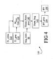
- FIGURE 4 shows a block diagram of another processor 130 that computes an absolute blood volume BV.
- Computation of BV by the processor 130 is not based on a transient response to a physiological perturbation. Rather, data from the image memory 46, which may be a single image, is processed using Equation (4).
- the image is preferably acquired using a short echo time TE, so that the term exp(-TE/T2 tissue ) in Equation (4) is suitably approximated as unity so that the signal S is given by: S par ⁇ C par - BV V par ⁇ C blood ⁇ M tissue where the parenchymal vascular space occupancy ⁇ is replaced by the expression in Equation (1).
- TR is the repetition time of the pulse sequence (indicated, for example, in FIGURE 2 ).
- a suitable value for T1 tissue can be measured using a known magnetic resonance technique such as saturation recovery pulse sequence and inversion recovery pulse sequence or, preferably, by a series of inversion pulses so that blood remains substantially nulled, while tissue signal decays with the representative T1 tissue .
- a known magnetic resonance technique such as saturation recovery pulse sequence and inversion recovery pulse sequence or, preferably, by a series of inversion pulses so that blood remains substantially nulled, while tissue signal decays with the representative T1 tissue .
- brain imaging it is known that the T1 tissue values for white and gray brain matter differ.
- a T1 white value 132 and a T1 gray value 134 are preferably determined.
- S par also contains instrumental factors, for instance related to coil sensitivity and excitation homogeneity, the combined contribution of which we will call IF.
- This constant can also be determined during the T1 measurement from the voxels in ventricles, which only contains CSF and has a proton density very close to pure water.
- a blood volume processor 144 estimates the absolute blood volume BV 146 or the absolute blood volume fraction or vascular space occupancy ( ⁇ rest ) by applying Equation (13) to the normalized image 142.
- FIGURE 5 shows a processor 150 that computes a clinical image from blood-nulled magnetic resonance images.
- the processor 150 is suitable in diagnostic applications for detecting an abnormality such as vasodilation or vasoconstriction caused by certain diseases such as cardiac ischemia, stroke, cancer, and the like.
- the image memory 46 stores an image of the imaging subject to be diagnosed.
- the image is compared with a reference image 152 by a difference processor 154 to generate a clinical image 156.
- the difference processor 154 computes an absolute difference between the images, so that normal areas appear dark in the clinical image 156 whereas abnormal areas appear brighter in the clinical image 156 (or vice versa) due to differences between the subject image and the reference image in the vicinity of the abnormality.
- the difference processor 154 computes a signed difference with a constant intensity level offset.
- regions of vasodilation and regions of vasocontraction have opposite intensity polarities respective to the constant intensity level.
- the reference image 152 can be obtained from various sources.
- an image of a normal subject can be employed for the comparison.
- a contralateral image can be used.
- a suspect right-side of the brain can be compared with a presumed normal left-side of the brain, preferably after a suitable left-right transposition of the contralateral comparison image.
- a suspect portion of the organ can be compared with presumed normal portion of the same organ.
- the normalized image 142 of FIGURE 4 is optionally employed in the processor 150.
- the normalized image 142 advantageously has suppressed contrast between white matter regions and gray matter regions of the brain image, which makes the vascular space occupancy contrast more visible.
- large vessels changes may occur in addition to microvascular changes. These can also be detected, and, at sufficient spatial resolution, can be separated from the microvascular changes.
- TE table 110 Linear regression processor 112 Slope 114 Ordinate-intercept 116 Rest blood volume calculator 118 Rest blood volume 122 Blood volume change rate calculator 124 Blood volume change rate 130 Processor for computing absolute blood volume 132 T1 value for white brain tissue 134 T1 value for gray brain tissue 136 M tissue calculator 140 Tissue normalizing processor 142 Normalized image 144 Blood volume processor 146 Blood volume 150 Processor for generating a clinical image 152 Reference image 154 Difference processor 156 Clinical image
Abstract
Description
- The following relates to the diagnostic imaging arts. It finds particular application in non-invasive measurement by magnetic resonance imaging of cerebral blood volumes, and will be described with particular reference thereto. However, it also finds application in measurement by magnetic resonance imaging of blood volumes in other tissues.
- In-situ measurement of blood volume is useful in various clinical, diagnostic, and research applications. Local cerebral blood volume changes, for example, correlate with local neuronal activity in the brain. Cerebral blood volume measurements during physiological stimulation thus provides a tool for functional studies of brain activity. Cerebral blood volume measurements can also provide information about impaired and/or damaged tissue in stroke victims, as well as about lesions in many disorders, including, but not limited to cancer, vascular disorders, and the like. Blood volume imaging of other organs besides the brain can similarly provide functional and diagnostic data that is useful in clinical studies, diagnoses, and tests (e.g. stress tests or tests of vascular compliance).
- Various imaging modalities have been used to measure blood volume characteristics, including positron emission tomography, single photon emission computed tomography, and magnetic resonance imaging. Most of these are invasive approaches, in which the subject is administered a suitable contrast agent that selectively enhances blood contrast in the selected imaging modality. For magnetic resonance imaging, various paramagnetic contrast gents are commonly used for this purpose. The requirement of an administered contrast agent is a substantial disadvantage of these techniques.
- Magnetic resonance imaging of blood oxygenation level dependence (BOLD) is a non-invasive technique for indirectly measuring blood volume. In this technique, blood hemoglobin is used as an endogenous contrast agent. In one BOLD imaging approach, magnetic resonance imaging is performed as a function of physiological stimulation that causes changes in blood oxygenation level. Blood volume is estimated from BOLD measurements by making assumptions pertaining to other parameters that affect blood oxygenation level, such as blood flow. Hence, BOLD does not provide a direct measure of the blood volume.
- A disadvantage of both the invasive techniques and the BOLD techniques as applied to blood volume measurement is that these existing techniques generally do not differentiate between blood in large blood vessels, on the one hand, and perfused blood in small capillaries or other microvessels, on the other hand. The blood volume in larger blood vessels is principally controlled by sympathetic regulation. In contrast, blood volume in microvessels having typical diameters of less than about 200 microns tends to vary to maintain local homeostasis or in response to chemicals such as vasodilators or vasorestrictive compounds. Consequently, the blood volume of microvessels responds to physiological perturbations such as local neuronal activity. For functional magnetic resonance imaging, the volume of blood in the microvessels is typically of principle interest, while the blood signal from larger blood vessels is interfering and thus undesirable. On the other hand, total microvascular plus macrovascular blood volume may change in some diseases, including but not limited to for instance arteriovenous malformations.
- The present invention contemplates an improved apparatus and method that overcomes the aforementioned limitations and others.
- According to one aspect, a magnetic resonance imaging method is provided. A blood-nulling magnetic resonance excitation sequence is performed that substantially nulls a magnetic resonance signal from blood. Subsequent to the performing of the blood-nulling magnetic resonance excitation sequence, a readout magnetic resonance sequence is performed to acquire a magnetic resonance signal from tissue other than the nulled blood.
- According to another aspect, a magnetic resonance system is disclosed. A blood nulling means is provided for performing a blood nulling magnetic resonance excitation sequence that substantially nulls a magnetic resonance signal from blood. A readout means is provided for performing a readout magnetic resonance sequence to acquire a magnetic resonance signal from tissue other than the nulled blood, the readout means operating subsequent to operation of the blood nulling means.
- One advantage resides in measuring the parenchymal vascular space occupancy, which is more sensitive to physiological perturbations than is the total vascular volume which includes the large blood vessels.
- Another advantage resides in providing measurements of the absolute blood volume.
- Yet another advantage resides in providing images with substantially nulled blood magnetic resonance signal, i.e. a blood signal reduction sufficient to have MRI signal remaining that is predominantly from other tissues.
- Numerous additional advantages and benefits will become apparent to those of ordinary skill in the art upon reading the following detailed description of the preferred embodiments.
- The invention may take form in various components and arrangements of components, and in various process operations and arrangements of process operations. The drawings are only for the purpose of illustrating preferred embodiments and are not to be construed as limiting the invention.
-
FIGURE 1 diagrammatically shows a magnetic resonance imaging system for measuring vascular space occupancy. -
FIGURE 2 diagrammatically shows a magnetic resonance imaging pulse sequence employing inversion recovery to null the blood signal. InFIGURE 2 , the time intervals TI, TE, TR are not drawn to scale. -
FIGURE 3 shows a block diagram of a processor for computing a blood volume at rest and a blood volume change occurring responsive to a physiological perturbation. -
FIGURE 4 shows a block diagram of a processor for computing absolute blood volume using a reconstructed image acquired with the blood signal nulled by an inversion recovery preparation. -
FIGURE 5 shows a block diagram of a processor for computing a difference image having enhanced contrast for vascular space occupancy abnormalities. - With reference to
FIGURE 1 , a magneticresonance imaging scanner 10 includesmain magnet coils 12, which are preferably superconducting coils, although resistive main magnet coils or a permanent magnet can also be employed. Themain magnet coils 12 are energized to generate a substantially uniform main magnetic field in anexamination region 14. Magneticfield gradient coils 16 produce gradients in selected spatial directions to spatially encode magnetic resonances that are generated by energizing aradio frequency coil 18. InFIGURE 1 , a whole-bodyradio frequency coil 18 is shown; however, local coils such as head coils, phased radio frequency coil arrays, SENSE coils, and the like can be used instead of or in conjunction with the whole-bodyradio frequency coil 18 to excite magnetic resonances and/or to detect magnetic resonance echoes. - A magnetic
resonance sequence controller 30 coordinates and controls aradio frequency transmitter 34 that is coupled to the whole-bodyradio frequency coil 18 or another radio frequency coil to excite magnetic resonance echoes, and controls magneticfield gradient controllers 32 coupled to thegradient coils 16 to spatially encode the excited magnetic resonance echoes. One or moreradio frequency receivers 36 coupled to the whole-bodyradio frequency coil 18 or another radio frequency coil detects, demodulates, and digitizes the magnetic resonance echoes and stores digital magnetic resonance samples in a k-space memory 40. Areconstruction processor 44 performs a Fourier transform-based image reconstruction or other type of image reconstruction to generate one or more reconstructed images from the stored k-space magnetic resonance samples. - The reconstructed images are stored in an
image memory 46, processed by avideo processor 50 and displayed on auser interface 52, transmitted over a local computer network or the Internet, or otherwise processed. Preferably, theuser interface 52 includes a display, printer, or other output device that allows a radiologist or other operator to view, render, or otherwise manipulate the reconstructed images. Moreover, theuser interface 52 preferably enables the radiologist or other operator to communicate with the magneticresonance sequence controller 30 to create magnetic resonance imaging sequences, modify imaging sequences, execute imaging sequences, or otherwise control the magneticresonance imaging scanner 10. - With continuing reference to
FIGURE 1 , for clinical or diagnostic applications in which the blood volume is of interest, a measure of the vascular space occupancy (VASO) is performed. The approach uses an inversion recovery magnetic resonance excitation sequence having aninversion time 60 optimized for substantial nulling of the blood signal based on a blood T1 value particular to a certain magnetic field strength and hematocrit range. The inversion recovery magnetic resonance excitation sequence substantially nulls the signal from blood so that the magnetic resonance signal corresponds predominantly to tissue, with substantially negligible contribution of blood. This approach takes advantage of a substantial independence of the T1 value of blood on blood oxygenation, which allows the inversion recovery blood nulling to be operative for different types of vessels (arterial, arteriolar, capillary, venular, and venous) as well as throughout a physiological perturbation cycle. - A suitable value for the inversion time (TI) 60 for nulling blood can be obtained in a number of ways. In one suitable approach, a blood
T1 measuring sequence 62 is applied by thesequence controller 30 to measure a T1 value of a representative blood sample using a blood perfusion apparatus, and the inversion time (TI) 60 is computed therefrom. Alternatively, a major blood vessel can be identified in a reconstructed image, and a direct measurement of the T1 value of blood inside the identified blood vessel is obtained using conventional magnetic resonance imaging sequences. In another approach, as it has been found in practice that the T1 of blood is generally not subject-dependent for most human subjects having substantially normal blood, suitable inversion times (TI) can be computed from measurements of a representative blood sample of substantially normal human blood or of animal blood of suitable mammalian origin and collected in a table 64, such as Table I and Table II contained herein. These values are generally suitable for substantially normal human blood, and include inversion time dependence upon the main magnetic field strength (Table I providing values for a 1.5T field, and Table II providing values for a 3.0T field) and on the sequence repeat time (TR). Rather than employing tabulated data, theinversion time 60 can be related to magnetic field strength, repeat time TR, and optionally other parameters by an empirical functional relationship or other suitable relationship. The tabulated TI values are preferably used as a guideline for determining an inversion time TI that substantially nulls blood so that signals are predominantly from tissue. The tabulated values do not exclude other TI values that can also accomplish blood nulling.Table I - Optimal inversion times (TI) for blood at 1.5 Tesla magnetic field TR (ms) optimal TI (ms) remaining gray signal 1000 409.4499457 0.039848653 1500 551.5765181 0.07104825 2000 659.2454703 0.100852361 2500 738.9402994 0.126845436 3000 796.8489702 0.148292976 3500 838.3345867 0.165337186 4000 867.7421743 0.178518564 4500 888.427932 0.188505318 5000 902.8982691 0.195951912 5500 912.9810254 0.20143462 6000 919.987164 0.205430439 6500 924.8460607 0.208318508 7000 928.2112602 0.21039169 7500 930.5397637 0.21187148 8000 932.1498927 0.212922716 8500 933.262774 0.213666531 9000 934.0317304 0.214191053 9500 934.5629341 0.214559874 Table II - Optimal inversion times (TI) for blood at 3.0 Tesla magnetic field TR (ms) optimal TI (ms) remaining gray signal 1000 424.6207165 0.029639854 1500 583.5056824 0.054873106 2000 711.232168 0.080671988 2500 812.0982526 0.1047927 3000 890.5574158 0.126155559 3500 950.8320255 0.144394456 4000 996.6759107 0.159557069 4500 1031.270597 0.171909777 5000 1057.21771 0.18181485 5500 1076.588295 0.189656765 6000 1090.998208 0.195801064 6500 1101.689382 0.20057404 7000 1109.605744 0.204255213 7500 1115.458796 0.207077192 8000 1119.781556 0.209229423 8500 1122.971521 0.210863669 9000 1125.324122 0.212099926 9500 1127.058395 0.21303208 - An inversion time adjustment is optionally performed to compensate for deviations in blood T1 value resulting from abnormal hematocrit values, sickle-cell pathologies, or another blood abnormality of a specific imaging subject. In one suitable adjustment technique, the blood-nulling inversion recovery imaging sequence is performed for several inversion times around the blood nulling inversion time selected from Tables I and II, and the blood
nulling inversion time 60 is selected as the inversion time providing substantially negligible image signal from a large blood vessel. Adata flow line 66 inFIGURE 1 corresponds to selecting the bloodnulling inversion time 60 based on magnetic resonance measurements performed using thescanner 10. -
FIGURE 2 diagrammatically shows a suitable magnetic resonance imaging pulse sequence employing a blood-nulling inversion recovery magneticresonance excitation sequence 70 to null the blood signal, and an exemplary single shot echoplanar imaging readout 72. Note that the echo planar imaging readout is exemplary only, and does not exclude employing additional or other magnetic resonance imaging, magnetic resonance spectroscopy or localized spectroscopy detection schemes. For example, thereadout sequence 72 can be a single-shot imaging sequence, a single-shot echo planar sequence, a multi-shot imaging sequence, a spectroscopy sequence, a multiple slice image, a one-dimensional, two-dimensional, or three dimensional spatial encoding sequence, a fractional k-space acquisition sequence, a spin echo readout sequence, a gradient echo readout sequence, or the like. - Looking first at the inversion
recovery excitation sequence 70, aninversion pulse 74 is applied to invert the spins. Preferably, theinversion pulse 74 is a 180° pulse implementing a 180° flip angle for the spins. In this case, theinversion time TI 60 is substantially representative to induce proper blood signal reduction based on the T1 value of blood for the particular experimental conditions (field, hematocrit, oxygenation, etc). It is also contemplated, however, to use an inversion pulse having a flip angle greater than 90° but other than 180°, in which case the appropriateinversion time TI 60 is readily computed from the proper T1 and acquisition parameters such as the repetition time TR. In general, theinversion time TI 60 is selected as a time during which the longitudinal component of the flipped spins of blood decay from the flip angle to the crossover or null position. The null condition corresponds to a zero-crossing point of the longitudinal spin component; as the longitudinal spin component decays from the flipped or inverted alignment back toward the normal, non-inverted alignment it passes through a point where the longitudinal component passes substantially through zero, that is, the longitudinal spin component through a substantially zero crossing point. Substantially zero is understood to correspond to a substantially negligible blood signal such that the acquired magnetic resonance signal predominantly contains signals from tissues other than blood. - Preferably, the
inversion pulse 74 is not accompanied by a spatial encoding magnetic field gradient pulse or is accompanied by a relatively small spatial encoding magnetic field gradient pulse. This ensures that the spins of blood throughout the subject region of interest reach the null condition after the inversiontime delay TI 60. In particular, the blood nulling is independent of blood flow since the blood-nullinginversion pulse 74 is spatially non-selective or selects a relatively large region. Thus, flowing blood that flows into the slice of interest at the time of excitation or at the time of readout is nulled appropriately. - At the blood null condition, that is, after a delay time corresponding to the
inversion time TI 60, anexcitation pulse 80 is applied in conjunction with a slice-selective magneticfield gradient pulse 82 to excite spins in a selected slice of the subject region of interest. Theexcitation pulse 80 is preferably a 90° excitation pulse having a flip angle of 90°; however, an excitation pulse with other than a 90° flip angle is also contemplated. Because the blood is in a null condition at the time theexcitation pulse 80 is applied, negligible magnetic resonance signal is excited in the nulled blood by theexcitation pulse 80. Tissue such as fat, gray and white brain tissues, and the like generally have a different T1 value from that of blood, and so these tissues are not at a null condition at the time theexcitation pulse 80 is applied. Hence, theexcitation pulse 80 excites magnetic resonance predominantly in tissue. - The exemplary single shot echo
planar imaging readout 72 samples the magnetic resonance excited in the tissue by theexcitation pulse 80. The illustrated single shot echoplanar imaging readout 72 is a conventional readout including a 180° spin refocusingradio frequency pulse 84 and slice-selective gradient pulse 86 that create a spin echo in a selected slice at a time-to-echo interval TE after theexcitation pulse 80. A series of phase-encoding magneticfield gradient pulses 88 and a generally sinusoidal read magnetic field gradient waveform 90 step through a grid of k-space values in the selected slice while theradio frequency receiver 36 ofFIGURE 1 performs sampling 92 of the spin echo. The magnetic resonance signal k-space samples are stored in the k-space memory 40 ofFIGURE 1 and are processed to produce a reconstructed image representation as described previously. - The single shot echo
planar imaging readout 72 shown inFIGURE 2 is exemplary only. Substantially any type of magnetic resonance imaging or magnetic resonance spectroscopy readout or acquisition sequence can be employed. For imaging applications, the readout sequence may be a fast, single-shot sequence that acquires at least one slice per excitation. For example, the exemplary single shot echoplanar imaging readout 72 can be replaced by a short gradient echo readout sequence. An echo time (TE) of the readout shown inFIGURE 2 is preferably kept short so that the readout is performed while the blood remains substantially in the nulled condition and to minimize contributions such as those from the blood-oxygen-level-dependent (BOLD) effect. Optionally, one or more additional inversion pulses are applied to keep the blood close to the null condition during longer readout sequences. - Although the inversion recovery blood-
nulling sequence 70 is preferred, other pulse sequences can be employed to substantially null the blood signal so that the magnetic resonance is predominantly due to tissues other than blood. For example, the use of a long echo time (TE) at high magnetic field produces a substantially blood-nulled signal; however, in sequences of this type the extravascular blood oxygenation level dependence (BOLD) contribution is large, complicating determination of other physiological parameters such as cerebral blood volumes (CBV) and the like. In one suitable approach for overcoming this large BOLD effect, the CBV contribution is quantified from interpolation of the TE dependence from a series of TE values at sufficiently long TE to avoid intravascular contributions that would occur at shorter TE and/or from differences between such interpolations under different physiological conditions or between normal and diseased tissue. - The blood-nulling magnetic resonance sequence of
FIGURE 2 is optionally repeated with a repetition time (TR) to acquire reconstructed images for multiple slices or for multiple three-dimensional (3D), two-dimensional (2D), or one-dimensional (1D) spatial encodings, for example to obtain a three-dimensional reconstructed image volume. InFIGURE 2 , an exemplary succeeding spatially non-selective inversion recovery pulse 74' corresponds to the beginning of the next repetition of the blood-nulling imaging sequence. Optionally, because the blood nulling establishes a substantially negligible blood signal, it is possible to acquire multiple slices or multiple 1D, 2D, or 3D spatial encodings per single nulling condition. This applies to both imaging and spectroscopy applications. - Reconstructed images acquired using inversion-recovery blood-nulling magnetic resonance sequences such as the exemplary sequence of
FIGURE 2 can be used in various ways. For example, while it is known in the art to process a reconstructed image to determine proton density (ρ), T1, and T2 weightings, the determined weighting values are typically composite values having contributions from both blood and tissue. By applying substantially the same processing to the blood-nulled reconstructed images, more accurate ρ, T1, and T2 weightings for tissue can be obtained without interference from the blood signal. Optionally, other tissues are nulled in addition to blood, to minimize contributions from those other tissues or components. For example, such combined blood and tissue nulling can be used to largely isolate a magnetic resonance signal from cerebral spinal fluid (CSF) in the brain. - Reconstructed images acquired using inversion-recovery blood-nulling magnetic resonance sequences contain information pertaining to vascular space occupancy insofar as the images includes contributions from tissue but substantially exclude contributions from the blood volume. By applying a physiological perturbation, the blood volume can be changed. For example, cerebral blood volume undergoes vasodilation responsive to visual stimulation and breath-hold. Similarly, cerebral blood volume undergoes vasoconstriction responsive to hyperventilation. Blood volume changes can also be induced by administration of a selected drug, for example, but not limited to, for stress testing or the assessment of vascular compliance. Moreover, certain diseases such as cardiac ischemia, stroke, cancer, vascular deformations, and the like, represent a chronic or transient physiological perturbation that can case a change in blood volume detectable with the methodology described herein.
- In most of the above cases, the change in blood volume occurs principally in the microvessels rather than in the large vessels and parenchyma. Advantageously, the blood volume changes measured using the blood-nulled reconstructed images reflect the parenchymal blood volume (denoted BV herein) which substantially corresponds to the volume of the microvessels without contributions from the larger vessels. In contrast, vascular volume effects measured by BOLD and many other existing techniques include the large vessels and parenchyma and other tissues close to these vessels (for example, cerebral spinal fluid). For parenchymal tissue (tissue with perfused blood), the parenchymal vascular space occupancy (VASO, also denoted ξ herein) is given by:

where BV is the blood volume, Vtissue is the pure tissue volume (without blood), and Vpar is the volume of the parenchymal tissue, that is, Vpar=BV+Vtissue. The measured parenchymal vascular space occupancy ξ advantageously is more sensitive to physiological perturbation, including permanent disease-induced perturbation, than is the total vascular volume. Changes in large-vessel volume (that is, outside parenchymal regions) are also accessible by the blood nulling approach. At appropriate resolution, changes in large-vessel volume do not interfere with the indicated parenchymal blood volume changes due to the applied spatial encoding. - For parenchymal tissue, the magnetic resonance signal (denoted by S herein) is proportional to a sum of the magnetization contributions of the microvessels and of the pure tissue. In general, the total signal Spar from the parenchymal tissue (including both tissue and perfused blood) can be written as:

where Sblood and Stissue are the blood and tissue signals, respectively. Inserting the vascular space occupancy ξ and water density factors Cpar and Cblood for parenchymal tissue and blood, respectively, into Equation (2) yields:
where T2blood and T2tissue are suitable time constants for the exemplaryspin echo readout 72 ofFIGURE 2 due to the spin refocusing produced by theradio frequency pulse 84. For a gradient echo readout, the T2 values should be replaced by T2* values in Equation (3). The terms Mblood and Mtissue correspond to the initial transverse magnetization of the blood and the tissue, respectively, produced by the excitationradio frequency pulse 80. As a consequence of using the blood-nullingexcitation sequence 70, however, the term Mblood corresponding to the blood is substantially zero, and so Equation (3) reduces to:
- A fractional parenchymal signal change ΔS/S occurring responsive to a physiological perturbation, defined as:


where the superscript "act" references the perturbed state and the superscript "rest" references the unperturbed rest state or another suitable reference state. Dividing the numerator and denominator of Equation (6) by Cpare-TE/T2(tissue,rest), the fractional parenchymal signal change ΔS/S can be written as:
- Making use of the series expansion approximation ex∼1+x and defining an apparent change in transverse relaxation rate of tissue ΔR2 as:

- Equation (7) can be rewritten as:

- Defining a rate of change Δξ of the vascular space occupancy as Δξ=ξact-ξrest and neglecting the term ξact(Cblood/Cpar) ΔR2 TE in Equation (9) and simplifying yields:

-
FIGURE 3 shows a block diagram of anexemplary processor 100 that computes a rest blood volume BVrest and a blood volume change ΔBV based on Equation (10). Theprocessor 100 receives imaging data input from theimage memory 46. The imaging data includes images taken at a plurality ofecho times TE 102 with the imaging subject at rest, and corresponding images taken at the plurality of (that is, two or more) echo times TE with the imaging subject in a perturbed state. Aprocessor 104 computes the fractional signal difference ΔS/S between the image of the subject in the rest state and the image of the subject in the perturbed state for each echo time TE to form a table 106 of fractional signal difference ΔS/S versus echo time TE. Recognizing that Equation (10) is a linear equation in echo time TE, alinear regression processor 110 computes aslope 112 and an ordinate-intercept 114 of the ΔS/S v. TE relationship. - A rest blood volume BVrest calculator 116 computes the rest
blood volume BV rest 118 from theslope 112 according to:
where Equation (11) is the slope component of the linear relationship between AS/S and TE of Equation (10). The rightmost side of Equation (11) is written with the rest parenchymal vascular space occupancy ξrest replaced by blood volume BVrest divided by the volume Vpar of the parenchymal tissue under consideration in accordance with Equation (1). The BVrest calculator 116 uses literature values for the water density factors Cpar and Cblood, the known volume Vpar of the parenchymal tissue under consideration, and a value for ΔR2 calculated from T2tissue,act and T2tissue,rest values obtained by fitting the signal value S at several echo times TE for each of the perturbed and rest states, respectively. If Vpar is unknown, the method can be used to determine the absolute blood volume fraction or vascular space occupancy (ξ rest ). - A blood volume
change ΔBV calculator 122 computes the blood volume rate ofchange ΔBV 124 from the ordinate-intercept 114 according to:
where Equation (12) is the ordinate-intercept component of the linear relationship between ΔS/S and TE of Equation (10) written with the rest parenchymal vascular space occupancy ξrest replaced by BVrest/Vpar and the change in vascular space occupancy Δξ is replaced by ΔBV/Vpar. TheΔBV calculator 122 uses literature values for the water density factors Cpar and Cblood, the known volume Vpar of the parenchymal tissue under consideration, and the restblood volume BV rest 118 computed by the BVrest calculator 116. Alternatively, the absolute blood volume fraction or vascular space occupancy (ξ rest ) can be used if Vpar is unknown. -
FIGURE 4 shows a block diagram of anotherprocessor 130 that computes an absolute blood volume BV. Computation of BV by theprocessor 130 is not based on a transient response to a physiological perturbation. Rather, data from theimage memory 46, which may be a single image, is processed using Equation (4). The image is preferably acquired using a short echo time TE, so that the term exp(-TE/T2tissue) in Equation (4) is suitably approximated as unity so that the signal S is given by:
where the parenchymal vascular space occupancy ξ is replaced by the expression in Equation (1). The value of Mtissue at theinversion time TI 60 is related to longitudinal tissue relaxation time T1tissue according to:
FIGURE 2 ). A suitable value for T1tissue can be measured using a known magnetic resonance technique such as saturation recovery pulse sequence and inversion recovery pulse sequence or, preferably, by a series of inversion pulses so that blood remains substantially nulled, while tissue signal decays with the representative T1tissue. In the case of brain imaging, it is known that the T1tissue values for white and gray brain matter differ. Hence, as shown inFIGURE 4 a T1white value 132 and a T1gray value 134 are preferably determined. Notice that Spar also contains instrumental factors, for instance related to coil sensitivity and excitation homogeneity, the combined contribution of which we will call IF. This constant can also be determined during the T1 measurement from the voxels in ventricles, which only contains CSF and has a proton density very close to pure water. An Mtissue processor 136 computes corresponding Mtissue values at theinversion time TI 60 for white and gray brain matter, and anormalization processor 140 normalizes the image stored in theimage memory 46 to produce anormalized image 142 according to:
blood volume processor 144 estimates the absoluteblood volume BV 146 or the absolute blood volume fraction or vascular space occupancy (ξ rest ) by applying Equation (13) to the normalizedimage 142. For pure parenchyma, an additional approach to determine blood volume is to use the tissue T1 value to null the tissue and only look only at remaining blood. Using the same IF determined in the blood nulling experiment, the signal in such a tissue-nulled voxel at short TE is given by:
-
FIGURE 5 shows aprocessor 150 that computes a clinical image from blood-nulled magnetic resonance images. Theprocessor 150 is suitable in diagnostic applications for detecting an abnormality such as vasodilation or vasoconstriction caused by certain diseases such as cardiac ischemia, stroke, cancer, and the like. Theimage memory 46 stores an image of the imaging subject to be diagnosed. The image is compared with areference image 152 by adifference processor 154 to generate aclinical image 156. - In one suitable approach, the
difference processor 154 computes an absolute difference between the images, so that normal areas appear dark in theclinical image 156 whereas abnormal areas appear brighter in the clinical image 156 (or vice versa) due to differences between the subject image and the reference image in the vicinity of the abnormality. Optionally, thedifference processor 154 computes a signed difference with a constant intensity level offset. In this approach, regions of vasodilation and regions of vasocontraction have opposite intensity polarities respective to the constant intensity level. - The
reference image 152 can be obtained from various sources. For example, an image of a normal subject can be employed for the comparison. Alternatively, in the case of a bilaterally symmetric anatomical structure such as the brain, a contralateral image can be used. For example, a suspect right-side of the brain can be compared with a presumed normal left-side of the brain, preferably after a suitable left-right transposition of the contralateral comparison image. Still further, in cases of anatomical structures that are substantially homogeneous in the absence of an abnormality, a suspect portion of the organ can be compared with presumed normal portion of the same organ. - In the case of brain diagnoses, the normalized
image 142 ofFIGURE 4 is optionally employed in theprocessor 150. The normalizedimage 142 advantageously has suppressed contrast between white matter regions and gray matter regions of the brain image, which makes the vascular space occupancy contrast more visible. - In some clinical applications, large vessels changes may occur in addition to microvascular changes. These can also be detected, and, at sufficient spatial resolution, can be separated from the microvascular changes.
- The invention has been described with reference to the preferred embodiments. Obviously, modifications and alterations will occur to others upon reading and understanding the preceding detailed description. It is intended that the invention be construed as including all such modifications and alterations insofar as they come within the scope of the appended claims or the equivalents thereof.
-
Reference Text Description 10 Magnetic resonance imaging scanner 12 Main magnet coils 14 Examination region 16 Gradient coils 18 Radio frequency coil 30 Sequence controller 32 Gradient amplifiers 34 Radio frequency transmitter 36 Radio frequency receiver 40 k- space memory 44 Reconstruction processor 46 Image memory 50 Video processor 52 User interface 60 Blood-nulling inversion time 62 Blood T1 measuring sequence 64 Inversion times table 66 Pathway for transmitting TI from sequence controller 70 Inversion recovery magnetic resonance excitation sequence 72 Readout magnetic resonance sequence 74 Inversion pulse 74' Next inversion pulse 80 Excitation pulse 82 Slice selective magnetic field gradient pulse 84 Spin refocusing radio frequency pulse of the spin echo readout 86 Slice selective magnetic field gradient pulse for 84 88 Phase encoding magnetic field gradient pulses 90 Readout magnetic field gradient waveform 92 Radio frequency sampling 100 Processor for computing rest blood volume 102 Echo time table 104 ΔS/ S calculator 106 ΔS/S v. TE table 110 Linear regression processor 112 Slope 114 Ordinate- intercept 116 Rest blood volume calculator 118 Rest blood volume 122 Blood volume change rate calculator 124 Blood volume change rate 130 Processor for computing absolute blood volume 132 T1 value for white brain tissue 134 T1 value for gray brain tissue 136 Mtissue calculator 140 Tissue normalizing processor 142 Normalized image 144 Blood volume processor 146 Blood volume 150 Processor for generating a clinical image 152 Reference image 154 Difference processor 156 Clinical image
Claims (31)
- A magnetic resonance method including:performing a blood-nulling magnetic resonance excitation sequence (70) that substantially nulls a magnetic resonance signal from blood; andsubsequent to the performing of the blood-nulling magnetic resonance excitation sequence (70), performing a readout magnetic resonance sequence (72) to acquire a magnetic resonance signal from tissue other than the nulled blood.
- The magnetic resonance method as set forth in claim 1, wherein the performing of a blood-nulling magnetic resonance sequence (70) includes:performing an inversion recovery magnetic resonance excitation sequence (70) having an inversion time (60) to substantially null the magnetic resonance signal from blood.
- The magnetic resonance method as set forth in claim 2, wherein the performing of an inversion recovery magnetic resonance sequence (70) includes:applying an inversion radio frequency pulse (74);delaying for the inversion time (60); andapplying an excitation radio frequency pulse (80).
- The magnetic resonance method as set forth in claim 3, wherein:the applying of the inversion radio frequency pulse (74) is performed without an accompanying spatially selective magnetic gradient pulse; andthe applying of the excitation radio frequency pulse (80) is performed with an accompanying spatially selective magnetic field gradient pulse (82).
- The magnetic resonance method as set forth in claim 3, wherein the performing of an inversion recovery magnetic resonance sequence (70) further includes:applying additional inversion radio frequency pulses to maintain blood in a substantially nulled condition.
- The magnetic resonance method as set forth in claim 3, wherein the inversion radio frequency pulse (74) is a 180° pulse and the excitation radio frequency pulse (80) is a 90° pulse.
- The magnetic resonance method as set forth in claim 2, further including determining the inversion time (60) for nulling blood by:determining a T1 value of blood; andselecting the inversion time (60) for substantial blood nulling based on the determined T1 value of blood.
- The magnetic resonance method as set forth in claim 7, wherein the determining of a T1 value of blood includes:acquiring a representative blood sample; andmeasuring the T1 value of the representative blood sample.
- The magnetic resonance method as set forth in claim 7, wherein the determining of a T1 value of blood further includes:determining a hematocrit of the blood; andcorrecting the T1 value of blood for the determined hematocrit.
- The magnetic resonance method as set forth in claim 2, further including:identifying at least a main magnetic field strength and a repeat time; anddetermining the inversion time (60) for nulling blood based on a predetermined relationship (64) between the inversion time for nulling the blood and the identified main magnetic field strength and repeat time.
- The magnetic resonance method as set forth in claim 2, further including:optimizing an inversion time of a calibration inversion recovery magnetic resonance excitation sequence to minimize a magnetic resonance signal of a large blood vessel; andselecting (66) the inversion time (60) for nulling blood as the optimized inversion time of the calibration inversion recovery magnetic resonance excitation sequence.
- The magnetic resonance method as set forth in claim 2, further including:generating a reconstructed image from the acquired magnetic resonance signal.
- The magnetic resonance method as set forth in claim 12, further including:subsequent to performing the readout magnetic resonance sequence, inducing a physiological perturbation;subsequent to inducing the physiological perturbation, repeating performing the inversion recovery magnetic resonance excitation sequence (70) and performing the readout magnetic resonance sequence (72) to acquire a second magnetic resonance signal from tissue other than the nulled blood; andgenerating a perturbation reconstructed image from the acquired second magnetic resonance signal.
- The magnetic resonance method as set forth in claim 12, further including:subsequent to performing the readout magnetic resonance sequence (72), inducing a physiological perturbation;subsequent to inducing the physiological perturbation, repeating performing the inversion recovery magnetic resonance excitation sequence (70);subsequent to repeating the performing of the inversion recovery magnetic resonance excitation sequence (70), performing a plurality of readout magnetic resonance sequences (72) each having a different echo time to acquire a plurality of magnetic resonance signals corresponding to the plurality of echo times;generating a plurality of perturbation reconstructed images from the acquired plurality of magnetic resonance signals corresponding to the plurality of echo times; anddetermining a temporal evolution of a physiological response to the physiological perturbation based on the plurality of perturbation reconstructed images.
- The magnetic resonance method as set forth in claim 14, wherein the determining of a temporal evolution includes:computing a change in vascular space occupancy signal between perturbation reconstructed images and corresponding unperturbed reconstructed images for each echo time to produce change in vascular space occupancy signal versus echo time data (106); andfitting the change in vascular space occupancy signal versus echo time data (106) to a mathematical model to obtain a blood volume parameter value (118).
- The magnetic resonance method as set forth in claim 12, further including:determining a T1 value of tissue (132, 134);computing a tissue magnetization (M) based on the T1 value of the tissue (132, 134);generating a normalized reconstructed image (142) by dividing the reconstructed image by the tissue magnetization; andestimating a blood volume parameter value (146) based on the normalized reconstructed image (142).
- The magnetic resonance method as set forth in claim 16, wherein the reconstructed image corresponds to a subject brain region, and determining the T1 value of the tissue (132, 134) includes:determining a first T1 value (132) corresponding to white brain matter; anddetermining a second T1 value (134) corresponding to gray brain matter;wherein the dividing of the reconstructed image by the tissue magnetization uses for each image element a selected one of the first and second T1 values (132, 134) based on a classification of local tissue type as one of gray brain matter and white brain matter.
- The magnetic resonance method as set forth in claim 12, wherein performing the readout magnetic resonance sequence (72) effects imaging of a subject brain region of a subject brain, and the method further includes:providing a reference image (152) of a reference brain region; andcomparing the reconstructed image with the reference image (152) to detect an abnormality of the subject brain region.
- The magnetic resonance method as set forth in claim 18, wherein providing the reference image (152) of a reference brain region includes repeating:performing the inversion recovery magnetic resonance excitation sequence (70),performing the readout magnetic resonance sequence (72), andgenerating the reconstructed image on the reference brain region to generate the reference image (152).
- The magnetic resonance method as set forth in claim 19, wherein the reference brain region is selected from a group consisting of:a brain region of a contralateral side of the subject brain corresponding to the subject brain region,a brain region of a brain other than the subject brain which corresponds to the subject brain region, anda brain region of the subject brain other than the subject brain region.
- The magnetic resonance method as set forth in claim 12, further including:computing at least one of a proton density weighting of tissue, a T1 weighting of tissue, and a T2 weighting of tissue without interference from a magnetic resonance signal of blood based on the reconstructed image.
- The magnetic resonance method as set forth in claim 2, wherein performing the readout magnetic resonance sequence (72) includes performing one or more of:a single-shot imaging sequence,a single-shot echo planar sequence,a multi-shot imaging sequence,a spectroscopy sequence,a multiple slice image,a one-dimensional, two-dimensional, or three dimensional spatial encoding sequence,a fractional k-space acquisition sequence,a spin echo readout sequence, anda gradient echo readout sequence.
- A magnetic resonance system including:a blood nulling means (10, 12, 16, 18, 30, 32, 34) for performing a blood nulling magnetic resonance excitation sequence (70) that substantially nulls a magnetic resonance signal from blood; anda readout means (10, 12, 16, 18, 30, 32, 36) for performing a readout magnetic resonance sequence (72) to acquire a magnetic resonance signal from tissue other than the nulled blood, the readout means (10, 12, 16, 18, 30, 32, 36) operating subsequent to operation of the blood nulling means (10, 12, 16, 18, 30, 32, 34).
- The magnetic resonance system as set forth in claim 23, wherein the blood nulling means (10, 12, 16, 18, 30, 32, 34) includes:an inversion recovery means (10, 12, 16, 18, 30, 32, 34) for performing an inversion recovery magnetic resonance excitation sequence (70) having an inversion time (60) in which magnetic resonance of blood is substantially nulled.
- The magnetic resonance system as set forth in claim 24, further including:a means (64) for determining the inversion time (60) based on a set of values including at least a magnetic field strength value and a repeat time value.
- The magnetic resonance system as set forth in claim 24, further including:a means (62) for measuring a T1 value of blood, the inversion time (60) being obtained from the measured T1 value of blood.
- The magnetic resonance system as set forth in claim 24, further including:a reconstruction means (44) for generating a reconstructed image from the acquired magnetic resonance signal.
- The magnetic resonance system as set forth in claim 27, further including:a means (100, 130) for computing a blood volume parameter value (118, 146) from the reconstructed image.
- The magnetic resonance system as set forth in claim 28, wherein the means (130) for computing a blood volume parameter value (118, 146) includes:a means (136, 140) for normalizing the reconstructed image based on a T1 value of tissue (132, 134) to generate a tissue-normalized reconstructed image; anda means (144) for computing the blood volume from the tissue-normalized reconstructed image.
- The magnetic resonance system as set forth in claim 28, wherein the means (100) for computing a blood volume parameter value (118, 146) includes:a means (104) for computing an intermediate parameter (106) functionally related to blood volume for a plurality of reconstructed images produced by repetitively invoking the readout means and the reconstruction means with a corresponding plurality of echo times (102); anda means (110) for fitting a parameterized model to the intermediate parameters (106) and the corresponding echo times (102), the parameterized model having parameters including a rest blood volume (118) and a blood volume change (124).
- The magnetic resonance system as set forth in claim 27, further including:a means (154) for combining the reconstructed image with a reference image (152) to identify an abnormality in the reconstructed image.
Applications Claiming Priority (3)
| Application Number | Priority Date | Filing Date | Title |
|---|---|---|---|
| US40604002P | 2002-08-27 | 2002-08-27 | |
| US406040P | 2002-08-27 | ||
| PCT/US2003/026580 WO2004021028A1 (en) | 2002-08-27 | 2003-08-26 | Microvascular blood volume magnetic resonance imaging |
Publications (2)
| Publication Number | Publication Date |
|---|---|
| EP1535083A1 EP1535083A1 (en) | 2005-06-01 |
| EP1535083B1 true EP1535083B1 (en) | 2008-08-13 |
Family
ID=31978260
Family Applications (1)
| Application Number | Title | Priority Date | Filing Date |
|---|---|---|---|
| EP03755747A Expired - Lifetime EP1535083B1 (en) | 2002-08-27 | 2003-08-26 | Microvascular blood volume magnetic resonance imaging |
Country Status (8)
| Country | Link |
|---|---|
| US (1) | US8527030B2 (en) |
| EP (1) | EP1535083B1 (en) |
| JP (1) | JP4613065B2 (en) |
| CN (1) | CN100501439C (en) |
| AT (1) | ATE404877T1 (en) |
| AU (1) | AU2003273242A1 (en) |
| DE (1) | DE60322916D1 (en) |
| WO (1) | WO2004021028A1 (en) |
Families Citing this family (22)
| Publication number | Priority date | Publication date | Assignee | Title |
|---|---|---|---|---|
| US7894875B2 (en) | 2004-06-01 | 2011-02-22 | Van Zijl Peter C M | Quantifying blood volume using magnetization transfer magnetic resonance imaging |
| US8148980B2 (en) * | 2007-04-27 | 2012-04-03 | Hitachi Medical Corporation | Magnetic resonance imaging system and method |
| US20130200900A1 (en) * | 2010-10-13 | 2013-08-08 | Koninklijke Philips Electronics N.V. | Mri phantom with a plurality of compartments for t1 calibration |
| DE102011007835B4 (en) * | 2011-04-21 | 2022-05-12 | Siemens Healthcare Gmbh | Method for creating MR angiography images |
| WO2012166673A1 (en) * | 2011-05-27 | 2012-12-06 | O2 Insights, Inc. | Systems and methods for assessment of oxygenation |
| US20130144153A1 (en) * | 2011-12-01 | 2013-06-06 | The Regents Of The University Of California | Functional magnetic resonance imaging apparatus and methods |
| KR101282124B1 (en) * | 2012-03-29 | 2013-07-04 | 고려대학교 산학협력단 | Magnetic resonance imaging device and method for constructing mr image using the same |
| KR101310706B1 (en) * | 2012-04-05 | 2013-09-24 | 고려대학교 산학협력단 | Magnet resonance imaging device for constructing grey matter mr image selectively and method using the same |
| US10653394B2 (en) * | 2012-08-08 | 2020-05-19 | Circle Cardiovascular Imaging Inc. | Measuring oxygenation changes in tissue as a marker for vascular function |
| DE102012217724B4 (en) * | 2012-09-28 | 2015-03-19 | Siemens Aktiengesellschaft | Device for determining a damage characteristic value of a kidney |
| DE102012222413B4 (en) | 2012-12-06 | 2023-10-26 | Siemens Healthcare Gmbh | Method for generating an HF excitation pulse for stimulating an arbitrarily shaped volume, method for specifically stimulating spins within a vessel and method for creating MR angiography images and corresponding magnetic resonance system |
| US20150088003A1 (en) * | 2013-09-21 | 2015-03-26 | Leo Technologies, Inc. | Data integrity |
| DE102014201134B4 (en) | 2014-01-22 | 2017-04-06 | Siemens Healthcare Gmbh | Method and device for generating a 2-D projection image of a vascular system together with corresponding objects |
| US10551460B1 (en) * | 2014-04-08 | 2020-02-04 | Arizona Board Of Regents On Behalf Of The University Of Arizona | Method of generating reproducible quantitative magnetic resonance data |
| WO2016124491A1 (en) * | 2015-02-03 | 2016-08-11 | Koninklijke Philips N.V. | Method and system for susceptibility weighted magnetic resonance imaging |
| US10054653B2 (en) * | 2016-05-03 | 2018-08-21 | Siemens Healthcare Gmbh | Magnetic resonance method and apparatus for quantitative simultaneous multi-slice assessment of tissue displacement, deformation, and related biomarker parameters |
| CN106037804A (en) * | 2016-06-27 | 2016-10-26 | 中国科学院苏州生物医学工程技术研究所 | System for positioning brain lesion area |
| US10598752B2 (en) | 2016-11-09 | 2020-03-24 | Samsung Electronics Co., Ltd. | Magnetic resonance imaging (MRI) apparatus and method of obtaining magnetic resonance image |
| KR102008499B1 (en) * | 2016-11-09 | 2019-08-07 | 삼성전자주식회사 | Magnetic resonance imaging apparatus and method of obtaining magnetic resonance image |
| CN109960848B (en) * | 2019-01-17 | 2022-05-10 | 哈尔滨工程大学 | Mode avoiding method for avoiding resonance |
| CN117136030A (en) * | 2021-04-09 | 2023-11-28 | 威尔卢米奥有限公司 | Perfusion measurement using low field NMR |
| CN117310585B (en) * | 2023-11-28 | 2024-02-23 | 首都医科大学宣武医院 | Method for on-line measurement of tissue inversion recovery zero point |
Family Cites Families (33)
| Publication number | Priority date | Publication date | Assignee | Title |
|---|---|---|---|---|
| GB8715302D0 (en) * | 1987-06-30 | 1987-08-05 | Ordidge R J | Nmr spectroscopy |
| US4945478A (en) * | 1987-11-06 | 1990-07-31 | Center For Innovative Technology | Noninvasive medical imaging system and method for the identification and 3-D display of atherosclerosis and the like |
| JP2595006B2 (en) * | 1988-01-29 | 1997-03-26 | 株式会社日立製作所 | MR imaging method |
| US5221899A (en) * | 1991-04-29 | 1993-06-22 | The Trustees Of Columbia University In The City Of New York | Signal acquisition in magnetic resonance analysis |
| US5681812A (en) * | 1991-12-10 | 1997-10-28 | Rush Presbyterian-St. Luke's Medical Center | Methods and compositions for reducing multidrug resistance |
| JP3386509B2 (en) * | 1993-04-27 | 2003-03-17 | 株式会社東芝 | MR imaging method and magnetic resonance imaging apparatus |
| US5677626A (en) * | 1993-04-27 | 1997-10-14 | Kabushiki Kaisha Toshiba | System for magnetic resonance imaging |
| JP3396507B2 (en) * | 1993-05-12 | 2003-04-14 | 株式会社東芝 | MR imaging method and magnetic resonance imaging apparatus |
| US5429134A (en) * | 1994-06-27 | 1995-07-04 | General Electric Company | Multi-phase fat suppressed MRI cardiac imaging |
| JPH0815439A (en) * | 1994-06-30 | 1996-01-19 | Shimadzu Corp | Blood-stream quantity measuring device |
| JP3512482B2 (en) * | 1994-09-06 | 2004-03-29 | 株式会社東芝 | Magnetic resonance imaging |
| US5786693A (en) * | 1996-04-26 | 1998-07-28 | Picker International, Inc. | Batch multi-volume angiography using magnetic resonance imaging |
| US20020188190A1 (en) * | 1998-03-05 | 2002-12-12 | Yoshimori Kassai | Mr imaging providing tissue/blood contrast image |
| US7254437B2 (en) * | 1998-04-17 | 2007-08-07 | Kabushiki Kaisha Toshiba | MR imaging providing tissue/blood contrast image |
| US6198958B1 (en) * | 1998-06-11 | 2001-03-06 | Beth Israel Deaconess Medical Center, Inc. | Method and apparatus for monitoring a magnetic resonance image during transcranial magnetic stimulation |
| US6370416B1 (en) * | 1998-11-25 | 2002-04-09 | Ge Medical Systems Global Technology Company Llc | fMRI signal processing |
| DE60024073T2 (en) * | 1999-03-26 | 2006-08-10 | Leif Ostergaard | SYSTEM FOR DETERMINING HEMODYNAMIC INDICES BY TOMOGRAPHIC DATA |
| US6265875B1 (en) * | 1999-05-17 | 2001-07-24 | General Electric Company | Method and apparatus for efficient MRI tissue differentiation |
| US6603989B1 (en) * | 2000-03-21 | 2003-08-05 | Dmitriy A. Yablonskiy | T2 contrast in magnetic resonance imaging with gradient echoes |
| EP1139109A1 (en) * | 2000-03-28 | 2001-10-04 | Bracco International B.V. | A method for magnetic resonance imaging of the lung |
| EP1301808B1 (en) * | 2000-07-21 | 2009-11-18 | Services Petroliers Schlumberger | Method and apparatus for analyzing nuclear magnetic resonance data |
| CN100535004C (en) * | 2000-08-04 | 2009-09-02 | 洛马林达大学医学中心 | Iron regulating protein-2 (IRP-2) as a diagnostic for neurodegenerative disease |
| JP4693227B2 (en) * | 2000-11-14 | 2011-06-01 | 株式会社東芝 | Magnetic resonance imaging apparatus and scan synchronization method of magnetic resonance imaging |
| US7308298B2 (en) * | 2000-12-22 | 2007-12-11 | Kabushiki Kaisha Toshiba | Magnetic resonance imaging using MT pulse of which duration is shorter |
| US20030120151A1 (en) * | 2001-01-10 | 2003-06-26 | Johns Hopkins University | Magnetic resonance imaging methods and compositions |
| ATE367168T1 (en) * | 2001-04-03 | 2007-08-15 | Cytech B V U | TREATMENT OF HYPOXYA/SCHAEMIA BLOOD FLOW RESISTANCE WITH BETA-INTERFERON |
| TWI221406B (en) * | 2001-07-30 | 2004-10-01 | Epix Medical Inc | Systems and methods for targeted magnetic resonance imaging of the vascular system |
| US6498946B1 (en) * | 2001-10-05 | 2002-12-24 | Ge Medical Systems Global Technology Co., Llc | Efficient multi-slice acquisition with black blood contrast |
| US7546155B2 (en) * | 2001-10-05 | 2009-06-09 | General Electric Company | Efficient multi-slice acquisition with black blood contrast in fast spin echo imaging |
| JP3995542B2 (en) * | 2002-06-28 | 2007-10-24 | 東芝医用システムエンジニアリング株式会社 | Magnetic resonance imaging apparatus and magnetic resonance imaging data collection method |
| US7561909B1 (en) * | 2002-09-16 | 2009-07-14 | The United States Of America As Represented By The Department Of Health And Human Services | MRI navigator methods and systems |
| AR047692A1 (en) * | 2003-07-10 | 2006-02-08 | Epix Medical Inc | IMAGES OF STATIONARY WHITE |
| US7894875B2 (en) * | 2004-06-01 | 2011-02-22 | Van Zijl Peter C M | Quantifying blood volume using magnetization transfer magnetic resonance imaging |
-
2003
- 2003-08-26 DE DE60322916T patent/DE60322916D1/en not_active Expired - Lifetime
- 2003-08-26 CN CNB038204886A patent/CN100501439C/en not_active Expired - Fee Related
- 2003-08-26 EP EP03755747A patent/EP1535083B1/en not_active Expired - Lifetime
- 2003-08-26 AT AT03755747T patent/ATE404877T1/en not_active IP Right Cessation
- 2003-08-26 WO PCT/US2003/026580 patent/WO2004021028A1/en active Application Filing
- 2003-08-26 US US10/525,699 patent/US8527030B2/en active Active
- 2003-08-26 JP JP2004532984A patent/JP4613065B2/en not_active Expired - Fee Related
- 2003-08-26 AU AU2003273242A patent/AU2003273242A1/en not_active Abandoned
Also Published As
| Publication number | Publication date |
|---|---|
| US20050215881A1 (en) | 2005-09-29 |
| ATE404877T1 (en) | 2008-08-15 |
| AU2003273242A1 (en) | 2004-03-19 |
| JP4613065B2 (en) | 2011-01-12 |
| JP2005537096A (en) | 2005-12-08 |
| CN100501439C (en) | 2009-06-17 |
| CN1685243A (en) | 2005-10-19 |
| EP1535083A1 (en) | 2005-06-01 |
| WO2004021028A1 (en) | 2004-03-11 |
| US8527030B2 (en) | 2013-09-03 |
| DE60322916D1 (en) | 2008-09-25 |
Similar Documents
| Publication | Publication Date | Title |
|---|---|---|
| EP1535083B1 (en) | Microvascular blood volume magnetic resonance imaging | |
| Conturo et al. | Diffusion MRI: precision, accuracy and flow effects | |
| EP1136836B1 (en) | T2 contrast in magnetic resonance imaging with gradient echoes | |
| Borogovac et al. | Arterial spin labeling (ASL) fMRI: advantages, theoretical constrains and experimental challenges in neurosciences | |
| Van Gelderen et al. | Pittfalls of MRI measurement of white matter perfusion based on arterial spin labeling | |
| US7904135B2 (en) | Magnetic resonance spatial risk map for tissue outcome prediction | |
| Petersen et al. | Model‐free arterial spin labeling quantification approach for perfusion MRI | |
| Bammer et al. | Foundations of advanced magnetic resonance imaging | |
| US8086003B2 (en) | Method and magnetic resonance apparatus to acquire temporally successive image data sets | |
| US6271665B1 (en) | Extra slice spin tagging (EST) magnetic resonance imaging for determining perfusion | |
| US7863895B2 (en) | System, program product, and method of acquiring and processing MRI data for simultaneous determination of water, fat, and transverse relaxation time constants | |
| Tofts et al. | Towards quantitative measurements of relaxation times and other parameters in the brain | |
| US6064203A (en) | Method and apparatus for determining or imaging longitudinal spin relaxation time or producing images which substantially reflect longitudinal spin relaxation time contrast | |
| US7235971B2 (en) | Shimming of MRI scanner involving fat suppression and/or black blood preparation | |
| US8099149B2 (en) | MRI method for quantification of cerebral perfusion | |
| US10330762B2 (en) | Measurement of blood volume using velocity-selective pulse trains on MRI | |
| Zhang et al. | Highly-accelerated quantitative 2D and 3D localized spectroscopy with linear algebraic modeling (SLAM) and sensitivity encoding | |
| US6400978B1 (en) | Method and apparatus for detecting mental disorders | |
| US11061094B2 (en) | Simultaneous pH and oxygen weighted MRI contrast using multi-echo chemical exchange saturation transfer imaging (ME-CEST) | |
| US10617343B2 (en) | Methods and systems for quantitative brain assessment | |
| Ragot et al. | Characterizing contrast origins and noise contribution in spin-echo EPI BOLD at 3 T | |
| US8928317B2 (en) | System and method for controlling apparent timing dependencies for T2-weighted MRI imaging | |
| Lai et al. | FAIR exempting separate T 1 measurement (FAIREST): a novel technique for online quantitative perfusion imaging and multi‐contrast fMRI | |
| EP1877818B1 (en) | Determination of relaxation rate changes for mr molecular imaging | |
| Teixeira et al. | Matthew D. Robson, Carolina C. Fernandes |
Legal Events
| Date | Code | Title | Description |
|---|---|---|---|
| PUAI | Public reference made under article 153(3) epc to a published international application that has entered the european phase |
Free format text: ORIGINAL CODE: 0009012 |
|
| 17P | Request for examination filed |
Effective date: 20050319 |
|
| AK | Designated contracting states |
Kind code of ref document: A1 Designated state(s): AT BE BG CH CY CZ DE DK EE ES FI FR GB GR HU IE IT LI LU MC NL PT RO SE SI SK TR |
|
| AX | Request for extension of the european patent |
Extension state: AL LT LV MK |
|
| DAX | Request for extension of the european patent (deleted) | ||
| RIN1 | Information on inventor provided before grant (corrected) |
Inventor name: GOLAY, XAVIER, PH.D. BIOMED SCIENCES INSTITUTES Inventor name: LU, HANZHANG, (NMI) Inventor name: VAN ZIJL, PETER, C., M. |
|
| RIN1 | Information on inventor provided before grant (corrected) |
Inventor name: LU, HANZHANG Inventor name: GOLAY, XAVIER, PH.D. BIOMED SCIENCES INSTITUTES Inventor name: VAN ZIJL, PETER, C., M. |
|
| GRAP | Despatch of communication of intention to grant a patent |
Free format text: ORIGINAL CODE: EPIDOSNIGR1 |
|
| GRAS | Grant fee paid |
Free format text: ORIGINAL CODE: EPIDOSNIGR3 |
|
| GRAA | (expected) grant |
Free format text: ORIGINAL CODE: 0009210 |
|
| AK | Designated contracting states |
Kind code of ref document: B1 Designated state(s): AT BE BG CH CY CZ DE DK EE ES FI FR GB GR HU IE IT LI LU MC NL PT RO SE SI SK TR |
|
| REG | Reference to a national code |
Ref country code: GB Ref legal event code: FG4D |
|
| REG | Reference to a national code |
Ref country code: CH Ref legal event code: EP |
|
| REG | Reference to a national code |
Ref country code: IE Ref legal event code: FG4D |
|
| REF | Corresponds to: |
Ref document number: 60322916 Country of ref document: DE Date of ref document: 20080925 Kind code of ref document: P |
|
| PG25 | Lapsed in a contracting state [announced via postgrant information from national office to epo] |
Ref country code: ES Free format text: LAPSE BECAUSE OF FAILURE TO SUBMIT A TRANSLATION OF THE DESCRIPTION OR TO PAY THE FEE WITHIN THE PRESCRIBED TIME-LIMIT Effective date: 20081124 Ref country code: NL Free format text: LAPSE BECAUSE OF FAILURE TO SUBMIT A TRANSLATION OF THE DESCRIPTION OR TO PAY THE FEE WITHIN THE PRESCRIBED TIME-LIMIT Effective date: 20080813 |
|
| PG25 | Lapsed in a contracting state [announced via postgrant information from national office to epo] |
Ref country code: FI Free format text: LAPSE BECAUSE OF FAILURE TO SUBMIT A TRANSLATION OF THE DESCRIPTION OR TO PAY THE FEE WITHIN THE PRESCRIBED TIME-LIMIT Effective date: 20080813 Ref country code: AT Free format text: LAPSE BECAUSE OF FAILURE TO SUBMIT A TRANSLATION OF THE DESCRIPTION OR TO PAY THE FEE WITHIN THE PRESCRIBED TIME-LIMIT Effective date: 20080813 Ref country code: SI Free format text: LAPSE BECAUSE OF FAILURE TO SUBMIT A TRANSLATION OF THE DESCRIPTION OR TO PAY THE FEE WITHIN THE PRESCRIBED TIME-LIMIT Effective date: 20080813 |
|
| PG25 | Lapsed in a contracting state [announced via postgrant information from national office to epo] |
Ref country code: BE Free format text: LAPSE BECAUSE OF FAILURE TO SUBMIT A TRANSLATION OF THE DESCRIPTION OR TO PAY THE FEE WITHIN THE PRESCRIBED TIME-LIMIT Effective date: 20080813 Ref country code: MC Free format text: LAPSE BECAUSE OF NON-PAYMENT OF DUE FEES Effective date: 20080831 |
|
| REG | Reference to a national code |
Ref country code: CH Ref legal event code: PL |
|
| PG25 | Lapsed in a contracting state [announced via postgrant information from national office to epo] |
Ref country code: DK Free format text: LAPSE BECAUSE OF FAILURE TO SUBMIT A TRANSLATION OF THE DESCRIPTION OR TO PAY THE FEE WITHIN THE PRESCRIBED TIME-LIMIT Effective date: 20080813 Ref country code: BG Free format text: LAPSE BECAUSE OF FAILURE TO SUBMIT A TRANSLATION OF THE DESCRIPTION OR TO PAY THE FEE WITHIN THE PRESCRIBED TIME-LIMIT Effective date: 20081113 |
|
| REG | Reference to a national code |
Ref country code: IE Ref legal event code: MM4A |
|
| PG25 | Lapsed in a contracting state [announced via postgrant information from national office to epo] |
Ref country code: CZ Free format text: LAPSE BECAUSE OF FAILURE TO SUBMIT A TRANSLATION OF THE DESCRIPTION OR TO PAY THE FEE WITHIN THE PRESCRIBED TIME-LIMIT Effective date: 20080813 Ref country code: SK Free format text: LAPSE BECAUSE OF FAILURE TO SUBMIT A TRANSLATION OF THE DESCRIPTION OR TO PAY THE FEE WITHIN THE PRESCRIBED TIME-LIMIT Effective date: 20080813 Ref country code: RO Free format text: LAPSE BECAUSE OF FAILURE TO SUBMIT A TRANSLATION OF THE DESCRIPTION OR TO PAY THE FEE WITHIN THE PRESCRIBED TIME-LIMIT Effective date: 20080813 Ref country code: PT Free format text: LAPSE BECAUSE OF FAILURE TO SUBMIT A TRANSLATION OF THE DESCRIPTION OR TO PAY THE FEE WITHIN THE PRESCRIBED TIME-LIMIT Effective date: 20090113 |
|
| PLBE | No opposition filed within time limit |
Free format text: ORIGINAL CODE: 0009261 |
|
| STAA | Information on the status of an ep patent application or granted ep patent |
Free format text: STATUS: NO OPPOSITION FILED WITHIN TIME LIMIT |
|
| PG25 | Lapsed in a contracting state [announced via postgrant information from national office to epo] |
Ref country code: LI Free format text: LAPSE BECAUSE OF NON-PAYMENT OF DUE FEES Effective date: 20080831 Ref country code: CH Free format text: LAPSE BECAUSE OF NON-PAYMENT OF DUE FEES Effective date: 20080831 |
|
| 26N | No opposition filed |
Effective date: 20090514 |
|
| REG | Reference to a national code |
Ref country code: FR Ref legal event code: ST Effective date: 20090630 |
|
| GBPC | Gb: european patent ceased through non-payment of renewal fee |
Effective date: 20081113 |
|
| PG25 | Lapsed in a contracting state [announced via postgrant information from national office to epo] |
Ref country code: EE Free format text: LAPSE BECAUSE OF FAILURE TO SUBMIT A TRANSLATION OF THE DESCRIPTION OR TO PAY THE FEE WITHIN THE PRESCRIBED TIME-LIMIT Effective date: 20080813 Ref country code: IE Free format text: LAPSE BECAUSE OF NON-PAYMENT OF DUE FEES Effective date: 20080826 |
|
| PG25 | Lapsed in a contracting state [announced via postgrant information from national office to epo] |
Ref country code: IT Free format text: LAPSE BECAUSE OF FAILURE TO SUBMIT A TRANSLATION OF THE DESCRIPTION OR TO PAY THE FEE WITHIN THE PRESCRIBED TIME-LIMIT Effective date: 20080813 |
|
| PG25 | Lapsed in a contracting state [announced via postgrant information from national office to epo] |
Ref country code: FR Free format text: LAPSE BECAUSE OF NON-PAYMENT OF DUE FEES Effective date: 20080901 |
|
| PG25 | Lapsed in a contracting state [announced via postgrant information from national office to epo] |
Ref country code: GB Free format text: LAPSE BECAUSE OF NON-PAYMENT OF DUE FEES Effective date: 20081113 |
|
| PG25 | Lapsed in a contracting state [announced via postgrant information from national office to epo] |
Ref country code: SE Free format text: LAPSE BECAUSE OF FAILURE TO SUBMIT A TRANSLATION OF THE DESCRIPTION OR TO PAY THE FEE WITHIN THE PRESCRIBED TIME-LIMIT Effective date: 20081113 |
|
| PG25 | Lapsed in a contracting state [announced via postgrant information from national office to epo] |
Ref country code: LU Free format text: LAPSE BECAUSE OF NON-PAYMENT OF DUE FEES Effective date: 20080826 Ref country code: HU Free format text: LAPSE BECAUSE OF FAILURE TO SUBMIT A TRANSLATION OF THE DESCRIPTION OR TO PAY THE FEE WITHIN THE PRESCRIBED TIME-LIMIT Effective date: 20090214 Ref country code: CY Free format text: LAPSE BECAUSE OF FAILURE TO SUBMIT A TRANSLATION OF THE DESCRIPTION OR TO PAY THE FEE WITHIN THE PRESCRIBED TIME-LIMIT Effective date: 20080813 |
|
| PG25 | Lapsed in a contracting state [announced via postgrant information from national office to epo] |
Ref country code: TR Free format text: LAPSE BECAUSE OF FAILURE TO SUBMIT A TRANSLATION OF THE DESCRIPTION OR TO PAY THE FEE WITHIN THE PRESCRIBED TIME-LIMIT Effective date: 20080813 |
|
| PG25 | Lapsed in a contracting state [announced via postgrant information from national office to epo] |
Ref country code: GR Free format text: LAPSE BECAUSE OF FAILURE TO SUBMIT A TRANSLATION OF THE DESCRIPTION OR TO PAY THE FEE WITHIN THE PRESCRIBED TIME-LIMIT Effective date: 20081114 |
|
| REG | Reference to a national code |
Ref country code: DE Ref legal event code: R082 Ref document number: 60322916 Country of ref document: DE Representative=s name: VON KREISLER SELTING WERNER, DE Ref country code: DE Ref legal event code: R082 Ref document number: 60322916 Country of ref document: DE Representative=s name: VON KREISLER SELTING WERNER - PARTNERSCHAFT VO, DE Ref country code: DE Ref legal event code: R082 Ref document number: 60322916 Country of ref document: DE Representative=s name: DOMPATENT VON KREISLER SELTING WERNER - PARTNE, DE |
|
| PGFP | Annual fee paid to national office [announced via postgrant information from national office to epo] |
Ref country code: DE Payment date: 20180716 Year of fee payment: 16 |
|
| REG | Reference to a national code |
Ref country code: DE Ref legal event code: R119 Ref document number: 60322916 Country of ref document: DE |
|
| PG25 | Lapsed in a contracting state [announced via postgrant information from national office to epo] |
Ref country code: DE Free format text: LAPSE BECAUSE OF NON-PAYMENT OF DUE FEES Effective date: 20200303 |