EP1534816B1 - Method and apparatus for preserving the contents of beverage containers - Google Patents
Method and apparatus for preserving the contents of beverage containers Download PDFInfo
- Publication number
- EP1534816B1 EP1534816B1 EP03793860A EP03793860A EP1534816B1 EP 1534816 B1 EP1534816 B1 EP 1534816B1 EP 03793860 A EP03793860 A EP 03793860A EP 03793860 A EP03793860 A EP 03793860A EP 1534816 B1 EP1534816 B1 EP 1534816B1
- Authority
- EP
- European Patent Office
- Prior art keywords
- stopper
- container
- gas
- socket
- valve
- Prior art date
- Legal status (The legal status is an assumption and is not a legal conclusion. Google has not performed a legal analysis and makes no representation as to the accuracy of the status listed.)
- Expired - Lifetime
Links
Images

Classifications
-
- C—CHEMISTRY; METALLURGY
- C12—BIOCHEMISTRY; BEER; SPIRITS; WINE; VINEGAR; MICROBIOLOGY; ENZYMOLOGY; MUTATION OR GENETIC ENGINEERING
- C12H—PASTEURISATION, STERILISATION, PRESERVATION, PURIFICATION, CLARIFICATION OR AGEING OF ALCOHOLIC BEVERAGES; METHODS FOR ALTERING THE ALCOHOL CONTENT OF FERMENTED SOLUTIONS OR ALCOHOLIC BEVERAGES
- C12H1/00—Pasteurisation, sterilisation, preservation, purification, clarification, or ageing of alcoholic beverages
- C12H1/12—Pasteurisation, sterilisation, preservation, purification, clarification, or ageing of alcoholic beverages without precipitation
- C12H1/16—Pasteurisation, sterilisation, preservation, purification, clarification, or ageing of alcoholic beverages without precipitation by physical means, e.g. irradiation
Definitions
- This invention relates to preservation of the contents of beverage containers, in particular to preserving the contents of still and sparkling wine bottles once some of the wine has been removed.
- the invention can equally well be used with other beverages and other type of containers, for example wine barrels.
- Japanese Patent Abstract JP2001354206 discloses an apparatus for extracting and supplying gas from and to a beverage container, respectively.
- This invention seeks to reduce the amount of residual oxygen in a beverage container in order to increase the length of time for which a preserved beverage may be stored, and seeks to avoid the need to store a beverage at a sub atmospheric pressure.
- the invention provides apparatus for preserving the contents of a part filled container, the apparatus comprising a stopper with a bi-directional valve, adapted to be removably fitted in an aperture of the container; means for extracting a gas from the container, through the valve in the stopper; and means for introducing a gas into the container, through the valve in the stopper.
- the invention also provides an apparatus for preserving the contents of a part filled container, the apparatus comprising a bi-directional valved stopper, adapted to be removably fitted in an aperture of the container; a vacuum source communicating with a socket of the apparatus via a first pneumatic circuit, the socket being adapted to form a seal with the stopper, the vacuum source being arranged, in operation, to remove gas from the container via the stopper to create a sub atmospheric pressure inside the container; means for disconnecting the vacuum source once a first predetermined pressure has been achieved inside the container; an inert gas source communicating with the socket via a second pneumatic circuit, the inert gas source being arranged to supply inert gas into the container via the stopper once the vacuum source has been disconnected; and means for ceasing the supply of inert gas once a second predetermined pressure has been achieved inside the container.
- the vacuum source is preferably a vacuum pump, and the means for disconnecting the vacuum source may comprise a switch which switches off and stops operation of the pump.
- the bi-directional valved stopper is a stopper incorporating a flutter valve.
- the flutter valve is preferably arranged, once a cycle is complete, to retain a small residual pressure differential between the atmosphere inside the container and the ambient atmosphere outside.
- the pressure inside the bottle will be slightly superatmospheric, so that the slight residual pressure prevents the ingress of air if the container (for example a bottle) is cooled or refrigerated.
- the stopper could incorporate two non return valves which operate to prevent flow in different directions, for example.
- a superatmospheric pressure to the part filled container in order to prevent the beverage from losing its sparkle. This can be done after replacing air and its oxygen content with an inert gas, thus ensuring that the beverage neither oxidises nor loses its effervescence.
- the apparatus further comprises a second gas source communicating with a socket, the second gas source being arranged, in operation, to supply gas into the container via the stopper; and means for ceasing the supply of the gas once a third predetermined pressure is reached.
- a second stopper (designed to fit snugly over the first stopper) is fitted.
- the second stopper has a retention device to stop it from being blown apart from the first stopper, and a non return valve to allow the head pressure to be applied and retained.
- Argon is a preferred inert gas, because argon is particularly effective for inhibiting the evaporation of any dissolved oxygen present in a liquid in the part filled container.
- Carbon dioxide is preferred as the gas for creating the head pressure. It would also be possible to use carbon dioxide as the inert gas so that only a single gas supply is required.
- the means for stopping the pump from pumping through the valve is also arranged to activate the supply of inert gas.
- the means for stopping the pump from pumping through the valve and for ceasing the supply of the inert gas or the head pressure gas are conveniently implemented by the use of pressure sensitive switches located in the appropriate pneumatic circuit, and arranged to operate once the appropriate sub atmospheric or super atmospheric pressure is reached.
- Such switches may be arranged to actually stop the pump or supply or they may be arranged to close a valve in the appropriate pneumatic circuit, or both.
- Part of the or each socket can be spring loaded relative to a switch which starts the pump operation or the supply of the second gas so that the socket can be displaced by offering the container to the socket, causing the switch to operate.
- a method for the preservation of the contents of a part filled beverage container comprising the steps of removing gas from the container until a first predetermined pressure is achieved; and supplying an inert gas to the container until a second predetermined pressure is achieved.
- the above steps may be performed a number of times in order to repeatedly dilute the amount of residual oxygen remaining in the part filled beverage container.
- This method may be used for the preservation of sparkling beverages by including the further step of supplying a gas under pressure to the container until a third predetermined pressure is reached.
- a stopper for a wine bottle having a skirt to seal against the neck of a wine bottle and a bi-directional valve which can open to allow flow through the stopper in either direction when a pressure differential above a threshold level is applied in either direction across the stopper, and which remains closed when a pressure differential below said threshold is applied.
- the bi-directional valve is preferably a flutter valve and the stopper is preferably a one-piece moulded product of an elastomer material, with the lips of the flutter valve being integral with the stopper.
- the invention is particularly intended for and adapted to the preservation of wine contained in conventional glass bottles, and may be installed behind a bar where a selection of wines is available for sale. It is simple for a bar tender to dispense one glassful from a part-consumed bottle, to insert the stopper and offer the bottle up to the apparatus so that the air in the headspace, and its oxygen content, can be evacuated from the bottle.
- Stoppers may be used which are colour coded to indicate the ideal frequency for the replacement of residual oxygen by an inert gas to be performed, in dependence upon the expected turnover of the particular product. For example, black may indicate a fast moving product which requires the operation to be performed once at the end of service. Silver may indicate a product which requires the operation to be performed once after each glass of wine is served, and gold may be used to indicate a product which requires the operation to be performed twice after each glass of wine is served.
- FIG. 1 illustrates a schematic view of one embodiment of the present invention.
- the apparatus is set to a ready condition using a switch 17.
- a wine bottle 2, from which a glass of wine has been dispensed, is closed with a reusable bi-directionally valved stopper 1 which is inserted into the mouth of the bottle 2.
- the bottle and stopper are then offered up to a socket 3.
- the socket is connected to a strike plate 5 for operating a switch 4.
- the strike plate 5 is biased such that a switch 4 is usually in the off position. Upward pressure on the strike plate 5 triggers the switch 4, which causes a vacuum pump 6 to operate and an amber neon bulb 7 to be illuminated.
- the vacuum pump 6 serves to withdraw air from the headspace of the part filled bottle 2 through the stopper 1 via a first pneumatic circuit.
- the stopper 1 incorporates a flutter valve (see Figure 2).
- This valve will retain a small pressure differential between its two sides (eg 0.1 - 0.15 bar), irrespective of which side is at a higher pressure and which side is at a lower pressure.
- the valve will however open to allow flow from one side to the other when a pressure differential above a certain level is applied across the valve.
- a pressure sensor B is arranged to detect a first predetermined pressure, which is a subatmospheric pressure. Once this first predetermined pressure is achieved and detected by the sensor 8 a solenoid valve 10 is caused to operate to close the first pneumatic circuit. Relays 11a, 11b, 11c serve to turn off the pump 6 and to open a second solenoid valve 12 in a second pneumatic circuit. Argon is supplied from a remote source 13 (not shown) via the socket 3 and the stopper 1. In this embodiment of the invention argon is pumped through the second pneumatic circuit, although it would be possible to allow the argon to be drawn through the circuit by the pressure differential which has been created.
- a second pressure sensor 16 is arranged to detect when a second predetermined pressure has been achieved.
- This second predetermined pressure is just above atmospheric pressure, for example 1.1 to 1.2 bar.
- the relays 11a, 11b, 11c serve to close the solenoid valve 12, which closes the second pneumatic circuit and cuts off the supply of argon.
- the amber neon bulb 7 then goes out and a green neon bulb 15 lights up to indicate operation complete.
- the flutter valve 31 ( Figure 2) is preferably arranged to open inwardly at pressures of 1 ⁇ 0.15 bar and outwardly at ⁇ 1 bar.
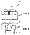
- Figure 3 illustrates a second stopper 32 which is adapted to fit snugly over the bi-directionally valved stopper 3.
- the second stopper 32 has a non return valve 33 and a retaining clip 34 which is designed to engage under the neck 35 of a bottle 2.
- This stopper is to be used in a second operation to be carried out for the preservation of sparkling wines, which will now be described with reference once more to Figure 1.
- the stopper 32 is secured over the bi-directionally valved stopper 3.
- the bottle and stopper are offered up to a second socket 20, which utilises a strike plate 21 and a switch 22 in a similar manner to that described previously.
- Activating the switch 22 causes the relays 11a, 11b, 11c, to open a solenoid valve 23 allowing carbon dioxide to be supplied via the socket 20 and the stoppers 3, 32.
- the amber neon bulb 7 lights, up.
- Carbon dioxide is supplied from a remote source 24 (not shown) and is pumped into the bottle 2, via a third pneumatic circuit until a third pressure sensor 25 detects that a third predetermined pressure has been achieved.
- the relays 11a, 11b, 11c serve to close the solenoid valve 23, closing the third pneumatic circuit and cutting of the supply of carbon dioxide.
- the amber neon bulb 7 goes out and the green neon bulb 15 lights up.
- Removing the bottle 2 causes the switch 22 to return to the off position.
- the green neon bulb 15 goes out and the apparatus is reset.
Landscapes
- Chemical & Material Sciences (AREA)
- Organic Chemistry (AREA)
- Engineering & Computer Science (AREA)
- Health & Medical Sciences (AREA)
- General Engineering & Computer Science (AREA)
- Life Sciences & Earth Sciences (AREA)
- Biochemistry (AREA)
- Bioinformatics & Cheminformatics (AREA)
- Food Science & Technology (AREA)
- General Health & Medical Sciences (AREA)
- Genetics & Genomics (AREA)
- Toxicology (AREA)
- Wood Science & Technology (AREA)
- Zoology (AREA)
- Devices For Dispensing Beverages (AREA)
- Distillation Of Fermentation Liquor, Processing Of Alcohols, Vinegar And Beer (AREA)
- Tea And Coffee (AREA)
Abstract
Description
- This invention relates to preservation of the contents of beverage containers, in particular to preserving the contents of still and sparkling wine bottles once some of the wine has been removed. However, the invention can equally well be used with other beverages and other type of containers, for example wine barrels.
- It is known to preserve still wine in wine bottles by evacuating the air space above the liquid once some of the wine has been consumed. It is also known to preserve sparkling wine in wine bottles by pumping air or carbon dioxide into the bottle to prevent the wine from losing its sparkle.
- Japanese Patent Abstract JP2001354206 discloses an apparatus for extracting and supplying gas from and to a beverage container, respectively.
- However, a problem with such known systems is that the residual air (and hence oxygen) in the bottle allows some oxidation of the contents to occur. Furthermore, some beverages may deteriorate if kept at a sub atmospheric pressure for a sufficient length of time.
- This invention seeks to reduce the amount of residual oxygen in a beverage container in order to increase the length of time for which a preserved beverage may be stored, and seeks to avoid the need to store a beverage at a sub atmospheric pressure.
- In its broadest aspect, the invention provides apparatus for preserving the contents of a part filled container, the apparatus comprising a stopper with a bi-directional valve, adapted to be removably fitted in an aperture of the container; means for extracting a gas from the container, through the valve in the stopper; and means for introducing a gas into the container, through the valve in the stopper.
- The invention also provides an apparatus for preserving the contents of a part filled container, the apparatus comprising a bi-directional valved stopper, adapted to be removably fitted in an aperture of the container; a vacuum source communicating with a socket of the apparatus via a first pneumatic circuit, the socket being adapted to form a seal with the stopper, the vacuum source being arranged, in operation, to remove gas from the container via the stopper to create a sub atmospheric pressure inside the container; means for disconnecting the vacuum source once a first predetermined pressure has been achieved inside the container; an inert gas source communicating with the socket via a second pneumatic circuit, the inert gas source being arranged to supply inert gas into the container via the stopper once the vacuum source has been disconnected; and means for ceasing the supply of inert gas once a second predetermined pressure has been achieved inside the container.
- The vacuum source is preferably a vacuum pump, and the means for disconnecting the vacuum source may comprise a switch which switches off and stops operation of the pump.
- By replacing air, and its oxygen content with an inert gas in a part filled container it is possible to slow the rate of oxidation and hence deterioration of the contents. As the percentage of oxygen in air is known (approximately 18%) and the percentage of remaining air/gas at the first predetermined pressure is known, it is possible to quantify the residual oxygen content after a cycle of removal of gas followed by supply of the inert gas. Two or more cycles may be completed in order to further dilute the residual oxygen content and therefore further increase the possible period of preservation. Alternatively the level of vacuum (ie the first predetermined pressure) may be increased with the same result.
- In the preferred embodiment of the invention the bi-directional valved stopper is a stopper incorporating a flutter valve. The flutter valve is preferably arranged, once a cycle is complete, to retain a small residual pressure differential between the atmosphere inside the container and the ambient atmosphere outside.
- In the case of still beverages, the pressure inside the bottle will be slightly superatmospheric, so that the slight residual pressure prevents the ingress of air if the container (for example a bottle) is cooled or refrigerated. In other embodiments the stopper could incorporate two non return valves which operate to prevent flow in different directions, for example.
- For the preservation of sparkling beverages it is desirable to apply a superatmospheric pressure to the part filled container in order to prevent the beverage from losing its sparkle. This can be done after replacing air and its oxygen content with an inert gas, thus ensuring that the beverage neither oxidises nor loses its effervescence.
- Therefore, for preservation of sparkling beverages the apparatus further comprises a second gas source communicating with a socket, the second gas source being arranged, in operation, to supply gas into the container via the stopper; and means for ceasing the supply of the gas once a third predetermined pressure is reached.
- It would be possible for the two operations, i.e. the replacement of residual oxygen by an inert gas, and the application of a head pressure to be carried out via the same socket. However, for ease of use by bar staff, in the preferred embodiment there are two sockets one for the replacement of residual oxygen by an inert gas, and a second for the application of a head pressure from a second gas source.
- Before offering a sparkling beverage container to the socket for application of the head pressure it is preferable if a second stopper (designed to fit snugly over the first stopper) is fitted. The second stopper has a retention device to stop it from being blown apart from the first stopper, and a non return valve to allow the head pressure to be applied and retained.
- Argon is a preferred inert gas, because argon is particularly effective for inhibiting the evaporation of any dissolved oxygen present in a liquid in the part filled container. Carbon dioxide is preferred as the gas for creating the head pressure. It would also be possible to use carbon dioxide as the inert gas so that only a single gas supply is required.
- Preferably, the means for stopping the pump from pumping through the valve is also arranged to activate the supply of inert gas. The means for stopping the pump from pumping through the valve and for ceasing the supply of the inert gas or the head pressure gas are conveniently implemented by the use of pressure sensitive switches located in the appropriate pneumatic circuit, and arranged to operate once the appropriate sub atmospheric or super atmospheric pressure is reached.
- Such switches may be arranged to actually stop the pump or supply or they may be arranged to close a valve in the appropriate pneumatic circuit, or both.
- Part of the or each socket can be spring loaded relative to a switch which starts the pump operation or the supply of the second gas so that the socket can be displaced by offering the container to the socket, causing the switch to operate.
- According to a second aspect of the invention there is also provided a method for the preservation of the contents of a part filled beverage container, comprising the steps of removing gas from the container until a first predetermined pressure is achieved; and supplying an inert gas to the container until a second predetermined pressure is achieved.
- The above steps may be performed a number of times in order to repeatedly dilute the amount of residual oxygen remaining in the part filled beverage container.
- This method may be used for the preservation of sparkling beverages by including the further step of supplying a gas under pressure to the container until a third predetermined pressure is reached.
- According to another aspect of the invention, there is provided a stopper for a wine bottle, the stopper having a skirt to seal against the neck of a wine bottle and a bi-directional valve which can open to allow flow through the stopper in either direction when a pressure differential above a threshold level is applied in either direction across the stopper, and which remains closed when a pressure differential below said threshold is applied.
- The bi-directional valve is preferably a flutter valve and the stopper is preferably a one-piece moulded product of an elastomer material, with the lips of the flutter valve being integral with the stopper.
- The invention is particularly intended for and adapted to the preservation of wine contained in conventional glass bottles, and may be installed behind a bar where a selection of wines is available for sale. It is simple for a bar tender to dispense one glassful from a part-consumed bottle, to insert the stopper and offer the bottle up to the apparatus so that the air in the headspace, and its oxygen content, can be evacuated from the bottle.
- Stoppers may be used which are colour coded to indicate the ideal frequency for the replacement of residual oxygen by an inert gas to be performed, in dependence upon the expected turnover of the particular product. For example, black may indicate a fast moving product which requires the operation to be performed once at the end of service. Silver may indicate a product which requires the operation to be performed once after each glass of wine is served, and gold may be used to indicate a product which requires the operation to be performed twice after each glass of wine is served.
- Embodiments of the invention will now be described, by way of example only, with reference to the accompanying drawings in which
- Figure 1 illustrates an apparatus according to the present invention;
- Figure 2 illustrates a stopper for use in the present invention; and
- Figure 3 illustrates a retaining device for use with the present invention.
- Figure 1 illustrates a schematic view of one embodiment of the present invention. The apparatus is set to a ready condition using a
switch 17. Awine bottle 2, from which a glass of wine has been dispensed, is closed with a reusable bi-directionally valved stopper 1 which is inserted into the mouth of thebottle 2. The bottle and stopper are then offered up to asocket 3. The socket is connected to astrike plate 5 for operating a switch 4. Thestrike plate 5 is biased such that a switch 4 is usually in the off position. Upward pressure on thestrike plate 5 triggers the switch 4, which causes avacuum pump 6 to operate and anamber neon bulb 7 to be illuminated. Thevacuum pump 6 serves to withdraw air from the headspace of the part filledbottle 2 through the stopper 1 via a first pneumatic circuit. - The stopper 1 incorporates a flutter valve (see Figure 2). This valve will retain a small pressure differential between its two sides (eg 0.1 - 0.15 bar), irrespective of which side is at a higher pressure and which side is at a lower pressure. The valve will however open to allow flow from one side to the other when a pressure differential above a certain level is applied across the valve.
- A pressure sensor B is arranged to detect a first predetermined pressure, which is a subatmospheric pressure. Once this first predetermined pressure is achieved and detected by the sensor 8 a
solenoid valve 10 is caused to operate to close the first pneumatic circuit.Relays pump 6 and to open asecond solenoid valve 12 in a second pneumatic circuit. Argon is supplied from a remote source 13 (not shown) via thesocket 3 and the stopper 1. In this embodiment of the invention argon is pumped through the second pneumatic circuit, although it would be possible to allow the argon to be drawn through the circuit by the pressure differential which has been created. - A
second pressure sensor 16 is arranged to detect when a second predetermined pressure has been achieved. This second predetermined pressure is just above atmospheric pressure, for example 1.1 to 1.2 bar. Once the second predetermined pressure is achieved therelays solenoid valve 12, which closes the second pneumatic circuit and cuts off the supply of argon. Theamber neon bulb 7 then goes out and agreen neon bulb 15 lights up to indicate operation complete. - In the event that the supply of argon is exhausted the
second pressure sensor 16 does not operate and thegreen neon bulb 15 does not light up. The operator will then know that the operation has not been properly completed. - Removing the
bottle 2 causes the switch 4. to return to the off position. Thegreen neon bulb 15 goes out and the apparatus is reset and ready for the next operation. - When the stopper is removed to allow more of the container contents to be dispensed, there will be a small rush of gas out of the container.
- The flutter valve 31 (Figure 2) is preferably arranged to open inwardly at pressures of 1 ± 0.15 bar and outwardly at ≤ 1 bar.
- Figure 3 illustrates a
second stopper 32 which is adapted to fit snugly over the bi-directionallyvalved stopper 3. Thesecond stopper 32 has anon return valve 33 and a retainingclip 34 which is designed to engage under theneck 35 of abottle 2. - This stopper is to be used in a second operation to be carried out for the preservation of sparkling wines, which will now be described with reference once more to Figure 1.
- The
stopper 32 is secured over the bi-directionallyvalved stopper 3. The bottle and stopper are offered up to asecond socket 20, which utilises astrike plate 21 and aswitch 22 in a similar manner to that described previously. - Activating the
switch 22 causes therelays solenoid valve 23 allowing carbon dioxide to be supplied via thesocket 20 and thestoppers amber neon bulb 7 lights, up. Carbon dioxide is supplied from a remote source 24 (not shown) and is pumped into thebottle 2, via a third pneumatic circuit until athird pressure sensor 25 detects that a third predetermined pressure has been achieved. - Once the third predetermined pressure is achieved the
relays solenoid valve 23, closing the third pneumatic circuit and cutting of the supply of carbon dioxide. Theamber neon bulb 7 goes out and thegreen neon bulb 15 lights up. - Similarly to the previous case, in the event that the supply of carbon dioxide is exhausted the
pressure sensor 25 does not operate and thegreen neon bulb 15 does not light up. - Removing the
bottle 2 causes theswitch 22 to return to the off position. Thegreen neon bulb 15 goes out and the apparatus is reset.
Claims (14)
- Apparatus for preserving the contents of a part filled container, the apparatus comprising
a stopper with a bi-directional valve, adapted to be removably fitted in an aperture of the container;
means for extracting a gas from the container, through the valve in the stopper; and
means for introducing a gas into the container, through the valve in the stopper. - Apparatus for preserving the contents of a part filled container, the apparatus comprising
a bi-directional valved stopper, adapted to be removably fitted in an aperture of the container;
a vacuum source communicating with a socket of the apparatus via a first pneumatic circuit, the socket being adapted to form a seal with the stopper, the vacuum source being arranged, in operation, to remove gas from the container via the stopper to create a sub atmospheric pressure inside the container;
means for disconnecting the vacuum source once a first predetermined pressure has been achieved inside the container;
an inert gas source communicating with the socket via a second pneumatic circuit, the inert gas source being arranged to supply inert gas into the container via the stopper once the vacuum source has been disconnected; and
means for ceasing the supply of inert gas once a second predetermined pressure has been achieved inside the container. - Apparatus as claimed in Claim 2, wherein the vacuum source is a vacuum pump, and the means for disconnecting the vacuum source comprises a switch which switches off and stops operation of the pump.
- Apparatus according to Claim 2 or Claim 3, in which the bi-directional valved stopper is a stopper incorporating a flutter valve.
- Apparatus according to any one of Claims 2 to 4, further comprising
a second gas source communicating with a socket, the second gas source being arranged, in operation, to supply a second gas into the container via the stopper; and
means for ceasing the supply of the second gas once a third predetermined pressure is reached. - Apparatus according to Claim 5, further comprising a second stopper adapted to fit over the bi-directional valved stopper, the second stopper having a non return valve and a retention device.
- Apparatus according to any one of Claims 2 to 6, in which the inert gas is argon.
- Apparatus according to any one of Claims 2 to 7, in which the means for stopping the pump is arranged to activate the supply of inert gas.
- Apparatus according to any one of Claims 2 to 8, further comprising a switch biased in the off position by a spring which is in communication with a socket and in which the socket can be displaced against the action of the spring by introduction of the container having the stopper fitted in an aperture, and wherein the displacement of the socket operates the switch to start the pump pumping through the valve.
- Apparatus according to any one of Claims 2 to 9, further comprising a switch biased in the off position by a spring which is in communication with a socket and in which the socket can be displaced against the action of the spring by introduction of the container having the stopper fitted in an aperture, and wherein the displacement of the socket operates the switch to start the supply of the second gas.
- A method for the preservation of the contents of a part filled beverage container, comprising the steps of
removing gas from the container until a first predetermined pressure is achieved; and
supplying an inert gas to the container until a second predetermined pressure is achieved. - A method according to Claim 11, further comprising the step of supplying a second gas to the container until a third predetermined pressure is reached.
- A stopper for a wine bottle, the stopper having a skirt to seal against the neck of a wine bottle and a bi-directional valve which can open to allow flow through the stopper in either direction when a pressure differential above a threshold level is applied in either direction across the stopper, and which remains closed when a pressure differential below said threshold is applied.
- A stopper as claimed in Claim 13, wherein the bi-directional valve is a flutter valve.
Applications Claiming Priority (3)
| Application Number | Priority Date | Filing Date | Title |
|---|---|---|---|
| GBGB0220531.8A GB0220531D0 (en) | 2002-09-04 | 2002-09-04 | Method amd apparatus for preserving the contents of beverage containers |
| GB0220531 | 2002-09-04 | ||
| PCT/GB2003/003757 WO2004022695A1 (en) | 2002-09-04 | 2003-08-29 | Method and apparatus for preserving the contents of beverage containers |
Publications (2)
| Publication Number | Publication Date |
|---|---|
| EP1534816A1 EP1534816A1 (en) | 2005-06-01 |
| EP1534816B1 true EP1534816B1 (en) | 2006-04-05 |
Family
ID=9943476
Family Applications (1)
| Application Number | Title | Priority Date | Filing Date |
|---|---|---|---|
| EP03793860A Expired - Lifetime EP1534816B1 (en) | 2002-09-04 | 2003-08-29 | Method and apparatus for preserving the contents of beverage containers |
Country Status (11)
| Country | Link |
|---|---|
| US (1) | US20060102659A1 (en) |
| EP (1) | EP1534816B1 (en) |
| AT (1) | ATE322537T1 (en) |
| AU (1) | AU2003260758B2 (en) |
| CA (1) | CA2497713A1 (en) |
| DE (1) | DE60304483T2 (en) |
| ES (1) | ES2262012T3 (en) |
| GB (1) | GB0220531D0 (en) |
| NZ (1) | NZ538786A (en) |
| PT (1) | PT1534816E (en) |
| WO (1) | WO2004022695A1 (en) |
Cited By (2)
| Publication number | Priority date | Publication date | Assignee | Title |
|---|---|---|---|---|
| IT201800001032A1 (en) * | 2018-01-16 | 2019-07-16 | Alberto Fabbro | WINE STORAGE METHOD AND CAP FOR IMPLEMENTING THE METHOD |
| WO2021152283A1 (en) | 2020-01-29 | 2021-08-05 | Bermar (International) Ltd. | System and method for preserving the contents of beverage containers |
Families Citing this family (11)
| Publication number | Priority date | Publication date | Assignee | Title |
|---|---|---|---|---|
| US20050142260A1 (en) * | 2003-12-24 | 2005-06-30 | Jonathan Chen | Wine preservation system |
| US8123086B2 (en) | 2004-02-25 | 2012-02-28 | Vinum Corporation | Reusable bottle stopper |
| ES2409181T3 (en) * | 2007-11-28 | 2013-06-25 | Winefit S.R.L. | Device that allows serving from a bottle |
| US20100005811A1 (en) * | 2008-07-11 | 2010-01-14 | Danene Jaffe | Beverage Preservation, Chilling, and Dispensing System |
| US20140216265A1 (en) * | 2009-06-17 | 2014-08-07 | Jose Luis Godoy Varo | Installation for Customizing Alcoholic Drinks and Fragrances |
| DE102010025122A1 (en) * | 2010-06-25 | 2011-12-29 | Karl Horst Knopf | Inert gas dispenser for preserving e.g. opened wine bottle of beer tapping apparatus in bar, has housing connected with pressure-reducing valve of carbonic acid bottle by gas line, where gas supply pin and manometer are arranged at housing |
| US8919610B2 (en) * | 2013-03-15 | 2014-12-30 | Vinum Corporation | Vacuum bottle stopper for wine and method |
| FR3008680B1 (en) * | 2013-07-18 | 2016-03-11 | Winemania | DEVICE FOR PRESERVING A BEVERAGE AFTER OPENING THE BOTTLE CONTAINING THE SAME |
| US9656847B2 (en) * | 2014-03-14 | 2017-05-23 | Haley's Corker, Inc. | Vacuum bottle stopper for introducing inert gas into a wine container |
| US11317641B2 (en) | 2017-04-19 | 2022-05-03 | Ryan FREDERICKSON | Preservation method |
| US11021311B2 (en) * | 2017-11-03 | 2021-06-01 | Illmatik Concepts Llc | Vacuum container for storage of air sensitive materials |
Family Cites Families (12)
| Publication number | Priority date | Publication date | Assignee | Title |
|---|---|---|---|---|
| US1406380A (en) * | 1920-04-12 | 1922-02-14 | Heath Wilfrid Paul | Process of and means for putting up powdered milk and other food products in a sterile atmosphere |
| US2729381A (en) * | 1952-03-12 | 1956-01-03 | Wiser Jacques Nicolas | Process and devices for the submitting successively of bottles and other receptacles to exhaustion and pressure |
| US4434810A (en) * | 1980-07-14 | 1984-03-06 | Vernay Laboratories, Inc. | Bi-directional pressure relief valve |
| FR2526762B1 (en) * | 1982-05-12 | 1987-11-13 | Veron Pierre | METHOD AND DEVICE FOR FILLING BOTTLES AFTER THEY ARE STARTED |
| US4475576A (en) * | 1982-09-03 | 1984-10-09 | Simon Philip E | Wine preservation system |
| FR2601962A1 (en) * | 1986-02-20 | 1988-01-29 | Couesmes Serge | Device for preservation and dispensing, especially of wine, from bottles lying on their sides |
| DD256315A1 (en) * | 1986-12-29 | 1988-05-04 | Nagema Veb K | METHOD AND DEVICE FOR WASTE-PROOFING OXYGEN-SENSITIVE FLUIDS IN BOTTLES |
| ES2074664T3 (en) * | 1990-09-28 | 1995-09-16 | Bermar Int | CONSERVATIVE APPARATUS OF THE CONTENT OF BEVERAGE CONTAINERS. |
| EP1038949B1 (en) * | 1999-03-16 | 2003-05-02 | Alois Jenny | Installation for the production of an anaerobic, microaerophilic or other atmosphere in a closed interchangeable recipient |
| AU756968B2 (en) * | 1999-08-16 | 2003-01-30 | Cash + Carry Angehrn Ag | Method for the preservation of an opened drink bottle |
| JP4491593B2 (en) * | 2000-06-12 | 2010-06-30 | サンセン工業株式会社 | Liquid storage device |
| FR2819687B1 (en) * | 2001-01-23 | 2003-04-11 | Jean Michel Ernewein | PORTABLE WINE STORAGE AND STORAGE DEVICE |
-
2002
- 2002-09-04 GB GBGB0220531.8A patent/GB0220531D0/en not_active Ceased
-
2003
- 2003-08-29 WO PCT/GB2003/003757 patent/WO2004022695A1/en not_active Application Discontinuation
- 2003-08-29 NZ NZ538786A patent/NZ538786A/en not_active IP Right Cessation
- 2003-08-29 EP EP03793860A patent/EP1534816B1/en not_active Expired - Lifetime
- 2003-08-29 AU AU2003260758A patent/AU2003260758B2/en not_active Ceased
- 2003-08-29 CA CA002497713A patent/CA2497713A1/en not_active Abandoned
- 2003-08-29 DE DE60304483T patent/DE60304483T2/en not_active Expired - Lifetime
- 2003-08-29 ES ES03793860T patent/ES2262012T3/en not_active Expired - Lifetime
- 2003-08-29 PT PT03793860T patent/PT1534816E/en unknown
- 2003-08-29 AT AT03793860T patent/ATE322537T1/en active
- 2003-08-29 US US10/526,456 patent/US20060102659A1/en not_active Abandoned
Cited By (3)
| Publication number | Priority date | Publication date | Assignee | Title |
|---|---|---|---|---|
| IT201800001032A1 (en) * | 2018-01-16 | 2019-07-16 | Alberto Fabbro | WINE STORAGE METHOD AND CAP FOR IMPLEMENTING THE METHOD |
| WO2019142220A1 (en) * | 2018-01-16 | 2019-07-25 | Alberto Fabbro | Preservation method of a wine and cap for implementing the method |
| WO2021152283A1 (en) | 2020-01-29 | 2021-08-05 | Bermar (International) Ltd. | System and method for preserving the contents of beverage containers |
Also Published As
| Publication number | Publication date |
|---|---|
| AU2003260758B2 (en) | 2009-07-23 |
| WO2004022695A1 (en) | 2004-03-18 |
| DE60304483D1 (en) | 2006-05-18 |
| EP1534816A1 (en) | 2005-06-01 |
| ATE322537T1 (en) | 2006-04-15 |
| ES2262012T3 (en) | 2006-11-16 |
| US20060102659A1 (en) | 2006-05-18 |
| PT1534816E (en) | 2006-08-31 |
| CA2497713A1 (en) | 2004-03-18 |
| NZ538786A (en) | 2009-01-31 |
| AU2003260758A1 (en) | 2004-03-29 |
| DE60304483T2 (en) | 2007-05-03 |
| GB0220531D0 (en) | 2002-10-09 |
Similar Documents
| Publication | Publication Date | Title |
|---|---|---|
| EP1534816B1 (en) | Method and apparatus for preserving the contents of beverage containers | |
| US5215129A (en) | Preserving the contents of beverage containers | |
| US7048016B2 (en) | Wine preservation system using a central vacuum | |
| US5458165A (en) | Gas actuator assembly | |
| US7395949B2 (en) | Volumetric displacement dispenser | |
| US20060163290A1 (en) | Volumetric displacement dispenser | |
| JP3780944B2 (en) | Device for preserving the contents of a partially filled beverage bottle and a stopper for the device | |
| EP3071494B1 (en) | Pneumatic multifunctional cap | |
| US20080170963A1 (en) | Wine preservation system | |
| EP0783433B1 (en) | Gas actuator assembly | |
| WO2019142220A1 (en) | Preservation method of a wine and cap for implementing the method | |
| JP4530480B2 (en) | Opened bottled beverage processing device | |
| EP1950173A1 (en) | Closure for containers such as bottles and the like and method of carrying it out | |
| JP3233665U (en) | Beverage container cap, beverage container | |
| ES2053400A1 (en) | Process for preserving sparkling wines once the bottle has been opened | |
| JP2003517403A (en) | Food container with space for holding inert gas | |
| JP2000318794A (en) | Apparatus and method for filling drink | |
| MXPA97002854A (en) | Assembly of actuator of |
Legal Events
| Date | Code | Title | Description |
|---|---|---|---|
| PUAI | Public reference made under article 153(3) epc to a published international application that has entered the european phase |
Free format text: ORIGINAL CODE: 0009012 |
|
| 17P | Request for examination filed |
Effective date: 20050302 |
|
| AK | Designated contracting states |
Kind code of ref document: A1 Designated state(s): AT BE BG CH CY CZ DE DK EE ES FI FR GB GR HU IE IT LI LU MC NL PT RO SE SI SK TR |
|
| AX | Request for extension of the european patent |
Extension state: AL LT LV MK |
|
| GRAP | Despatch of communication of intention to grant a patent |
Free format text: ORIGINAL CODE: EPIDOSNIGR1 |
|
| GRAS | Grant fee paid |
Free format text: ORIGINAL CODE: EPIDOSNIGR3 |
|
| GRAA | (expected) grant |
Free format text: ORIGINAL CODE: 0009210 |
|
| RIN1 | Information on inventor provided before grant (corrected) |
Inventor name: MARR, DAVID THOMAS,C/O BERMAR (INTERNAT.) LTD Inventor name: BERESFROD, RICHARD,C/O BERMAR (INTERNAT.) LTD |
|
| AK | Designated contracting states |
Kind code of ref document: B1 Designated state(s): AT BE BG CH CY CZ DE DK EE ES FI FR GB GR HU IE IT LI LU MC NL PT RO SE SI SK TR |
|
| PG25 | Lapsed in a contracting state [announced via postgrant information from national office to epo] |
Ref country code: CZ Free format text: LAPSE BECAUSE OF FAILURE TO SUBMIT A TRANSLATION OF THE DESCRIPTION OR TO PAY THE FEE WITHIN THE PRESCRIBED TIME-LIMIT Effective date: 20060405 Ref country code: FI Free format text: LAPSE BECAUSE OF FAILURE TO SUBMIT A TRANSLATION OF THE DESCRIPTION OR TO PAY THE FEE WITHIN THE PRESCRIBED TIME-LIMIT Effective date: 20060405 Ref country code: RO Free format text: LAPSE BECAUSE OF FAILURE TO SUBMIT A TRANSLATION OF THE DESCRIPTION OR TO PAY THE FEE WITHIN THE PRESCRIBED TIME-LIMIT Effective date: 20060405 Ref country code: SI Free format text: LAPSE BECAUSE OF FAILURE TO SUBMIT A TRANSLATION OF THE DESCRIPTION OR TO PAY THE FEE WITHIN THE PRESCRIBED TIME-LIMIT Effective date: 20060405 Ref country code: SK Free format text: LAPSE BECAUSE OF FAILURE TO SUBMIT A TRANSLATION OF THE DESCRIPTION OR TO PAY THE FEE WITHIN THE PRESCRIBED TIME-LIMIT Effective date: 20060405 |
|
| REG | Reference to a national code |
Ref country code: GB Ref legal event code: FG4D |
|
| RIN1 | Information on inventor provided before grant (corrected) |
Inventor name: BERRESFROD, RICHARD,C/O BERMAR (INTERNAT.) LTD Inventor name: MARR, DAVID THOMAS,C/O BERMAR (INTERNAT.) LTD |
|
| REG | Reference to a national code |
Ref country code: CH Ref legal event code: EP |
|
| REG | Reference to a national code |
Ref country code: IE Ref legal event code: FG4D |
|
| REF | Corresponds to: |
Ref document number: 60304483 Country of ref document: DE Date of ref document: 20060518 Kind code of ref document: P |
|
| PG25 | Lapsed in a contracting state [announced via postgrant information from national office to epo] |
Ref country code: DK Free format text: LAPSE BECAUSE OF FAILURE TO SUBMIT A TRANSLATION OF THE DESCRIPTION OR TO PAY THE FEE WITHIN THE PRESCRIBED TIME-LIMIT Effective date: 20060705 Ref country code: SE Free format text: LAPSE BECAUSE OF FAILURE TO SUBMIT A TRANSLATION OF THE DESCRIPTION OR TO PAY THE FEE WITHIN THE PRESCRIBED TIME-LIMIT Effective date: 20060705 |
|
| PG25 | Lapsed in a contracting state [announced via postgrant information from national office to epo] |
Ref country code: MC Free format text: LAPSE BECAUSE OF NON-PAYMENT OF DUE FEES Effective date: 20060831 |
|
| REG | Reference to a national code |
Ref country code: PT Ref legal event code: SC4A Effective date: 20060629 |
|
| REG | Reference to a national code |
Ref country code: CH Ref legal event code: NV Representative=s name: RITSCHER & PARTNER AG |
|
| REG | Reference to a national code |
Ref country code: ES Ref legal event code: FG2A Ref document number: 2262012 Country of ref document: ES Kind code of ref document: T3 |
|
| ET | Fr: translation filed | ||
| PLBE | No opposition filed within time limit |
Free format text: ORIGINAL CODE: 0009261 |
|
| STAA | Information on the status of an ep patent application or granted ep patent |
Free format text: STATUS: NO OPPOSITION FILED WITHIN TIME LIMIT |
|
| 26N | No opposition filed |
Effective date: 20070108 |
|
| REG | Reference to a national code |
Ref country code: CH Ref legal event code: PCAR Free format text: RITSCHER & PARTNER AG;RESIRAIN 1;8125 ZOLLIKERBERG (CH) |
|
| PG25 | Lapsed in a contracting state [announced via postgrant information from national office to epo] |
Ref country code: GR Free format text: LAPSE BECAUSE OF FAILURE TO SUBMIT A TRANSLATION OF THE DESCRIPTION OR TO PAY THE FEE WITHIN THE PRESCRIBED TIME-LIMIT Effective date: 20060706 |
|
| PG25 | Lapsed in a contracting state [announced via postgrant information from national office to epo] |
Ref country code: BG Free format text: LAPSE BECAUSE OF FAILURE TO SUBMIT A TRANSLATION OF THE DESCRIPTION OR TO PAY THE FEE WITHIN THE PRESCRIBED TIME-LIMIT Effective date: 20060705 Ref country code: EE Free format text: LAPSE BECAUSE OF FAILURE TO SUBMIT A TRANSLATION OF THE DESCRIPTION OR TO PAY THE FEE WITHIN THE PRESCRIBED TIME-LIMIT Effective date: 20060405 |
|
| PG25 | Lapsed in a contracting state [announced via postgrant information from national office to epo] |
Ref country code: TR Free format text: LAPSE BECAUSE OF FAILURE TO SUBMIT A TRANSLATION OF THE DESCRIPTION OR TO PAY THE FEE WITHIN THE PRESCRIBED TIME-LIMIT Effective date: 20060405 Ref country code: HU Free format text: LAPSE BECAUSE OF FAILURE TO SUBMIT A TRANSLATION OF THE DESCRIPTION OR TO PAY THE FEE WITHIN THE PRESCRIBED TIME-LIMIT Effective date: 20061006 Ref country code: LU Free format text: LAPSE BECAUSE OF NON-PAYMENT OF DUE FEES Effective date: 20060829 |
|
| PG25 | Lapsed in a contracting state [announced via postgrant information from national office to epo] |
Ref country code: CY Free format text: LAPSE BECAUSE OF FAILURE TO SUBMIT A TRANSLATION OF THE DESCRIPTION OR TO PAY THE FEE WITHIN THE PRESCRIBED TIME-LIMIT Effective date: 20060405 |
|
| PGFP | Annual fee paid to national office [announced via postgrant information from national office to epo] |
Ref country code: AT Payment date: 20110928 Year of fee payment: 9 |
|
| PGFP | Annual fee paid to national office [announced via postgrant information from national office to epo] |
Ref country code: IE Payment date: 20120824 Year of fee payment: 10 |
|
| PGFP | Annual fee paid to national office [announced via postgrant information from national office to epo] |
Ref country code: BE Payment date: 20120820 Year of fee payment: 10 |
|
| PGFP | Annual fee paid to national office [announced via postgrant information from national office to epo] |
Ref country code: PT Payment date: 20120301 Year of fee payment: 10 Ref country code: NL Payment date: 20120809 Year of fee payment: 10 |
|
| REG | Reference to a national code |
Ref country code: AT Ref legal event code: MM01 Ref document number: 322537 Country of ref document: AT Kind code of ref document: T Effective date: 20120829 |
|
| PG25 | Lapsed in a contracting state [announced via postgrant information from national office to epo] |
Ref country code: AT Free format text: LAPSE BECAUSE OF NON-PAYMENT OF DUE FEES Effective date: 20120829 |
|
| REG | Reference to a national code |
Ref country code: CH Ref legal event code: PFA Owner name: BERMAR INTERNATIONAL LIMITED, GB Free format text: FORMER OWNER: BERMAR INTERNATIONAL LIMITED, GB |
|
| BERE | Be: lapsed |
Owner name: *BERMAR INTERNATIONAL LTD Effective date: 20130831 |
|
| REG | Reference to a national code |
Ref country code: PT Ref legal event code: MM4A Free format text: LAPSE DUE TO NON-PAYMENT OF FEES Effective date: 20140228 |
|
| REG | Reference to a national code |
Ref country code: NL Ref legal event code: V1 Effective date: 20140301 |
|
| PG25 | Lapsed in a contracting state [announced via postgrant information from national office to epo] |
Ref country code: NL Free format text: LAPSE BECAUSE OF NON-PAYMENT OF DUE FEES Effective date: 20140301 |
|
| REG | Reference to a national code |
Ref country code: IE Ref legal event code: MM4A |
|
| PG25 | Lapsed in a contracting state [announced via postgrant information from national office to epo] |
Ref country code: BE Free format text: LAPSE BECAUSE OF NON-PAYMENT OF DUE FEES Effective date: 20130831 |
|
| PG25 | Lapsed in a contracting state [announced via postgrant information from national office to epo] |
Ref country code: PT Free format text: LAPSE BECAUSE OF NON-PAYMENT OF DUE FEES Effective date: 20140228 |
|
| PG25 | Lapsed in a contracting state [announced via postgrant information from national office to epo] |
Ref country code: IE Free format text: LAPSE BECAUSE OF NON-PAYMENT OF DUE FEES Effective date: 20130829 |
|
| REG | Reference to a national code |
Ref country code: FR Ref legal event code: PLFP Year of fee payment: 14 |
|
| REG | Reference to a national code |
Ref country code: FR Ref legal event code: PLFP Year of fee payment: 15 |
|
| REG | Reference to a national code |
Ref country code: FR Ref legal event code: PLFP Year of fee payment: 16 |
|
| PGFP | Annual fee paid to national office [announced via postgrant information from national office to epo] |
Ref country code: DE Payment date: 20190703 Year of fee payment: 17 |
|
| PGFP | Annual fee paid to national office [announced via postgrant information from national office to epo] |
Ref country code: CH Payment date: 20190711 Year of fee payment: 17 |
|
| REG | Reference to a national code |
Ref country code: DE Ref legal event code: R119 Ref document number: 60304483 Country of ref document: DE |
|
| REG | Reference to a national code |
Ref country code: CH Ref legal event code: PL |
|
| PG25 | Lapsed in a contracting state [announced via postgrant information from national office to epo] |
Ref country code: LI Free format text: LAPSE BECAUSE OF NON-PAYMENT OF DUE FEES Effective date: 20200831 Ref country code: CH Free format text: LAPSE BECAUSE OF NON-PAYMENT OF DUE FEES Effective date: 20200831 |
|
| PG25 | Lapsed in a contracting state [announced via postgrant information from national office to epo] |
Ref country code: DE Free format text: LAPSE BECAUSE OF NON-PAYMENT OF DUE FEES Effective date: 20210302 |
|
| PGFP | Annual fee paid to national office [announced via postgrant information from national office to epo] |
Ref country code: FR Payment date: 20210706 Year of fee payment: 19 Ref country code: IT Payment date: 20210721 Year of fee payment: 19 |
|
| PGFP | Annual fee paid to national office [announced via postgrant information from national office to epo] |
Ref country code: ES Payment date: 20210902 Year of fee payment: 19 |
|
| PGFP | Annual fee paid to national office [announced via postgrant information from national office to epo] |
Ref country code: GB Payment date: 20220808 Year of fee payment: 20 |
|
| PG25 | Lapsed in a contracting state [announced via postgrant information from national office to epo] |
Ref country code: IT Free format text: LAPSE BECAUSE OF NON-PAYMENT OF DUE FEES Effective date: 20220829 Ref country code: FR Free format text: LAPSE BECAUSE OF NON-PAYMENT OF DUE FEES Effective date: 20220831 |
|
| REG | Reference to a national code |
Ref country code: GB Ref legal event code: PE20 Expiry date: 20230828 |
|
| REG | Reference to a national code |
Ref country code: ES Ref legal event code: FD2A Effective date: 20231002 |
|
| PG25 | Lapsed in a contracting state [announced via postgrant information from national office to epo] |
Ref country code: GB Free format text: LAPSE BECAUSE OF EXPIRATION OF PROTECTION Effective date: 20230828 Ref country code: ES Free format text: LAPSE BECAUSE OF NON-PAYMENT OF DUE FEES Effective date: 20220830 |