EP1534455B2 - Method and apparatus for locating non-visible objects - Google Patents
Method and apparatus for locating non-visible objects Download PDFInfo
- Publication number
- EP1534455B2 EP1534455B2 EP03787919A EP03787919A EP1534455B2 EP 1534455 B2 EP1534455 B2 EP 1534455B2 EP 03787919 A EP03787919 A EP 03787919A EP 03787919 A EP03787919 A EP 03787919A EP 1534455 B2 EP1534455 B2 EP 1534455B2
- Authority
- EP
- European Patent Office
- Prior art keywords
- array
- machining guide
- sensors
- base member
- relative
- Prior art date
- Legal status (The legal status is an assumption and is not a legal conclusion. Google has not performed a legal analysis and makes no representation as to the accuracy of the status listed.)
- Expired - Lifetime
Links
- 238000000034 method Methods 0.000 title claims description 12
- 238000003754 machining Methods 0.000 claims abstract description 31
- 230000005355 Hall effect Effects 0.000 claims abstract description 22
- 230000005291 magnetic effect Effects 0.000 claims abstract description 18
- 238000006073 displacement reaction Methods 0.000 claims description 3
- 239000003302 ferromagnetic material Substances 0.000 claims description 3
- 230000004044 response Effects 0.000 claims description 3
- 230000000007 visual effect Effects 0.000 claims description 3
- 238000009877 rendering Methods 0.000 claims description 2
- 230000000704 physical effect Effects 0.000 abstract description 2
- 238000005553 drilling Methods 0.000 description 8
- XEEYBQQBJWHFJM-UHFFFAOYSA-N Iron Chemical compound [Fe] XEEYBQQBJWHFJM-UHFFFAOYSA-N 0.000 description 7
- 238000013459 approach Methods 0.000 description 7
- 238000012545 processing Methods 0.000 description 7
- 238000001514 detection method Methods 0.000 description 4
- 239000000463 material Substances 0.000 description 4
- 238000010586 diagram Methods 0.000 description 3
- 230000005294 ferromagnetic effect Effects 0.000 description 3
- 229910052742 iron Inorganic materials 0.000 description 3
- 229910052751 metal Inorganic materials 0.000 description 3
- 239000002184 metal Substances 0.000 description 3
- 229910000838 Al alloy Inorganic materials 0.000 description 2
- BGPVFRJUHWVFKM-UHFFFAOYSA-N N1=C2C=CC=CC2=[N+]([O-])C1(CC1)CCC21N=C1C=CC=CC1=[N+]2[O-] Chemical compound N1=C2C=CC=CC2=[N+]([O-])C1(CC1)CCC21N=C1C=CC=CC1=[N+]2[O-] BGPVFRJUHWVFKM-UHFFFAOYSA-N 0.000 description 2
- 229910045601 alloy Inorganic materials 0.000 description 2
- 239000000956 alloy Substances 0.000 description 2
- 238000010276 construction Methods 0.000 description 2
- 238000004519 manufacturing process Methods 0.000 description 2
- 238000005192 partition Methods 0.000 description 2
- 241000726103 Atta Species 0.000 description 1
- OKTJSMMVPCPJKN-UHFFFAOYSA-N Carbon Chemical compound [C] OKTJSMMVPCPJKN-UHFFFAOYSA-N 0.000 description 1
- 230000032683 aging Effects 0.000 description 1
- 239000004411 aluminium Substances 0.000 description 1
- 229910052782 aluminium Inorganic materials 0.000 description 1
- XAGFODPZIPBFFR-UHFFFAOYSA-N aluminium Chemical compound [Al] XAGFODPZIPBFFR-UHFFFAOYSA-N 0.000 description 1
- 229910052799 carbon Inorganic materials 0.000 description 1
- 238000005253 cladding Methods 0.000 description 1
- 238000004891 communication Methods 0.000 description 1
- 239000002131 composite material Substances 0.000 description 1
- 239000012141 concentrate Substances 0.000 description 1
- 230000003750 conditioning effect Effects 0.000 description 1
- 238000007796 conventional method Methods 0.000 description 1
- 238000012937 correction Methods 0.000 description 1
- 238000013481 data capture Methods 0.000 description 1
- 230000006866 deterioration Effects 0.000 description 1
- 238000011156 evaluation Methods 0.000 description 1
- 239000000835 fiber Substances 0.000 description 1
- 238000010297 mechanical methods and process Methods 0.000 description 1
- 230000005226 mechanical processes and functions Effects 0.000 description 1
- 239000002991 molded plastic Substances 0.000 description 1
- 238000003032 molecular docking Methods 0.000 description 1
- 238000012544 monitoring process Methods 0.000 description 1
- 239000004033 plastic Substances 0.000 description 1
- 229920003023 plastic Polymers 0.000 description 1
- 108090000623 proteins and genes Proteins 0.000 description 1
- 230000004043 responsiveness Effects 0.000 description 1
- 238000010079 rubber tapping Methods 0.000 description 1
- 230000035945 sensitivity Effects 0.000 description 1
Images


Classifications
-
- G—PHYSICS
- G01—MEASURING; TESTING
- G01V—GEOPHYSICS; GRAVITATIONAL MEASUREMENTS; DETECTING MASSES OR OBJECTS; TAGS
- G01V3/00—Electric or magnetic prospecting or detecting; Measuring magnetic field characteristics of the earth, e.g. declination, deviation
- G01V3/15—Electric or magnetic prospecting or detecting; Measuring magnetic field characteristics of the earth, e.g. declination, deviation specially adapted for use during transport, e.g. by a person, vehicle or boat
-
- B—PERFORMING OPERATIONS; TRANSPORTING
- B21—MECHANICAL METAL-WORKING WITHOUT ESSENTIALLY REMOVING MATERIAL; PUNCHING METAL
- B21J—FORGING; HAMMERING; PRESSING METAL; RIVETING; FORGE FURNACES
- B21J15/00—Riveting
- B21J15/10—Riveting machines
- B21J15/28—Control devices specially adapted to riveting machines not restricted to one of the preceding subgroups
-
- B—PERFORMING OPERATIONS; TRANSPORTING
- B21—MECHANICAL METAL-WORKING WITHOUT ESSENTIALLY REMOVING MATERIAL; PUNCHING METAL
- B21J—FORGING; HAMMERING; PRESSING METAL; RIVETING; FORGE FURNACES
- B21J15/00—Riveting
- B21J15/38—Accessories for use in connection with riveting, e.g. pliers for upsetting; Hand tools for riveting
- B21J15/44—Rivet hole positioners
-
- B—PERFORMING OPERATIONS; TRANSPORTING
- B23—MACHINE TOOLS; METAL-WORKING NOT OTHERWISE PROVIDED FOR
- B23B—TURNING; BORING
- B23B49/00—Measuring or gauging equipment on boring machines for positioning or guiding the drill; Devices for indicating failure of drills during boring; Centering devices for holes to be bored
-
- G—PHYSICS
- G01—MEASURING; TESTING
- G01D—MEASURING NOT SPECIALLY ADAPTED FOR A SPECIFIC VARIABLE; ARRANGEMENTS FOR MEASURING TWO OR MORE VARIABLES NOT COVERED IN A SINGLE OTHER SUBCLASS; TARIFF METERING APPARATUS; MEASURING OR TESTING NOT OTHERWISE PROVIDED FOR
- G01D5/00—Mechanical means for transferring the output of a sensing member; Means for converting the output of a sensing member to another variable where the form or nature of the sensing member does not constrain the means for converting; Transducers not specially adapted for a specific variable
- G01D5/12—Mechanical means for transferring the output of a sensing member; Means for converting the output of a sensing member to another variable where the form or nature of the sensing member does not constrain the means for converting; Transducers not specially adapted for a specific variable using electric or magnetic means
- G01D5/14—Mechanical means for transferring the output of a sensing member; Means for converting the output of a sensing member to another variable where the form or nature of the sensing member does not constrain the means for converting; Transducers not specially adapted for a specific variable using electric or magnetic means influencing the magnitude of a current or voltage
- G01D5/142—Mechanical means for transferring the output of a sensing member; Means for converting the output of a sensing member to another variable where the form or nature of the sensing member does not constrain the means for converting; Transducers not specially adapted for a specific variable using electric or magnetic means influencing the magnitude of a current or voltage using Hall-effect devices
- G01D5/145—Mechanical means for transferring the output of a sensing member; Means for converting the output of a sensing member to another variable where the form or nature of the sensing member does not constrain the means for converting; Transducers not specially adapted for a specific variable using electric or magnetic means influencing the magnitude of a current or voltage using Hall-effect devices influenced by the relative movement between the Hall device and magnetic fields
-
- G—PHYSICS
- G01—MEASURING; TESTING
- G01V—GEOPHYSICS; GRAVITATIONAL MEASUREMENTS; DETECTING MASSES OR OBJECTS; TAGS
- G01V3/00—Electric or magnetic prospecting or detecting; Measuring magnetic field characteristics of the earth, e.g. declination, deviation
- G01V3/08—Electric or magnetic prospecting or detecting; Measuring magnetic field characteristics of the earth, e.g. declination, deviation operating with magnetic or electric fields produced or modified by objects or geological structures or by detecting devices
-
- G—PHYSICS
- G01—MEASURING; TESTING
- G01V—GEOPHYSICS; GRAVITATIONAL MEASUREMENTS; DETECTING MASSES OR OBJECTS; TAGS
- G01V3/00—Electric or magnetic prospecting or detecting; Measuring magnetic field characteristics of the earth, e.g. declination, deviation
- G01V3/08—Electric or magnetic prospecting or detecting; Measuring magnetic field characteristics of the earth, e.g. declination, deviation operating with magnetic or electric fields produced or modified by objects or geological structures or by detecting devices
- G01V3/081—Electric or magnetic prospecting or detecting; Measuring magnetic field characteristics of the earth, e.g. declination, deviation operating with magnetic or electric fields produced or modified by objects or geological structures or by detecting devices the magnetic field is produced by the objects or geological structures
-
- B—PERFORMING OPERATIONS; TRANSPORTING
- B23—MACHINE TOOLS; METAL-WORKING NOT OTHERWISE PROVIDED FOR
- B23B—TURNING; BORING
- B23B2215/00—Details of workpieces
- B23B2215/04—Aircraft components
-
- B—PERFORMING OPERATIONS; TRANSPORTING
- B23—MACHINE TOOLS; METAL-WORKING NOT OTHERWISE PROVIDED FOR
- B23B—TURNING; BORING
- B23B2260/00—Details of constructional elements
- B23B2260/128—Sensors
Definitions
- This invention relates to locating non-visible objects, particularly though not exclusively for the purpose of identifying the position of a non-visible object prior to carrying out a mechanical processing step in the vicinity of the object so located.
- a simple example is to locate the position of a load-bearing member in a partition wall made of a wooden frame to either side of which sheets of plasterboard are attached. If it is desired to fix something to the wall, e.g. using a hook, it is necessary to ensure that the hook, e.g. screwed into the wall, goes into part of the tim ber support rather than into the plasterboard, from which it will be easily removed when a load is applied because plasterboard is not particularly strong. Conventional methods, such as tapping the wall with a knuckle to determine the location of the supporting wooden frame members do not give particularly accurate results and require skill.
- apertures in the skin and the rib or spar need to coincide and this coincidence needs to be particularly accurate since if there is inaccuracy, rivetting may be rendered more difficult, or even impossible and inadequately-fitting or mis-applied rivets can become loosened when the aircraft is in service leading to potentially catastrophic failure. Accordingly, the requirements for accurate matching of the hole in the skin with the hole in the rib or spar are very stringent and the penalty for inadequate accuracy may well be the failure of the finished assembly to meet the required rigorous safety standards, leading to the entire assembly having to be recycled.
- the present invention seeks to provide an apparatus for the detection of a non-visible object, quickly and very accurately. It should be noted that the term "object” as used herein is intended to cover a very wide variety of possibilities, including, in particular, a hole.
- the location of the object behind the opaque surface can be rapidly and easily determined and when the displacement is a minimum, the machining gu ide is then located adjacent the surface at that point of the surface immediately and centrally overlying the object in question.
- the position of the array and machining guide can then be fixed, by locking the array on the surface, whereafter the machining guide, for example a guide tube, can then be used to guide, e.g. a drill to make a hole in the opaque surface precisely located relative to the non-visible object. Locking of the array on to the surface can occur via vacuum pads.
- the present invention accordingly also provides apparatus according to claim 3.
- the base member is preferably adapted to be moved across the surface to enable the machining guide to be aligned with the object.
- the apparatus includes fixing means adapted to lock the relative position of the base member and the object relative to one another.
- the means for analysing includes a visual display means adapted to indicate the location of the object relative to the array of sensors, and accordingly to indicate when the array is positioned with the machining guide associated therewith located closest to the non-visible object.
- the present invention is pa rticularly valuable in the technical area of locating holes, particularly, though not exclusively, in the technical field mentioned above, i.e. in fitt ing an opaque metal skin on to underlying supporting members in aircraft construction. While it is theoretically poss ible to detect the presence of a hole in an underlying spar or strut because the physical properties of the hole differ from that of the surrounding material defining the hole, appropriate sensors can be expensive and the usually necessary alignment and calibration of an array of them can be complex. In this particular application of the method of the present invention, however, a simple and highly effective approach is to put a magnet in the hole itself, or locate one relative to the Hall effect sensors and locate a ferromagnetic material, e.g. a soft iron disc, in the hole.
- a ferromagnetic material e.g. a soft iron disc
- the object to be located behind the opaque skin is a hole in the spar.
- the object may be, fo r example, a magnet located relative to an (unbored) spar using an appropriate jig, so that when e.g. a bore is drilled using the machining guide, it is drilled through both skin and spar, but at the desired position on the spar-
- the array of sensors is customarily a symmetrical array about the machining guide.
- the number and positioning of the sensors in the array may be varied depend ing upon the degree of precision required as well as on the type of sensor.
- a particularly preferred approach is to use a cruciform array of sensors with a plurality of sensors located spaced along the arms of a notional cross, the machining guide then being located at the centre point of the intersection between those arms, as this needs only relatively straightforward data processing of the sensor signals.
- the array may be more complex, e.g. 16 sensors x 16 sensors arranged in a square grid, or one or more concentric circles. The processing of the data set from the sensors may then be more complex, but the accuracy of positional detection may be greater.
- the visual display providing an indication of the location of the object relative to the location of the array is preferably compact and easy to understand.
- a particularly preferred form of display is that of a computer-driven flat display screen on which are represented in appropriate symbolic fashion the location of the object and the location of the machining guide. By moving the array and machining guide, the graphic representations on the screen may be made to coincide.
- the display screen may, for example, form part of a conventional laptop computer, or a hand-held computing device, often referred to as a PDA. In either case, by combining appropriate programming and interface electronics, the signals from the individual sensors in the array may be processed using known techniques to produce the indication on screen.
- the apparatus may include means for temporarily fixing the array in a position on the opaque surface, by atta ching it via actuatable vacuum pads thereto.
- the base carrying the array of sensors is preferably equipped with vacuum pads which can be subjected to reduced pressure at two discrete levels, one level providing a sufficient holding force to attach the base member of the array to the surface sufficiently loosely that it can still be moved around relative the reto, and a stronger holding level at which the base member holding the array of sensors is essentially firmly clamped in fixed position against the opaque surface.
- Vacuum fixation may also be conveniently used to locate a display unit, parti cularly where the display unit is PDA, on a portion of the opaque surface close to the portion under which the object is located. Operating in this way is possible rapidly to locate, e.g. holes in a spar underneath an opaque wing skin to an adequate degree of precision.
- the accuracy of performance of apparatus as just described is clearly susceptible to deterioration on account of sensor ageing.
- This problem can be alleviated by providing, for use with the sensor array, some form of standard template of known responsiveness and having means to enable the base member carrying the sensor array to be accurately and repeatably coordinated to the template.
- the individual sensor responses can be interrogated when the array is positioned on the template and the actual responses compared with those which should theoretically be produced, or which have been produced using the same set-up but in the past, with the current values.
- the programming of the data capture and analysis software may be such as to enable automatic corrections to be applied to compensate for sensor drift or loss of sensitivity.
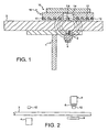
- FIG. 1 this shows in extremely diagrammatic form, how the present invention may be applied to the detection of holes in a spar on the far side of a metal cladding sheet.
- a plate 3 for example an alloy skin for a wing
- the spar is placed against it.
- a magnet assembly 4 set in a suitable mounting is located relative to the hole 2 from below as shown in Figure 1 .
- a sensor array gene rally indicated at 10 This array consists of a base member having a generally flat undersurface in which is set a cruciform array of sixteen Hall effect sensors 12. As seen in the drawing, eight of the sensors 12 are seen spaced to either side of a central sensor 12. The eight are aligned in a row and the central sensor 12 is, counting from the end of the row of sensors perpendicular to the p lane of the drawing, the fourth one.
- Reference number 14 denotes the wall of a cylindrical aperture in the middle of the array.
- the end of the magnet assembly 4 inserted into hole 2 is the centre location of a generally symmetric magnetic field having its maximum located in terms of the upper surface of plate 3 at the point on that upper surface wh ich is precisely aligned with the axis of hole 2. At points on the upper surface of plate 3 more remote from that point, the magnetic field strength is less.
- the magnetic field strength at any point on the surface can be measured using a Hall effect sensor.
- the Hall effect sensors 12 are connected via a suitable signal-carrying cable 16 to an evaluation electronics, for example in the form of a laptop computer or PDA.
- the array 10 is shifted from its position in Figure 1 , the field strengths will vary at the individual sensors 12 and the signals from them can be appropriately analysed to work out how far the axis of aperture 14 then deviates from the axis of hole 2.
- the aperture 14 may be aligned with hole 2 essentially seen from above as shown in Figure 1 .
- Aperture 14 may then, for example, have a drilling guide inserted into it, or, for example, a marking implement of some type so as to identify that point on the upper surface of plate 3 which lies on the axis of hole 2.
- FIG. 2 shows diagrammatically two different ways of operating the system. Each can be used depending on the particular task involved.
- the system shown on the left of the drawing corresponds to the operation as illustrated in Figure 1 , with a magnet 4 one side of an opaque sheet 3, for example an aluminium alloy skin for an aircraft wing, and the Hall effect sensor 12 located on the other.
- a magnet 5 can be located behind the Hall effect sensor 12, with a ferromagnetic diffuser plate 6 located between them.
- the magnetic field below Hall effect sensor 12 as seen in the drawing is affected by a ferromagnetic "target" piece 8 located the other side of skin 3.
- This may be a piece of ferromagnetic material such as soft iron or, for example, a disk or slug of moulded plastics material loaded with iron powder or filings. This latter approach is of particular value in locating holes so that a bo re concentric therewith may be drilled from above as seen in Figure 2 .
- Each hole in e.g.
- an ai rcraft wing spar may- have su ch a plastics slug fitted into it, and these then drop out or are drilled out each time a bore is made through the opaque sheet of material following the location of the hole and fixation of the base member carrying the Hall effect sensor array, the machining guide, and, in this case, the magnets 5.
- th is is a diagrammatic illustration of apparatus in accordance with the invention which is to be used to locate holes 22 in a pre-drilled aircraft wing spar 20 when it is located behind an aluminium skin 21 which is to be fixed to spar 20 by means of rives.
- Each rivet needs to pass through a hole made in skin 21 and through one of the pre-drilled holes 22 in spar 20.
- the apparatus consists basically of a main pneumatics and power supp ly equipment box 30, a movable drilling guide 31 which, as can be seen, is held against the skin 21, and which contains the electronics described below and a display unit at a housing 32.
- Box 30 has a suitable power supply lead 37 for connecting to a source of electrical power.
- an array of Hall effect sensors surround a drilling guide tube 33 in an appropriate arrangement, for example cruciform, though other arrangements can be contemplated.
- Unit 31 also carries a couple of vacuum line switches 34 and 35 which can be actuated by the user of the system to hold unit 31 very firmly against skin 21, i.e. in fixed position relative thereto, and which can be adjusted to release the vacuum slightly so that unit 31 can be moved around on skin 21.
- Umbilical lead 36 provides air and power to unit 31 from box 30.
- a magnet is placed in one of the holes 22 so that a symmetrical magnetic field spreads out through the skin 21 and its field strength can be detected adjacent the surface of skin 21 visible in Figure 2 by mean s of the Hall effect sensors on th e underside of unit 31. Those sensors are connected to processing electronics located in unit 31.
- Display 40 can be a PDA and housing 32 a docking station. Housing 32 may be affixed by means of a suction cup to the visible side of ski n 21 at any convenient point. Fixture is effected by a suction cup actuation lever 41 on housing 32 and the display 40 is connected via a signal cable 44 with the electronics in unit 31. As can be seen on display 40, the display consists of a pair of con centric circles 45, 46 and a (fixed) vertical and horizontal crossbar structure 47.
- the electronics are arranged to show on the screen the position of the point of maximum magnetic field strength.
- the crossbar structure 47 is positioned such that it corresponds to the drilling aperture 33, i.e. as unit 31 is moved, so concentric circles 45 and 46 on the display move likewise. It is accordingly very straightforward, with unit 32 stationary but unit 31 being movable, to move unit 31 into a position where the smaller circle 45 is precisely central relative to the crossbar structure 47. The positioning is easy and intuitive and analogous to align ing the target with the crosshairs in a telescopic rifle sight.
- unit 31 may then be clamped firmly in position on skin 21 and aperture 33 used as a drilling guide enabling a bore to be made in skin 21 which is precisely perpendicular to the surface of skin 21 and which is precisely coincident with the bore 22 in spar 20 which carried the magnet duri ng the positioning process.
- the bore may accordingly be made, unit 31 taken out of the way, a rivet inserted and fixed in position, and the process then repeated for the purpose of drilling the next hole in skin 21 to align with the next aperture 22 in the rib.
- Figure 4 shows a basic diagram of the electronics used in the apparatus shown in Figure 3 .
- the dashed boxes in Figure 4 indicate which parts of the system are housed in unit 31, which on housing 32 and which are housed in box 30.
- An input voltage supply fed via lead 37 is fed via a suitable protection unit against over-voltage and over-current to a power supply unit 50.
- the protection unit 50 protects the power supply denoted 51 from any transients and reverse polarity problems.
- the power supply unit 51 is basically designed to generate stable analogue digital power supplies for use with the Hall effect sensor array in unit 31 and to provide a system voltage for powering the digital processing electronics itself.
- a power supply supervisor unit 52 Located on the output side of power supply unit 51 is a power supply supervisor unit 52 which is used to monitor the sensor voltage supply and to indicate, for example by flashing up a message on display 40, if there is a problem.
- the Hall effect sensor array this is denoted 55 in Figure 3 and the outputs of the individual sensors in the array are fed to a multiplexer 56 and signal conditioning board 57 which is provided with the necessary electronics to clean and stabilise the Hall effect sensor voltage measured.
- the signal corresponding to the voltage selected by multiplexer 56 is fed to a high resolution analogue/digital converter 58 to provide a digital signal corresponding to the Hall effect sensor voltage and this is fed in turn into a digital signal processing unit 59 which stores and processes the digital voltage signals corresponding to each of the Hall effect sensors in turn.
- this can then calculate the position of the centre of the magnetic field relative to the array itself and it can provide that information via a serial communication interface 60 to the display 40 located on housing 32.
- this graphical display presents the position of the sensor array relative to the mag net in a very easily comprehendible fashion.
- the electronics also has an output interface 61 which can be used to cont rol any external apparatus, for example a monitoring computer.
Landscapes
- Engineering & Computer Science (AREA)
- Physics & Mathematics (AREA)
- Life Sciences & Earth Sciences (AREA)
- Remote Sensing (AREA)
- General Physics & Mathematics (AREA)
- Mechanical Engineering (AREA)
- Environmental & Geological Engineering (AREA)
- Geology (AREA)
- General Life Sciences & Earth Sciences (AREA)
- Geophysics (AREA)
- Electromagnetism (AREA)
- Drilling And Boring (AREA)
- Geophysics And Detection Of Objects (AREA)
- Manipulator (AREA)
- Position Fixing By Use Of Radio Waves (AREA)
- Measurement Of Length, Angles, Or The Like Using Electric Or Magnetic Means (AREA)
- Radar Systems Or Details Thereof (AREA)
- Catching Or Destruction (AREA)
- Inorganic Insulating Materials (AREA)
- Crystals, And After-Treatments Of Crystals (AREA)
- Transition And Organic Metals Composition Catalysts For Addition Polymerization (AREA)
Abstract
Description
- This invention relates to locating non-visible objects, particularly though not exclusively for the purpose of identifying the position of a non-visible object prior to carrying out a mechanical processing step in the vicinity of the object so located.
- There are many situations where it is desired to locate something accurately, although the item in question is not visible. A simple example is to locate the position of a load-bearing member in a partition wall made of a wooden frame to either side of which sheets of plasterboard are attached. If it is desired to fix something to the wall, e.g. using a hook, it is necessary to ensure that the hook, e.g. screwed into the wall, goes into part of the tim ber support rather than into the plasterboard, from which it will be easily removed when a load is applied because plasterboard is not particularly strong. Conventional methods, such as tapping the wall with a knuckle to determine the location of the supporting wooden frame members do not give particularly accurate results and require skill. Making a pilot hole through the plasterboard and inserting a piece of bent wire through it into the cavity likewise is not easy to carry out simply, and although location, e.g. using a small magnet, of the usually iron nails which hold the plasterboard to the wooden structure can be employed, again the results tend to be rather inaccurate, although this last approach does have the advantage of avoiding trying to insert a hook where there is already a nail underneath.
US-A-5917314 discloses a capacitative sensing system for finding wall studs, whileUS-A-5434500 describes a system for marking a position on a partition precisely opposite a selected position of the other side against which a magnetic field generator is held. - These systems are useful in the building trades, but are not adapted for use in situations where dimensions are subject to tight tolerance limits, some of wh ich are particularly critical in manufacture. For example, in the manufacture of aircraft, a widely used technique is the application of a metal plate or skin to an underlying frame, for example made of ribs or spars. In order to ensure a firm connection between the skin and the rib or spar, a technique commonly employed is that of fasteni ng the two together, e.g. with a rivet or special fastener. In order to do this, apertures in the skin and the rib or spar need to coincide and this coincidence needs to be particularly accurate since if there is inaccuracy, rivetting may be rendered more difficult, or even impossible and inadequately-fitting or mis-applied rivets can become loosened when the aircraft is in service leading to potentially catastrophic failure. Accordingly, the requirements for accurate matching of the hole in the skin with the hole in the rib or spar are very stringent and the penalty for inadequate accuracy may well be the failure of the finished assembly to meet the required rigorous safety standards, leading to the entire assembly having to be recycled. Although if the rib or spar has pre-formed holes, it is notionally possible to use each of those holes as su ccessive guides for making holes in an applied skin, this is usually awkward and sometimes practically impossible for reasons of space, and inaccuracies creep in. Additionally, drilling a hole through the skin from inside does not always provide accurate alignment of the hole in the skin, so that its axis runs exactly perpendicular to the surface of the skin. This is a particular problem where the skin is varying in thickness, e.g. tapering from a thick to thin section. Working from the outside, however, i.e. working with the skin between the operator and the spar or rib means that the positions of the holes cannot be seen. Attempts to use templates to overcome this have not been successful. Document
EP1132164 discloses a method for installing fasteners in large air frame structures. - The present invention seeks to provide an apparatus for the detection of a non-visible object, quickly and very accurately. It should be noted that the term "object" as used herein is intended to cover a very wide variety of possibilities, including, in particular, a hole.
- Accordingly broadly to the present invention, there is provided a method according to
claim 1. - Using such an approach, the location of the object behind the opaque surface can be rapidly and easily determined and when the displacement is a minimum, the machining gu ide is then located adjacent the surface at that point of the surface immediately and centrally overlying the object in question. The position of the array and machining guide can then be fixed, by locking the array on the surface, whereafter the machining guide, for example a guide tube, can then be used to guide, e.g. a drill to make a hole in the opaque surface precisely located relative to the non-visible object. Locking of the array on to the surface can occur via vacuum pads.
- The present invention accordingly also provides apparatus according to
claim 3. - The base member is preferably adapted to be moved across the surface to enable the machining guide to be aligned with the object. The apparatus includes fixing means adapted to lock the relative position of the base member and the object relative to one another. Preferably the means for analysing includes a visual display means adapted to indicate the location of the object relative to the array of sensors, and accordingly to indicate when the array is positioned with the machining guide associated therewith located closest to the non-visible object.
- The present invention is pa rticularly valuable in the technical area of locating holes, particularly, though not exclusively, in the technical field mentioned above, i.e. in fitt ing an opaque metal skin on to underlying supporting members in aircraft construction. While it is theoretically poss ible to detect the presence of a hole in an underlying spar or strut because the physical properties of the hole differ from that of the surrounding material defining the hole, appropriate sensors can be expensive and the usually necessary alignment and calibration of an array of them can be complex. In this particular application of the method of the present invention, however, a simple and highly effective approach is to put a magnet in the hole itself, or locate one relative to the Hall effect sensors and locate a ferromagnetic material, e.g. a soft iron disc, in the hole.
- Conventional alloys used for aircraft construction are predominantly aluminium alloys which are non-ferromagnetic, so the use of a small cylindrical magnet enables very clear and defined signals to be obtained from an array of Hall effect sensors, even if the skin is thick, e.g. up to 70 mm thick. Other materials may be even thicker - e.g. carbon fibre composites 70 mm or more thick.
- As noted above, the object to be located behind the opaque skin is a hole in the spar. However, the object may be, fo r example, a magnet located relative to an (unbored) spar using an appropriate jig, so that when e.g. a bore is drilled using the machining guide, it is drilled through both skin and spar, but at the desired position on the spar-
- The array of sensors is customarily a symmetrical array about the machining guide. The number and positioning of the sensors in the array may be varied depend ing upon the degree of precision required as well as on the type of sensor. A particularly preferred approach is to use a cruciform array of sensors with a plurality of sensors located spaced along the arms of a notional cross, the machining guide then being located at the centre point of the intersection between those arms, as this needs only relatively straightforward data processing of the sensor signals. However, in appropriate circumstances, the array may be more complex, e.g. 16 sensors x 16 sensors arranged in a square grid, or one or more concentric circles. The processing of the data set from the sensors may then be more complex, but the accuracy of positional detection may be greater.
- The visual display providing an indication of the location of the object relative to the location of the array is preferably compact and easy to understand. A particularly preferred form of display is that of a computer-driven flat display screen on which are represented in appropriate symbolic fashion the location of the object and the location of the machining guide. By moving the array and machining guide, the graphic representations on the screen may be made to coincide. The display screen may, for example, form part of a conventional laptop computer, or a hand-held computing device, often referred to as a PDA. In either case, by combining appropriate programming and interface electronics, the signals from the individual sensors in the array may be processed using known techniques to produce the indication on screen. By appropriate programming, sophisticated features may be introduced rendering the apparatus easier to use, for example automatic re-scaling of the display as the machining guide and object approach coincidence as the array is moved. When the array is first placed on or against the opaque surface, the location of the object may be displayed relative to the location of the entire array, and as the array is moved to bring machining guide and object into close alignment, so the display may be reset automatically to concentrate only on the narrow area around the machining guide, even though the signals from the entire array may still be used as desired to calculate the relative positions of array and object.
- Once coincidence has been achieved by moving the array relative to the object, it is desirable to fix the two tem porarily in position one relative to the other in order to allow the machining guide to be used, e.g. fo r acting as a positioning jig to enable a mechanical process to be carried out on the opaque surface, for example drilling a hole at the position so identified. For this purpose, the apparatus may include means for temporarily fixing the array in a position on the opaque surface, by atta ching it via actuatable vacuum pads thereto.
- The use of vacuum pads is particularly recommended in cases where the opaque surface is not horizontal, a state of affairs often encountered in the assembly of e.g. large aircraft or aircraft components. In such a case, the base carrying the array of sensors is preferably equipped with vacuum pads which can be subjected to reduced pressure at two discrete levels, one level providing a sufficient holding force to attach the base member of the array to the surface sufficiently loosely that it can still be moved around relative the reto, and a stronger holding level at which the base member holding the array of sensors is essentially firmly clamped in fixed position against the opaque surface. Vacuum fixation (or other fixing means) may also be conveniently used to locate a display unit, parti cularly where the display unit is PDA, on a portion of the opaque surface close to the portion under which the object is located. Operating in this way is possible rapidly to locate, e.g. holes in a spar underneath an opaque wing skin to an adequate degree of precision.
- The accuracy of performance of apparatus as just described is clearly susceptible to deterioration on account of sensor ageing. This problem can be alleviated by providing, for use with the sensor array, some form of standard template of known responsiveness and having means to enable the base member carrying the sensor array to be accurately and repeatably coordinated to the template. Using appropriate software programming, the individual sensor responses can be interrogated when the array is positioned on the template and the actual responses compared with those which should theoretically be produced, or which have been produced using the same set-up but in the past, with the current values. The programming of the data capture and analysis software may be such as to enable automatic corrections to be applied to compensate for sensor drift or loss of sensitivity.
- By way of further explanation of the invention, and by way of illustrating how it can be put into practical use, reference is made to the accompanying drawings, in which:
-
Figure 1 is a diagrammatic illustration of a section through a sensor array located adjacent an opaque metallic skin in turn located adjacent a pre-drilled spar; -
Figure 2 is a diagram show ing two alternative approaches to providing the variable strength magnetic field; -
Figure 3 is a diagrammatic perspective view showing apparatus in accordance with the invention in use, and -
Figure 4 is a block diagram showing the electronics arrangements in the apparatus. - Referring to
Figure 1 , this shows in extremely diagrammatic form, how the present invention may be applied to the detection of holes in a spar on the far side of a metal cladding sheet. For the sake of simplicity, only one hole is shown in the flat portion of a spar generally indicated at 1, the hole being denoted 2. As shown, a plate 3 (for example an alloy skin for a wing) which is to be attached to the spar is placed against it. - In order to enable detection of the position of the
hole 2, a magnet assembly 4 set in a suitable mounting is located relative to thehole 2 from below as shown inFigure 1 . - Located on top of
plate 3 as shown inFigure 1 is a sensor array gene rally indicated at 10. This array consists of a base member having a generally flat undersurface in which is set a cruciform array of sixteenHall effect sensors 12. As seen in the drawing, eight of thesensors 12 are seen spaced to either side of acentral sensor 12. The eight are aligned in a row and thecentral sensor 12 is, counting from the end of the row of sensors perpendicular to the p lane of the drawing, the fourth one.Reference number 14 denotes the wall of a cylindrical aperture in the middle of the array. - As wiii be appreciated, the end of the magnet assembly 4 inserted into
hole 2 is the centre location of a generally symmetric magnetic field having its maximum located in terms of the upper surface ofplate 3 at the point on that upper surface wh ich is precisely aligned with the axis ofhole 2. At points on the upper surface ofplate 3 more remote from that point, the magnetic field strength is less. The magnetic field strength at any point on the surface can be measured using a Hall effect sensor. - The
Hall effect sensors 12 are connected via a suitable signal-carryingcable 16 to an evaluation electronics, for example in the form of a laptop computer or PDA. - It will readily be appreciated that if the
array 10 is located as shown inFigure 1 with thehole 14 located coaxially with thehole 2, then the magnetic field strength will be greatest and of equal value at the positions of the Hall sensors radially closest toaperture 14, with the field strength detected by each of the sensors more remote fromaperture 14 being less, and being lowest at the outermost ones. - If the
array 10 is shifted from its position inFigure 1 , the field strengths will vary at theindividual sensors 12 and the signals from them can be appropriately analysed to work out how far the axis ofaperture 14 then deviates from the axis ofhole 2. By movingassembly 10 to minimise that deviation, theaperture 14 may be aligned withhole 2 essentially seen from above as shown inFigure 1 .Aperture 14 may then, for example, have a drilling guide inserted into it, or, for example, a marking implement of some type so as to identify that point on the upper surface ofplate 3 which lies on the axis ofhole 2. -
Figure 2 shows diagrammatically two different ways of operating the system. Each can be used depending on the particular task involved. - The system shown on the left of the drawing corresponds to the operation as illustrated in
Figure 1 , with a magnet 4 one side of anopaque sheet 3, for example an aluminium alloy skin for an aircraft wing, and theHall effect sensor 12 located on the other. - However, the system may also be operated the "other way round", as shown on the right of
Figure 2 . In that alternative, a magnet 5 can be located behind theHall effect sensor 12, with a ferromagnetic diffuser plate 6 located between them. The magnetic field belowHall effect sensor 12 as seen in the drawing is affected by a ferromagnetic "target"piece 8 located the other side ofskin 3. This may be a piece of ferromagnetic material such as soft iron or, for example, a disk or slug of moulded plastics material loaded with iron powder or filings. This latter approach is of particular value in locating holes so that a bo re concentric therewith may be drilled from above as seen inFigure 2 . Each hole in e.g. an ai rcraft wing spar, may- have su ch a plastics slug fitted into it, and these then drop out or are drilled out each time a bore is made through the opaque sheet of material following the location of the hole and fixation of the base member carrying the Hall effect sensor array, the machining guide, and, in this case, the magnets 5. - Referring now to
Figure 3 , th is is a diagrammatic illustration of apparatus in accordance with the invention which is to be used to locateholes 22 in a pre-drilledaircraft wing spar 20 when it is located behind analuminium skin 21 which is to be fixed to spar 20 by means of rives. Each rivet needs to pass through a hole made inskin 21 and through one of thepre-drilled holes 22 inspar 20. - The apparatus consists basically of a main pneumatics and power supp
ly equipment box 30, amovable drilling guide 31 which, as can be seen, is held against theskin 21, and which contains the electronics described below and a display unit at ahousing 32.Box 30 has a suitablepower supply lead 37 for connecting to a source of electrical power. - On the underside of the
unit 31 and accordingly not visible inFigure 2 , is an array of Hall effect sensors. These surround a drilling guide tube 33 in an appropriate arrangement, for example cruciform, though other arrangements can be contemplated. -
Unit 31 also carries a couple of vacuum line switches 34 and 35 which can be actuated by the user of the system to holdunit 31 very firmly againstskin 21, i.e. in fixed position relative thereto, and which can be adjusted to release the vacuum slightly so thatunit 31 can be moved around onskin 21.Umbilical lead 36 provides air and power tounit 31 frombox 30. - Before using the apparatus, to locate one of the
holes 22 not visible behindskin 21, a magnet is placed in one of theholes 22 so that a symmetrical magnetic field spreads out through theskin 21 and its field strength can be detected adjacent the surface ofskin 21 visible inFigure 2 by mean s of the Hall effect sensors on th e underside ofunit 31. Those sensors are connected to processing electronics located inunit 31. - By appropriate processing of the signals received from the individua I Hall effect sensors in the array on the underside of
unit 31, the location of the maximum magnetic field strength point can be found and, more particularly, displayed on asimple screen display 40 set inhousing 32.Display 40 can be a PDA and housing 32 a docking station.Housing 32 may be affixed by means of a suction cup to the visible side ofski n 21 at any convenient point. Fixture is effected by a suctioncup actuation lever 41 onhousing 32 and thedisplay 40 is connected via asignal cable 44 with the electronics inunit 31. As can be seen ondisplay 40, the display consists of a pair of concentric circles horizontal crossbar structure 47. The electronics are arranged to show on the screen the position of the point of maximum magnetic field strength. Thecrossbar structure 47 is positioned such that it corresponds to the drilling aperture 33, i.e. asunit 31 is moved, soconcentric circles unit 32 stationary butunit 31 being movable, to moveunit 31 into a position where thesmaller circle 45 is precisely central relative to thecrossbar structure 47. The positioning is easy and intuitive and analogous to align ing the target with the crosshairs in a telescopic rifle sight. - Once this coincidence has been achieved,
unit 31 may then be clamped firmly in position onskin 21 and aperture 33 used as a drilling guide enabling a bore to be made inskin 21 which is precisely perpendicular to the surface ofskin 21 and which is precisely coincident with thebore 22 inspar 20 which carried the magnet duri ng the positioning process. The bore may accordingly be made,unit 31 taken out of the way, a rivet inserted and fixed in position, and the process then repeated for the purpose of drilling the next hole inskin 21 to align with thenext aperture 22 in the rib. -
Figure 4 shows a basic diagram of the electronics used in the apparatus shown inFigure 3 . - The dashed boxes in
Figure 4 indicate which parts of the system are housed inunit 31, which onhousing 32 and which are housed inbox 30. An input voltage supply fed vialead 37 is fed via a suitable protection unit against over-voltage and over-current to apower supply unit 50. Theprotection unit 50 protects the power supply denoted 51 from any transients and reverse polarity problems. Thepower supply unit 51 is basically designed to generate stable analogue digital power supplies for use with the Hall effect sensor array inunit 31 and to provide a system voltage for powering the digital processing electronics itself. - Located on the output side of
power supply unit 51 is a powersupply supervisor unit 52 which is used to monitor the sensor voltage supply and to indicate, for example by flashing up a message ondisplay 40, if there is a problem. - Turning now to the Hall effect sensor array, this is denoted 55 in
Figure 3 and the outputs of the individual sensors in the array are fed to amultiplexer 56 andsignal conditioning board 57 which is provided with the necessary electronics to clean and stabilise the Hall effect sensor voltage measured. The signal corresponding to the voltage selected bymultiplexer 56 is fed to a high resolution analogue/digital converter 58 to provide a digital signal corresponding to the Hall effect sensor voltage and this is fed in turn into a digitalsignal processing unit 59 which stores and processes the digital voltage signals corresponding to each of the Hall effect sensors in turn. By appropriate programming, this can then calculate the position of the centre of the magnetic field relative to the array itself and it can provide that information via aserial communication interface 60 to thedisplay 40 located onhousing 32. As noted with respect toFigure 3 , this graphical display presents the position of the sensor array relative to the mag net in a very easily comprehendible fashion. - The electronics also has an
output interface 61 which can be used to cont rol any external apparatus, for example a monitoring computer.
Claims (7)
- A method of locating an object lying behind an opaque surface rendering the object non-visible which comprises providing in the neighbourhood of the object a variable strength magnetic field, sensing the magnetic field strength at a plurality of positions relative to the object using an array of Hall effect magnetic sensors, the array of Hall effect sensors being associated geometrically with a machining guide, such that the machining guide and the array of sensors are fixed positionally one relative to the other, interrogating the sensors to determine the value of the field strength at at least the majority of the sensors, analysing the sensor responses to determine the displacement between the object and the machining guide, and moving the array and machining guide to a position in which the displacement is a minimum, such that once the machining guide is located adjacent the surface at that point of the surface immediately and centrally overlying the object in question, the position of the array and machining guide is fixed using a fixing means to ensure said position is fixed during a mechanical operation, characterised in that said fixing is effected by locking the array on to the surface via vacuum pads at one of two levels of holding force, one level providing a sufficient holding force to attach the array and machining guide to the surface sufficiently loosely for the performance of said moving, and a stronger holding level at which the array and machining guide are essentially firmly clamped in fixed position against the opaque surface.
- A method according to Claim 1 wherein the object is a hole relative to which a magnet or body of ferromagnetic material is located.
- Apparatus for locating a non-visible object positioned behind an opaque surface, an object having provided in the neighbourhood thereof a variable strength magnetic field, which apparatus comprises means to generate a variable strength magnetic field, a base member adapted to be placed on or against the surface, means in the base member defining a machining guide, an array of Hall effect sensors located relative to the machining guide, means for collecting and analysing outputs from at least some of the sensors to provide an indication of the variation of the magnetic field associated with the object relative to the position of the base member, and to provide a further indication that the machining guide is located adjacent the surface at that point of the surface immediately and centrally overlying the object in question, and fixing means adapted to lock the position of the base member and the object relative to one another once said further indication has been provided such that the position of the base member is fixed during a mechanical operation, characterised in that said fixing means comprises vacuum pads for locking the base member onto the surface and is operable to provide two levels of holding force, one level providing a sufficient holding force to attach the base member to the surface sufficiently loosely for moving said array and machining guide, and a stronger holding level at which the base member is essentially firmly clamped in fixed position against the opaque surface.
- Apparatus according to Claim 3 wherein the base member is adapted to be moved across the surface to enable the machining guide to be aligned with the object.
- Apparatus according to Claim 3 or Claim 4 wherein the means for analysing includes a visual display means adapted to indicate the location of the object relative to the array of sensors, and accordingly to indicate when the array is positioned with the machining guide associated therewith located closest to the non-visible object.
- Apparatus according to any one of Claims 3 to 5 wherein the array of Hall effect sensors is a cruciform array.
- Apparatus according to any one of Claims 3 to 6 wherein the signal display is a computer-driven flat display screen adapted to represent in approximate symbolic fashion the location of the object and the location of the machining guide.
Priority Applications (1)
| Application Number | Priority Date | Filing Date | Title |
|---|---|---|---|
| EP07015064.4A EP1857206B1 (en) | 2002-08-19 | 2003-08-19 | Method and apparatus for locating non-visible objects |
Applications Claiming Priority (3)
| Application Number | Priority Date | Filing Date | Title |
|---|---|---|---|
| GB0219316 | 2002-08-19 | ||
| GBGB0219316.7A GB0219316D0 (en) | 2002-08-19 | 2002-08-19 | Locating non-visible objects |
| PCT/GB2003/003624 WO2004016380A1 (en) | 2002-08-19 | 2003-08-19 | Method and apparatus for locating non-visible objects |
Related Child Applications (2)
| Application Number | Title | Priority Date | Filing Date |
|---|---|---|---|
| EP07015064.4A Division EP1857206B1 (en) | 2002-08-19 | 2003-08-19 | Method and apparatus for locating non-visible objects |
| EP07015064.4 Division-Into | 2007-08-01 |
Publications (3)
| Publication Number | Publication Date |
|---|---|
| EP1534455A1 EP1534455A1 (en) | 2005-06-01 |
| EP1534455B1 EP1534455B1 (en) | 2008-12-03 |
| EP1534455B2 true EP1534455B2 (en) | 2012-06-27 |
Family
ID=9942601
Family Applications (2)
| Application Number | Title | Priority Date | Filing Date |
|---|---|---|---|
| EP07015064.4A Expired - Lifetime EP1857206B1 (en) | 2002-08-19 | 2003-08-19 | Method and apparatus for locating non-visible objects |
| EP03787919A Expired - Lifetime EP1534455B2 (en) | 2002-08-19 | 2003-08-19 | Method and apparatus for locating non-visible objects |
Family Applications Before (1)
| Application Number | Title | Priority Date | Filing Date |
|---|---|---|---|
| EP07015064.4A Expired - Lifetime EP1857206B1 (en) | 2002-08-19 | 2003-08-19 | Method and apparatus for locating non-visible objects |
Country Status (11)
| Country | Link |
|---|---|
| US (5) | US20060022666A1 (en) |
| EP (2) | EP1857206B1 (en) |
| AT (1) | ATE416057T1 (en) |
| AU (1) | AU2003255812A1 (en) |
| CA (1) | CA2496444C (en) |
| DE (1) | DE60325071D1 (en) |
| DK (1) | DK1534455T4 (en) |
| ES (2) | ES2431665T3 (en) |
| GB (1) | GB0219316D0 (en) |
| PT (1) | PT1534455E (en) |
| WO (1) | WO2004016380A1 (en) |
Families Citing this family (32)
| Publication number | Priority date | Publication date | Assignee | Title |
|---|---|---|---|---|
| GB0219316D0 (en) * | 2002-08-19 | 2002-09-25 | Electronic Ltd Ab | Locating non-visible objects |
| WO2005047823A1 (en) | 2003-11-07 | 2005-05-26 | Bae Systems Plc | Increased precision position sensors |
| GB2438578A (en) * | 2006-05-30 | 2007-12-05 | Cnh Belgium Nv | Metal object detection system for harvester |
| GB2456560B (en) * | 2008-01-18 | 2010-09-08 | Electronic Ltd Ab | Method of securing a fastener |
| GB0820405D0 (en) * | 2008-11-07 | 2008-12-17 | Advanced Analysis And Automati | Alignment system |
| US9244133B2 (en) * | 2011-01-13 | 2016-01-26 | Icove And Associates, Llc | Handheld devices and structures to detect sticky devices having magnets |
| GB2487963A (en) * | 2011-02-10 | 2012-08-15 | Bae Systems Plc | Imaging of hidden objects using a Halbach array of electromagnets |
| FR2980267B1 (en) * | 2011-09-21 | 2013-10-04 | Eads Europ Aeronautic Defence | FOURCAULT CURRENT MEASURING DEVICE AND MACHINE FOR COUNTERPILLING A COMPLEX STRUCTURE COMPRISING SUCH A DEVICE |
| CN103100855A (en) * | 2011-11-14 | 2013-05-15 | 成都飞机工业(集团)有限责任公司 | Method of automatic drilling and riveting of large thin-wall parts |
| US9348001B2 (en) | 2013-10-21 | 2016-05-24 | General Electric Company | Method and system for detecting surface features on turbine components |
| RU2555263C1 (en) * | 2014-01-09 | 2015-07-10 | Федеральное государственное бюджетное образовательное учреждение высшего профессионального образования Казанский национальный исследовательский технический университет им. А.Н. Туполева-КАИ (КНИТУ-КАИ) | Method of riveting of curvilinear panels at drilling-riveting machine |
| US11035672B2 (en) * | 2015-05-12 | 2021-06-15 | The Boeing Company | Sensing of a magnetic target |
| US10589074B2 (en) | 2016-06-30 | 2020-03-17 | Integra Lifesciences Switzerland Sàrl | Magneto-resistive sensor tool set for hydrocephalus valve |
| US10286196B2 (en) | 2016-06-30 | 2019-05-14 | Integra Lifesciences Switzerland Sàrl | Device to control magnetic rotor of a programmable hydrocephalus valve |
| GB201614861D0 (en) | 2016-09-01 | 2016-10-19 | Advanced Analysis And Integration Ltd | Targets for alignment systems |
| FR3063350B1 (en) * | 2017-02-24 | 2021-09-10 | Dassault Aviat | SYSTEM FOR DETERMINING A LOCATION PARAMETER, DETERMINATION METHOD, ASSOCIATED MACHINING UNIT AND MACHINING METHOD |
| US10888692B2 (en) | 2017-09-19 | 2021-01-12 | Integra Lifesciences Switzerland Sàrl | Electronic toolset for use with multiple generations of implantable programmable valves with or without orientation functionality based on a fixed reference magnet |
| US10850081B2 (en) | 2017-09-19 | 2020-12-01 | Integra LifeSciences Switzerland Sáarl | Implantable bodily fluid drainage valve with magnetic field resistance engagement confirmation |
| US10850080B2 (en) | 2017-09-19 | 2020-12-01 | Integra LifeSciences Switzerland Sárl | Electronic toolset to locate, read, adjust, and confirm adjustment in an implantable bodily fluid drainage system without recalibrating following adjustment |
| US10994108B2 (en) | 2017-09-19 | 2021-05-04 | Integra LifeSciences Switzerland Sárl | Programmable drainage valve with fixed reference magnet for determining direction of flow operable with analog or digital compass toolsets |
| US12013264B2 (en) | 2018-10-16 | 2024-06-18 | Kyocera Avx Components (Werne) Gmbh | Position sensing apparatus and method |
| US11555940B2 (en) | 2018-10-31 | 2023-01-17 | KYOCERA AVX Components (Werne), GmbH | Position sensing apparatus and method |
| US11235396B2 (en) | 2019-02-14 | 2022-02-01 | Mtm Robotics, Llc | System and method for self contained through sensor for determining an actuation position for a machine |
| US11003156B2 (en) | 2019-02-14 | 2021-05-11 | Mtm Robotics, Llc | System and method for automated aperture alignment in response to detecting an object |
| US11036201B2 (en) * | 2019-02-14 | 2021-06-15 | Mtm Robotics, Llc | System and method for automation of sensing and machine actuation in a manufacturing environment |
| JP7495715B2 (en) | 2020-05-11 | 2024-06-05 | 株式会社京岡 | Magnetic exploration equipment |
| JP7004788B1 (en) | 2020-11-05 | 2022-01-21 | 住友金属鉱山シポレックス株式会社 | Embedded hardware position detection method and embedded hardware position detection device |
| KR20230059957A (en) * | 2021-10-26 | 2023-05-04 | 삼성디스플레이 주식회사 | Display panel manufacturing apparatus and display panel manufacturing method using the same |
| EP4215951A1 (en) * | 2022-01-21 | 2023-07-26 | PoleDetect Holding ApS | Locating device and system for detecting hidden objects in building constructions |
| CN114719727B (en) * | 2022-03-25 | 2024-06-11 | 四川腾盾科技有限公司 | Aircraft finished product assembling, positioning and detecting method based on magnetic heteropolar attraction |
| CN114812367B (en) * | 2022-04-26 | 2024-09-24 | 北京特倍福电子技术有限公司 | Non-contact external magnetic induction linear displacement measurement method |
| CN120571906B (en) * | 2025-08-05 | 2025-10-10 | 山东众冶集团有限公司 | Cabin door cover edge positioning type stamping device |
Citations (6)
| Publication number | Priority date | Publication date | Assignee | Title |
|---|---|---|---|---|
| DE4404413C1 (en) † | 1994-02-11 | 1995-01-19 | Klessmann Ima Norte Maschfab | Vacuum clamping device |
| US5383751A (en) † | 1993-08-05 | 1995-01-24 | Vought Aircraft Company | Manually positioned computer controlled drilling machine |
| GB2299772A (en) † | 1995-04-11 | 1996-10-16 | Secr Defence | Portable drilling system |
| EP1132164A2 (en) † | 2000-03-09 | 2001-09-12 | The Boeing Company | Apparatus and method for installing fasteners in a workpiece |
| WO2002006003A1 (en) † | 2000-07-19 | 2002-01-24 | Bae Systems Plc | Tool positioning system |
| WO2003095154A1 (en) † | 2002-05-09 | 2003-11-20 | The Boeing Company | Magnetic indexer for high accuracy hole drilling |
Family Cites Families (15)
| Publication number | Priority date | Publication date | Assignee | Title |
|---|---|---|---|---|
| US1971189A (en) | 1933-02-01 | 1934-08-21 | Gen Electric | Magnetic detector |
| US2785592A (en) | 1952-12-23 | 1957-03-19 | Shell Dev | Magnetic position locating and controlling probe and system |
| SE455236B (en) * | 1986-10-17 | 1988-06-27 | Derman Ab K G | DEVICE FOR LOCATING HID DOSES |
| DK77687A (en) * | 1987-02-16 | 1988-08-17 | Ove Larsen | PROCEDURE AND APPARATUS FOR MARKING ABOVE ITEMS ON EACH SIDE OF A PLATE LIKE A BUILDING ELEMENT |
| JPH0756929B2 (en) * | 1990-06-26 | 1995-06-14 | 株式会社村田製作所 | Hybrid circuit |
| US5434500A (en) * | 1993-07-26 | 1995-07-18 | Hauck; Bruce | Magnetic field generator and detector position indicator |
| GB9404416D0 (en) | 1994-03-08 | 1994-04-20 | Turner Intellect Property Ltd | Device for finding concealed studs |
| JPH09257405A (en) | 1996-03-26 | 1997-10-03 | Matsushita Electric Works Ltd | Position detection apparatus for buried object |
| JPH1039040A (en) | 1996-07-22 | 1998-02-13 | Matsushita Electric Works Ltd | Device for detecting position of buried article |
| US5917314A (en) * | 1996-08-08 | 1999-06-29 | Zircon Corporation | Electronic wall-stud sensor with three capacitive elements |
| US5773971A (en) * | 1996-08-08 | 1998-06-30 | Zircon Corporation | Three electrode AC detection |
| US6137281A (en) * | 1998-05-15 | 2000-10-24 | Lockheed Martin Corporation | Magnetic back-to-back locator |
| IT244098Y1 (en) * | 1998-06-26 | 2002-03-07 | Vegas Spa | HIGH-COMFORT SOCK STRUCTURE |
| GB0219316D0 (en) * | 2002-08-19 | 2002-09-25 | Electronic Ltd Ab | Locating non-visible objects |
| US9551628B2 (en) * | 2014-03-31 | 2017-01-24 | Automation Controls & Engineering, LLC | Flexible automation cell for performing secondary operations in concert with a machining center and roll check operations |
-
2002
- 2002-08-19 GB GBGB0219316.7A patent/GB0219316D0/en not_active Ceased
-
2003
- 2003-08-19 AT AT03787919T patent/ATE416057T1/en active
- 2003-08-19 AU AU2003255812A patent/AU2003255812A1/en not_active Abandoned
- 2003-08-19 PT PT03787919T patent/PT1534455E/en unknown
- 2003-08-19 DE DE60325071T patent/DE60325071D1/en not_active Expired - Lifetime
- 2003-08-19 ES ES07015064T patent/ES2431665T3/en not_active Expired - Lifetime
- 2003-08-19 US US10/525,129 patent/US20060022666A1/en not_active Abandoned
- 2003-08-19 ES ES03787919T patent/ES2321507T5/en not_active Expired - Lifetime
- 2003-08-19 WO PCT/GB2003/003624 patent/WO2004016380A1/en not_active Ceased
- 2003-08-19 CA CA2496444A patent/CA2496444C/en not_active Expired - Lifetime
- 2003-08-19 EP EP07015064.4A patent/EP1857206B1/en not_active Expired - Lifetime
- 2003-08-19 DK DK03787919.4T patent/DK1534455T4/en active
- 2003-08-19 EP EP03787919A patent/EP1534455B2/en not_active Expired - Lifetime
-
2007
- 2007-07-31 US US11/831,766 patent/US9453934B2/en active Active
-
2016
- 2016-04-11 US US15/095,756 patent/US9910179B2/en not_active Expired - Lifetime
-
2018
- 2018-03-05 US US15/911,646 patent/US10353105B2/en not_active Expired - Lifetime
-
2019
- 2019-06-20 US US16/446,761 patent/US11448793B2/en not_active Expired - Lifetime
Patent Citations (6)
| Publication number | Priority date | Publication date | Assignee | Title |
|---|---|---|---|---|
| US5383751A (en) † | 1993-08-05 | 1995-01-24 | Vought Aircraft Company | Manually positioned computer controlled drilling machine |
| DE4404413C1 (en) † | 1994-02-11 | 1995-01-19 | Klessmann Ima Norte Maschfab | Vacuum clamping device |
| GB2299772A (en) † | 1995-04-11 | 1996-10-16 | Secr Defence | Portable drilling system |
| EP1132164A2 (en) † | 2000-03-09 | 2001-09-12 | The Boeing Company | Apparatus and method for installing fasteners in a workpiece |
| WO2002006003A1 (en) † | 2000-07-19 | 2002-01-24 | Bae Systems Plc | Tool positioning system |
| WO2003095154A1 (en) † | 2002-05-09 | 2003-11-20 | The Boeing Company | Magnetic indexer for high accuracy hole drilling |
Also Published As
| Publication number | Publication date |
|---|---|
| DE60325071D1 (en) | 2009-01-15 |
| EP1857206B1 (en) | 2013-08-07 |
| AU2003255812A1 (en) | 2004-03-03 |
| DK1534455T4 (en) | 2012-10-08 |
| US9910179B2 (en) | 2018-03-06 |
| EP1534455A1 (en) | 2005-06-01 |
| US9453934B2 (en) | 2016-09-27 |
| US20060022666A1 (en) | 2006-02-02 |
| DK1534455T3 (en) | 2009-04-14 |
| US20160223700A1 (en) | 2016-08-04 |
| CA2496444A1 (en) | 2004-02-26 |
| ES2321507T5 (en) | 2013-01-23 |
| WO2004016380A1 (en) | 2004-02-26 |
| EP1534455B1 (en) | 2008-12-03 |
| US20180259669A1 (en) | 2018-09-13 |
| ES2321507T3 (en) | 2009-06-08 |
| EP1857206A1 (en) | 2007-11-21 |
| US11448793B2 (en) | 2022-09-20 |
| US20190302305A1 (en) | 2019-10-03 |
| PT1534455E (en) | 2009-03-31 |
| CA2496444C (en) | 2013-02-19 |
| ATE416057T1 (en) | 2008-12-15 |
| GB0219316D0 (en) | 2002-09-25 |
| US10353105B2 (en) | 2019-07-16 |
| ES2431665T3 (en) | 2013-11-27 |
| US20080048635A1 (en) | 2008-02-28 |
Similar Documents
| Publication | Publication Date | Title |
|---|---|---|
| EP1534455B1 (en) | Method and apparatus for locating non-visible objects | |
| EP1501658B1 (en) | Magnetic indexer for high accuracy hole drilling | |
| EP2492065B1 (en) | Force and normality sensing for end effector clamp | |
| EP1132164A2 (en) | Apparatus and method for installing fasteners in a workpiece | |
| US20200391330A1 (en) | Fastener For Affixing Magnetic Targets To A Nut Plate For Use In A System For Locating Non-Visible Objects | |
| EP1067359B1 (en) | Part measurement and verification with a hand holdable information processor | |
| CN101094588A (en) | Test clamps | |
| EP4145087A1 (en) | Device and method for calibrating elongated metallurgical tool based on laser ranging sensor | |
| EP1275470B1 (en) | Device for targeted positioning of a hand-held machine tool | |
| US2408595A (en) | Point marker | |
| US11235396B2 (en) | System and method for self contained through sensor for determining an actuation position for a machine | |
| US11003156B2 (en) | System and method for automated aperture alignment in response to detecting an object | |
| EP2703654B1 (en) | Method for fastening composite material component | |
| CN113231664B (en) | Hole position positioning and hole opening device and method for fixed point on airplane frame beam | |
| US11036201B2 (en) | System and method for automation of sensing and machine actuation in a manufacturing environment | |
| CN223034577U (en) | An adjustable positioning tool for embedded parts of cantilever scaffolding | |
| CN223078028U (en) | A scratch test machine | |
| JPS61253507A (en) | Method and device for position teaching of industrial robot or the like |
Legal Events
| Date | Code | Title | Description |
|---|---|---|---|
| PUAI | Public reference made under article 153(3) epc to a published international application that has entered the european phase |
Free format text: ORIGINAL CODE: 0009012 |
|
| 17P | Request for examination filed |
Effective date: 20050318 |
|
| AK | Designated contracting states |
Kind code of ref document: A1 Designated state(s): AT BE BG CH CY CZ DE DK EE ES FI FR GB GR HU IE IT LI LU MC NL PT RO SE SI SK TR |
|
| AX | Request for extension of the european patent |
Extension state: AL LT LV MK |
|
| DAX | Request for extension of the european patent (deleted) | ||
| 17Q | First examination report despatched |
Effective date: 20060718 |
|
| 17Q | First examination report despatched |
Effective date: 20060718 |
|
| GRAP | Despatch of communication of intention to grant a patent |
Free format text: ORIGINAL CODE: EPIDOSNIGR1 |
|
| GRAS | Grant fee paid |
Free format text: ORIGINAL CODE: EPIDOSNIGR3 |
|
| GRAS | Grant fee paid |
Free format text: ORIGINAL CODE: EPIDOSNIGR3 |
|
| GRAA | (expected) grant |
Free format text: ORIGINAL CODE: 0009210 |
|
| AK | Designated contracting states |
Kind code of ref document: B1 Designated state(s): AT BE BG CH CY CZ DE DK EE ES FI FR GB GR HU IE IT LI LU MC NL PT RO SE SI SK TR |
|
| REG | Reference to a national code |
Ref country code: GB Ref legal event code: FG4D |
|
| REG | Reference to a national code |
Ref country code: CH Ref legal event code: EP |
|
| REG | Reference to a national code |
Ref country code: IE Ref legal event code: FG4D |
|
| REF | Corresponds to: |
Ref document number: 60325071 Country of ref document: DE Date of ref document: 20090115 Kind code of ref document: P |
|
| REG | Reference to a national code |
Ref country code: SE Ref legal event code: TRGR Ref country code: PT Ref legal event code: SC4A Free format text: AVAILABILITY OF NATIONAL TRANSLATION Effective date: 20090320 |
|
| REG | Reference to a national code |
Ref country code: DK Ref legal event code: T3 |
|
| REG | Reference to a national code |
Ref country code: CH Ref legal event code: NV Representative=s name: SERVOPATENT GMBH |
|
| PG25 | Lapsed in a contracting state [announced via postgrant information from national office to epo] |
Ref country code: SI Free format text: LAPSE BECAUSE OF FAILURE TO SUBMIT A TRANSLATION OF THE DESCRIPTION OR TO PAY THE FEE WITHIN THE PRESCRIBED TIME-LIMIT Effective date: 20081203 |
|
| REG | Reference to a national code |
Ref country code: ES Ref legal event code: FG2A Ref document number: 2321507 Country of ref document: ES Kind code of ref document: T3 |
|
| PG25 | Lapsed in a contracting state [announced via postgrant information from national office to epo] |
Ref country code: RO Free format text: LAPSE BECAUSE OF FAILURE TO SUBMIT A TRANSLATION OF THE DESCRIPTION OR TO PAY THE FEE WITHIN THE PRESCRIBED TIME-LIMIT Effective date: 20081203 Ref country code: EE Free format text: LAPSE BECAUSE OF FAILURE TO SUBMIT A TRANSLATION OF THE DESCRIPTION OR TO PAY THE FEE WITHIN THE PRESCRIBED TIME-LIMIT Effective date: 20081203 Ref country code: BG Free format text: LAPSE BECAUSE OF FAILURE TO SUBMIT A TRANSLATION OF THE DESCRIPTION OR TO PAY THE FEE WITHIN THE PRESCRIBED TIME-LIMIT Effective date: 20090303 |
|
| REG | Reference to a national code |
Ref country code: CH Ref legal event code: PFA Owner name: AB ELECTRONIC LIMITED Free format text: AB ELECTRONIC LIMITED#SPRING GARDENS#ROMFORD, ESSEX RM7 9LP (GB) -TRANSFER TO- AB ELECTRONIC LIMITED#SILVER KEY, CHURCH MANORWAY BELVEDERE,#ERITH KENT DA8 1EX (GB) |
|
| PLBI | Opposition filed |
Free format text: ORIGINAL CODE: 0009260 |
|
| PLAB | Opposition data, opponent's data or that of the opponent's representative modified |
Free format text: ORIGINAL CODE: 0009299OPPO |
|
| REG | Reference to a national code |
Ref country code: HU Ref legal event code: AG4A Ref document number: E005655 Country of ref document: HU |
|
| PG25 | Lapsed in a contracting state [announced via postgrant information from national office to epo] |
Ref country code: SK Free format text: LAPSE BECAUSE OF FAILURE TO SUBMIT A TRANSLATION OF THE DESCRIPTION OR TO PAY THE FEE WITHIN THE PRESCRIBED TIME-LIMIT Effective date: 20081203 |
|
| PLAX | Notice of opposition and request to file observation + time limit sent |
Free format text: ORIGINAL CODE: EPIDOSNOBS2 |
|
| 26 | Opposition filed |
Opponent name: ADVANCED ANALYSIS AND INTEGRATION LIMITED Effective date: 20090902 |
|
| RAP2 | Party data changed (patent owner data changed or rights of a patent transferred) |
Owner name: AB ELECTRONIC LIMITED |
|
| R26 | Opposition filed (corrected) |
Opponent name: ADVANCED ANALYSIS AND INTEGRATION LIMITED Effective date: 20090902 |
|
| NLR1 | Nl: opposition has been filed with the epo |
Opponent name: ADVANCED ANALYSIS AND INTEGRATION LIMITED |
|
| REG | Reference to a national code |
Ref country code: HU Ref legal event code: HC9C Owner name: AB ELECTRONIC LIMITED, GB Free format text: FORMER OWNER(S): AB ELECTRONIC LIMITED, GB |
|
| PLBB | Reply of patent proprietor to notice(s) of opposition received |
Free format text: ORIGINAL CODE: EPIDOSNOBS3 |
|
| REG | Reference to a national code |
Ref country code: FR Ref legal event code: CA |
|
| PG25 | Lapsed in a contracting state [announced via postgrant information from national office to epo] |
Ref country code: MC Free format text: LAPSE BECAUSE OF NON-PAYMENT OF DUE FEES Effective date: 20090831 |
|
| PG25 | Lapsed in a contracting state [announced via postgrant information from national office to epo] |
Ref country code: GR Free format text: LAPSE BECAUSE OF FAILURE TO SUBMIT A TRANSLATION OF THE DESCRIPTION OR TO PAY THE FEE WITHIN THE PRESCRIBED TIME-LIMIT Effective date: 20090304 |
|
| PGFP | Annual fee paid to national office [announced via postgrant information from national office to epo] |
Ref country code: IE Payment date: 20100812 Year of fee payment: 8 |
|
| PGFP | Annual fee paid to national office [announced via postgrant information from national office to epo] |
Ref country code: CZ Payment date: 20100722 Year of fee payment: 8 Ref country code: IT Payment date: 20100814 Year of fee payment: 8 Ref country code: LU Payment date: 20100915 Year of fee payment: 8 Ref country code: TR Payment date: 20100721 Year of fee payment: 8 |
|
| PG25 | Lapsed in a contracting state [announced via postgrant information from national office to epo] |
Ref country code: FI Free format text: LAPSE BECAUSE OF FAILURE TO SUBMIT A TRANSLATION OF THE DESCRIPTION OR TO PAY THE FEE WITHIN THE PRESCRIBED TIME-LIMIT Effective date: 20081203 |
|
| PGFP | Annual fee paid to national office [announced via postgrant information from national office to epo] |
Ref country code: BE Payment date: 20100818 Year of fee payment: 8 |
|
| REG | Reference to a national code |
Ref country code: CH Ref legal event code: PUE Owner name: TT ELECTRONICS TECHNOLOGY LTD Free format text: AB ELECTRONIC LIMITED#SILVER KEY, CHURCH MANORWAY BELVEDERE,#ERITH KENT DA8 1EX (GB) -TRANSFER TO- TT ELECTRONICS TECHNOLOGY LTD#CLIVE HOUSE, 12-18 QUEENS ROAD#WEYBRIDGE, SURREY KT13 9XB (GB) |
|
| REG | Reference to a national code |
Ref country code: GB Ref legal event code: 732E Free format text: REGISTERED BETWEEN 20110317 AND 20110323 |
|
| REG | Reference to a national code |
Ref country code: FR Ref legal event code: TP |
|
| REG | Reference to a national code |
Ref country code: DE Ref legal event code: R081 Ref document number: 60325071 Country of ref document: DE Owner name: TT ELECTRONICS TECHNOLOGY LTD., WEYBRIDGE, GB Free format text: FORMER OWNER: AB ELECTRONIC LIMITED, ERITH, KENT, GB Effective date: 20110408 Ref country code: DE Ref legal event code: R081 Ref document number: 60325071 Country of ref document: DE Owner name: AVX ELECTRONICS TECHNOLOGY LIMITED, FRIMLEY, GB Free format text: FORMER OWNER: AB ELECTRONIC LIMITED, ERITH, KENT, GB Effective date: 20110408 |
|
| REG | Reference to a national code |
Ref country code: HU Ref legal event code: FH1C Free format text: FORMER REPRESENTATIVE(S): DR. VIDA GYOERGY, DANUBIA SZABADALMI ES JOGI IRODA KFT., HU Representative=s name: DANUBIA SZABADALMI ES JOGI IRODA KFT., HU Ref country code: HU Ref legal event code: GB9C Owner name: TT ELECTRONICS TECHNOLOGY LTD, GB Free format text: FORMER OWNER(S): AB ELECTRONIC LIMITED, GB; AB ELECTRONIC LIMITED, GB |
|
| PG25 | Lapsed in a contracting state [announced via postgrant information from national office to epo] |
Ref country code: CY Free format text: LAPSE BECAUSE OF FAILURE TO SUBMIT A TRANSLATION OF THE DESCRIPTION OR TO PAY THE FEE WITHIN THE PRESCRIBED TIME-LIMIT Effective date: 20081203 |
|
| REG | Reference to a national code |
Ref country code: PT Ref legal event code: MM4A Free format text: LAPSE DUE TO NON-PAYMENT OF FEES Effective date: 20120220 |
|
| BERE | Be: lapsed |
Owner name: TT ELECTRONICS TECHNOLOGY LTD Effective date: 20110831 |
|
| REG | Reference to a national code |
Ref country code: NL Ref legal event code: V1 Effective date: 20120301 |
|
| REG | Reference to a national code |
Ref country code: CH Ref legal event code: PL |
|
| REG | Reference to a national code |
Ref country code: SE Ref legal event code: EUG |
|
| GBPC | Gb: european patent ceased through non-payment of renewal fee |
Effective date: 20110819 |
|
| PG25 | Lapsed in a contracting state [announced via postgrant information from national office to epo] |
Ref country code: HU Free format text: LAPSE BECAUSE OF NON-PAYMENT OF DUE FEES Effective date: 20110820 Ref country code: LI Free format text: LAPSE BECAUSE OF NON-PAYMENT OF DUE FEES Effective date: 20110831 Ref country code: CH Free format text: LAPSE BECAUSE OF NON-PAYMENT OF DUE FEES Effective date: 20110831 Ref country code: CZ Free format text: LAPSE BECAUSE OF NON-PAYMENT OF DUE FEES Effective date: 20110819 |
|
| REG | Reference to a national code |
Ref country code: DK Ref legal event code: EBP |
|
| REG | Reference to a national code |
Ref country code: PT Ref legal event code: NF4A Free format text: RESTITUTIO IN INTEGRUM Effective date: 20120510 Ref country code: CH Ref legal event code: AEN Free format text: WEITERBEHANDLUNG GUTGEHEISSEN |
|
| REG | Reference to a national code |
Ref country code: FR Ref legal event code: ST Effective date: 20120430 |
|
| REG | Reference to a national code |
Ref country code: IE Ref legal event code: MM4A |
|
| PUAH | Patent maintained in amended form |
Free format text: ORIGINAL CODE: 0009272 |
|
| STAA | Information on the status of an ep patent application or granted ep patent |
Free format text: STATUS: PATENT MAINTAINED AS AMENDED |
|
| PG25 | Lapsed in a contracting state [announced via postgrant information from national office to epo] |
Ref country code: PT Free format text: LAPSE BECAUSE OF NON-PAYMENT OF DUE FEES Effective date: 20120220 Ref country code: IT Free format text: LAPSE BECAUSE OF NON-PAYMENT OF DUE FEES Effective date: 20110819 Ref country code: BE Free format text: LAPSE BECAUSE OF NON-PAYMENT OF DUE FEES Effective date: 20110831 |
|
| REG | Reference to a national code |
Ref country code: DE Ref legal event code: R119 Ref document number: 60325071 Country of ref document: DE Effective date: 20120301 |
|
| REG | Reference to a national code |
Ref country code: DE Ref legal event code: R073 Ref document number: 60325071 Country of ref document: DE |
|
| REG | Reference to a national code |
Ref country code: DE Ref legal event code: R073 Ref document number: 60325071 Country of ref document: DE |
|
| REG | Reference to a national code |
Ref country code: FR Ref legal event code: RN Effective date: 20120521 |
|
| REG | Reference to a national code |
Ref country code: NL Ref legal event code: RD1H Effective date: 20120611 |
|
| 27A | Patent maintained in amended form |
Effective date: 20120627 |
|
| AK | Designated contracting states |
Kind code of ref document: B2 Designated state(s): AT BE BG CH CY CZ DE DK EE ES FI FR GB GR HU IE IT LI LU MC NL PT RO SE SI SK TR |
|
| REG | Reference to a national code |
Ref country code: GB Ref legal event code: S28 Free format text: APPLICATION FILED Ref country code: DE Ref legal event code: R102 Ref document number: 60325071 Country of ref document: DE |
|
| REG | Reference to a national code |
Ref country code: CH Ref legal event code: AEN Free format text: AUFRECHTERHALTUNG DES PATENTES IN GEAENDERTER FORM |
|
| REG | Reference to a national code |
Ref country code: FR Ref legal event code: FC Effective date: 20120611 |
|
| REG | Reference to a national code |
Ref country code: DK Ref legal event code: EGE |
|
| PG25 | Lapsed in a contracting state [announced via postgrant information from national office to epo] |
Ref country code: IE Free format text: LAPSE BECAUSE OF NON-PAYMENT OF DUE FEES Effective date: 20110819 Ref country code: DK Free format text: LAPSE BECAUSE OF NON-PAYMENT OF DUE FEES Effective date: 20110831 |
|
| PGFP | Annual fee paid to national office [announced via postgrant information from national office to epo] |
Ref country code: CH Payment date: 20120508 Year of fee payment: 9 Ref country code: HU Payment date: 20120507 Year of fee payment: 9 Ref country code: DK Payment date: 20120522 Year of fee payment: 9 |
|
| PGRI | Patent reinstated in contracting state [announced from national office to epo] |
Ref country code: HU Effective date: 20120515 Ref country code: CH Effective date: 20120507 Ref country code: LI Effective date: 20120507 |
|
| REG | Reference to a national code |
Ref country code: IE Ref legal event code: NE4A |
|
| REG | Reference to a national code |
Ref country code: DE Ref legal event code: R074 Ref document number: 60325071 Country of ref document: DE |
|
| PG25 | Lapsed in a contracting state [announced via postgrant information from national office to epo] |
Ref country code: FR Free format text: LAPSE BECAUSE OF NON-PAYMENT OF DUE FEES Effective date: 20110831 Ref country code: GB Free format text: LAPSE BECAUSE OF NON-PAYMENT OF DUE FEES Effective date: 20110819 |
|
| PGRI | Patent reinstated in contracting state [announced from national office to epo] |
Ref country code: PT Effective date: 20120510 |
|
| REG | Reference to a national code |
Ref country code: GB Ref legal event code: S28 Free format text: RESTORATION ALLOWED Effective date: 20120829 |
|
| REG | Reference to a national code |
Ref country code: DK Ref legal event code: T4 |
|
| REG | Reference to a national code |
Ref country code: DE Ref legal event code: R074 Ref document number: 60325071 Country of ref document: DE Effective date: 20120829 Ref country code: DE Ref legal event code: R102 Ref document number: 60325071 Country of ref document: DE Effective date: 20120627 Ref country code: DE Ref legal event code: R074 Ref document number: 60325071 Country of ref document: DE Effective date: 20120901 |
|
| PGFP | Annual fee paid to national office [announced via postgrant information from national office to epo] |
Ref country code: SE Payment date: 20120828 Year of fee payment: 10 |
|
| REG | Reference to a national code |
Ref country code: CH Ref legal event code: NV Representative=s name: BRAUNPAT BRAUN EDER AG |
|
| PGRI | Patent reinstated in contracting state [announced from national office to epo] |
Ref country code: FR Effective date: 20120828 |
|
| REG | Reference to a national code |
Ref country code: ES Ref legal event code: DC2A Ref document number: 2321507 Country of ref document: ES Kind code of ref document: T5 Effective date: 20130123 |
|
| REG | Reference to a national code |
Ref country code: SE Ref legal event code: RINS Effective date: 20130208 Ref country code: SE Ref legal event code: RINS |
|
| REG | Reference to a national code |
Ref country code: SE Ref legal event code: RPEO |
|
| REG | Reference to a national code |
Ref country code: NL Ref legal event code: RD2H Effective date: 20130314 |
|
| PGFP | Annual fee paid to national office [announced via postgrant information from national office to epo] |
Ref country code: AT Payment date: 20120829 Year of fee payment: 10 |
|
| REG | Reference to a national code |
Ref country code: ES Ref legal event code: PC2A Owner name: TT ELECTRONICS TECHNOLOGY LTD Effective date: 20130405 |
|
| PG25 | Lapsed in a contracting state [announced via postgrant information from national office to epo] |
Ref country code: HU Free format text: LAPSE BECAUSE OF NON-PAYMENT OF DUE FEES Effective date: 20120820 Ref country code: SE Free format text: LAPSE BECAUSE OF NON-PAYMENT OF DUE FEES Effective date: 20110820 |
|
| REG | Reference to a national code |
Ref country code: NL Ref legal event code: T3 |
|
| REG | Reference to a national code |
Ref country code: NL Ref legal event code: SD Effective date: 20130624 |
|
| PG25 | Lapsed in a contracting state [announced via postgrant information from national office to epo] |
Ref country code: TR Free format text: LAPSE BECAUSE OF NON-PAYMENT OF DUE FEES Effective date: 20110819 |
|
| REG | Reference to a national code |
Ref country code: AT Ref legal event code: MM01 Ref document number: 416057 Country of ref document: AT Kind code of ref document: T Effective date: 20110819 |
|
| REG | Reference to a national code |
Ref country code: DK Ref legal event code: EBP Effective date: 20130831 Ref country code: DK Ref legal event code: EBP Effective date: 20110831 Ref country code: CH Ref legal event code: PL |
|
| REG | Reference to a national code |
Ref country code: SE Ref legal event code: EUG |
|
| PG25 | Lapsed in a contracting state [announced via postgrant information from national office to epo] |
Ref country code: LI Free format text: LAPSE BECAUSE OF NON-PAYMENT OF DUE FEES Effective date: 20130831 Ref country code: SE Free format text: LAPSE BECAUSE OF NON-PAYMENT OF DUE FEES Effective date: 20130820 Ref country code: CH Free format text: LAPSE BECAUSE OF NON-PAYMENT OF DUE FEES Effective date: 20130831 |
|
| PG25 | Lapsed in a contracting state [announced via postgrant information from national office to epo] |
Ref country code: LU Free format text: LAPSE BECAUSE OF NON-PAYMENT OF DUE FEES Effective date: 20120819 |
|
| PG25 | Lapsed in a contracting state [announced via postgrant information from national office to epo] |
Ref country code: DK Free format text: LAPSE BECAUSE OF NON-PAYMENT OF DUE FEES Effective date: 20130831 |
|
| REG | Reference to a national code |
Ref country code: PT Ref legal event code: PC4A Owner name: TT ELECTRONICS TECHNOLOGY LTD, GB Effective date: 20150709 |
|
| REG | Reference to a national code |
Ref country code: FR Ref legal event code: PLFP Year of fee payment: 14 |
|
| PG25 | Lapsed in a contracting state [announced via postgrant information from national office to epo] |
Ref country code: AT Free format text: THE PATENT HAS BEEN ANNULLED BY A DECISION OF A NATIONAL AUTHORITY Effective date: 20110819 |
|
| REG | Reference to a national code |
Ref country code: FR Ref legal event code: PLFP Year of fee payment: 15 |
|
| REG | Reference to a national code |
Ref country code: NL Ref legal event code: HC Owner name: AVX ELECTRONICS TECHNOLOGY LIMITED; GB Free format text: DETAILS ASSIGNMENT: CHANGE OF OWNER(S), CHANGE OF OWNER(S) NAME; FORMER OWNER NAME: TT ELECTRONICS TECHNOLOGY LTD Effective date: 20180328 |
|
| REG | Reference to a national code |
Ref country code: DE Ref legal event code: R082 Ref document number: 60325071 Country of ref document: DE Representative=s name: MARKS & CLERK (LUXEMBOURG) LLP, LU Ref country code: DE Ref legal event code: R081 Ref document number: 60325071 Country of ref document: DE Owner name: AVX ELECTRONICS TECHNOLOGY LIMITED, FRIMLEY, GB Free format text: FORMER OWNER: TT ELECTRONICS TECHNOLOGY LTD., WEYBRIDGE, SURREY, GB |
|
| REG | Reference to a national code |
Ref country code: FR Ref legal event code: PLFP Year of fee payment: 16 |
|
| REG | Reference to a national code |
Ref country code: FR Ref legal event code: CA Effective date: 20180726 Ref country code: FR Ref legal event code: CD Owner name: AVX ELECTRONICS TECHNOLOGY LIMITED, GB Effective date: 20180727 |
|
| REG | Reference to a national code |
Ref country code: ES Ref legal event code: PC2A Owner name: AVX ELECTRONICS TECHNOLOGY LIMITED Effective date: 20181127 |
|
| PGFP | Annual fee paid to national office [announced via postgrant information from national office to epo] |
Ref country code: NL Payment date: 20190730 Year of fee payment: 17 |
|
| REG | Reference to a national code |
Ref country code: NL Ref legal event code: MM Effective date: 20200901 |
|
| PG25 | Lapsed in a contracting state [announced via postgrant information from national office to epo] |
Ref country code: NL Free format text: LAPSE BECAUSE OF NON-PAYMENT OF DUE FEES Effective date: 20200901 |
|
| PGFP | Annual fee paid to national office [announced via postgrant information from national office to epo] |
Ref country code: PT Payment date: 20220807 Year of fee payment: 20 Ref country code: GB Payment date: 20220726 Year of fee payment: 20 Ref country code: ES Payment date: 20220901 Year of fee payment: 20 Ref country code: DE Payment date: 20220726 Year of fee payment: 20 |
|
| PGFP | Annual fee paid to national office [announced via postgrant information from national office to epo] |
Ref country code: FR Payment date: 20220726 Year of fee payment: 20 |
|
| REG | Reference to a national code |
Ref country code: DE Ref legal event code: R071 Ref document number: 60325071 Country of ref document: DE |
|
| REG | Reference to a national code |
Ref country code: ES Ref legal event code: FD2A Effective date: 20230825 |
|
| REG | Reference to a national code |
Ref country code: GB Ref legal event code: PE20 Expiry date: 20230818 |
|
| PG25 | Lapsed in a contracting state [announced via postgrant information from national office to epo] |
Ref country code: PT Free format text: LAPSE BECAUSE OF EXPIRATION OF PROTECTION Effective date: 20230830 Ref country code: GB Free format text: LAPSE BECAUSE OF EXPIRATION OF PROTECTION Effective date: 20230818 Ref country code: ES Free format text: LAPSE BECAUSE OF EXPIRATION OF PROTECTION Effective date: 20230820 |