EP1534171B1 - Hybrid-dentalgerät zur verwendung von zahnseide und als zahnbürste - Google Patents
Hybrid-dentalgerät zur verwendung von zahnseide und als zahnbürste Download PDFInfo
- Publication number
- EP1534171B1 EP1534171B1 EP03793196A EP03793196A EP1534171B1 EP 1534171 B1 EP1534171 B1 EP 1534171B1 EP 03793196 A EP03793196 A EP 03793196A EP 03793196 A EP03793196 A EP 03793196A EP 1534171 B1 EP1534171 B1 EP 1534171B1
- Authority
- EP
- European Patent Office
- Prior art keywords
- dental
- driving
- rotatable
- floss
- floss holder
- Prior art date
- Legal status (The legal status is an assumption and is not a legal conclusion. Google has not performed a legal analysis and makes no representation as to the accuracy of the status listed.)
- Expired - Lifetime
Links
- 241000628997 Flos Species 0.000 claims abstract description 104
- 230000007246 mechanism Effects 0.000 claims description 23
- 230000001680 brushing effect Effects 0.000 claims description 8
- 230000010355 oscillation Effects 0.000 abstract description 19
- 230000008901 benefit Effects 0.000 description 6
- 238000000034 method Methods 0.000 description 4
- 230000008878 coupling Effects 0.000 description 3
- 238000010168 coupling process Methods 0.000 description 3
- 238000005859 coupling reaction Methods 0.000 description 3
- 239000000463 material Substances 0.000 description 3
- 238000010276 construction Methods 0.000 description 2
- 238000002347 injection Methods 0.000 description 2
- 239000007924 injection Substances 0.000 description 2
- 238000004519 manufacturing process Methods 0.000 description 2
- 238000005452 bending Methods 0.000 description 1
- 238000006073 displacement reaction Methods 0.000 description 1
Images


Classifications
-
- A—HUMAN NECESSITIES
- A61—MEDICAL OR VETERINARY SCIENCE; HYGIENE
- A61C—DENTISTRY; APPARATUS OR METHODS FOR ORAL OR DENTAL HYGIENE
- A61C15/00—Devices for cleaning between the teeth
- A61C15/04—Dental floss; Floss holders
- A61C15/046—Flossing tools
- A61C15/047—Flossing tools power-driven
Definitions
- the present invention relates to a motorized device and method for dental flossing and tooth-brushing.
- the present invention relates to a hybrid unit of automatic dental flosser and automatic toothbrush, of which the automatic flosser drives a piece of dental floss to vibrate from side to side longitudinally while the automatic toothbrush drives the bristles to oscillate back and forth rotationally.
- Automatic flosser i.e. automatic dental flossing device
- automatic dental flossing device has been the subject of numerous of patents; some of them are listed as references in this application.
- automatic flossers have so far very limited acceptance in the market place.
- the present invention contemplates a new and improved automatic flosser to overcome the above-identified obstacles.
- the present invention contemplates to adapt the shape and movement of a popular manual flosser into an automatic flosser to minimize the learning time required for manipulating automatic dental flossing.
- the present invention also contemplates to combine the automatic flosser with a popular automatic toothbrush and thus to make the automatic flosser available to the users with substantially no additional cost to the automatic toothbrush.
- the present invention further contemplates to accomplish circular oscillation of the toothbrush bristles of the automatic toothbrush and side-to-side vibration of the dental floss of the automatic flosser.
- the combined unit of automatic flosser and toothbrush consists of a disposable floss holder, a detachable toothbrush head, and a common driving handle. This combined unit is intended to pack and sell at a price of the automatic toothbrush. Package of multiple disposable floss holders is to sell separately. This way, customers are encouraged to buy the automatic toothbrush with a free disposable floss holder and the automatic flossers become readily available for a free trial to those customers.
- the combined unit accomplishes a circular oscillation of the toothbrush bristles, which is the most popular motion of commercially available automatic toothbrushes. Meanwhile, the combined unit accomplishes a longitudinally reciprocal movement of the dental floss, which is a more familiar motion with manual flossers.
- the disposable floss holder remains stationary while the dental floss is moving back and forth between two tines of the automatic flosser. This design allows the dental floss to have large travel for more effective dental flossing.
- the floss holder securing a piece of dental floss swings from side to side to move the dental floss longitudinally and reciprocally. This design enables the use of a disposable floss holder free of any moving part, and thus the disposable floss holder can be made simple and cheap.
- the driving mechanism of the driving handle adapts designs having similar complicity to those found in popular automatic toothbrushes.
- the disposable floss holder can be made from a single piece of plastic using mold injection process. Therefore, the combined unit of the automatic flosser and toothbrush can be made and sold at substantially the same price as those popular automatic toothbrushes, i.e. about $5 in the US market.
- an objective of the present invention is to provide a new and improved automatic dental flosser employing a disposable floss holder that stays stationary while the floss is dragged to move back-and-forth longitudinally.
- Another objective of the present invention is to provide a new and improved automatic dental flosser employing a disposable floss holder that is made of a single piece of plastic.
- a further objective of the present invention is to provide a new and improved automatic dental flosser sharing the same driving handle such that the combined unit of automatic flosser-toothbrush can be sold at substantially the same price of the automatic toothbrush.
- Another further objective of the present invention is to provide a new and improved automatic flosser-toothbrush employing a hybrid motion, of which the floss holder is driven to swing side to side while the toothbrush bristles are driven to oscillate rotationally.
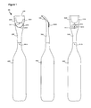
- FIG 1 shows an automatic dental flosser 100, in accordance with the present invention.
- the automatic dental flosser 100 consists of a disposable floss holder 200 attached onto a driving handle 400.
- the disposable floss holder 200 holds a loop of dental floss 210 between two tines 220 and 230.
- a driving mechanism housed inside the driving handle 400 drives a driving shaft 411 to oscillate from side to side.
- the driving shaft 411 then drives a rotatable element 250 to swing back and forth with respect to the disposable floss holder 200.
- the loop of dental floss 210 is drag to slide back and forth between the two tines 220 and 230 for dental flossing, while the disposable floss holder 200 stays stationary with respect to the driving handle 400.
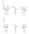
- FIG 2 shows a first embodiment of a disposable floss holder 200, in accordance with the present invention.
- the disposable floss holder 200 is shown in front, side, and back view.
- the disposable floss holder 200 consists of a holder body 201, a rotatable element 250, and a loop of dental floss 210.
- the rotatable element 250 is rotatable with respect to the holder body 201 via a pin-and-hole structure 251.
- One point 255 of the rotatable element 250 is tied to the loop of dental floss 210.
- the rotatable element 250 is affixed with an engagement element 254 that has a notch 253, which can be engaged with the tip of a driving shaft 411 from the driver handle 400, as shown in Figure 1 .
- the driving shaft 411 of the driving handle 400 oscillates from side to side, it drives the rotatable element 250 to swing back and forth with respect to the holder body 201.
- the pin-and-hole structure 251 has two possible configurations.
- the first configuration is to have a hole on the holder body 201 and a pin on the rotatable element 250 to insert into the hole.
- the other configuration is to have a pin on the holder body 201 and a hole on the rotatable element 250 to receive the pin. This way the rotatable element 250 is rotatable around the pin-and-hole structure 251.
- the loop of dental floss 210 is held between the two tines 220 and 230 through holding slots 202, 203, 207, and 206.
- the loop of dental floss 210 is free to slide back and forth around these holding slots 202, 203, 207 and 206.
- the rotatable element 250 swings back and forth around the pin-and-hole structure 251, it drags the loop of dental floss 210 to move back and forth between the two tines 220 and 230.
- the implement of the rotatable element 250 with the engagement element 254 is for two advantages. First, it can enlarge the travel of the dental floss 210 between the two tines 220 and 230, in comparison with the displacement of the driving shaft 411. Second, it provides a simple engagement to transfer the oscillation of the driving shaft 411 to the back-and-forth movement of the dental floss 210 with the floss holder remaining stationary.
- the first end 412 of the driving shaft 411 has a peak-to-peak oscillation of approximately 2 to 3 mm and the dental floss 410 has a back-and-forth travel of about 4 to 8 mm.
- This hole 240 is used to attach and to secure the floss holder 200 onto the driving handle 400.
- FIG 3 shows a second embodiment of a disposable floss holder 300, in accordance with the present invention.
- the disposable floss holder 300 is shown in front, side, and back view.
- This disposable floss holder 300 has similar structure as the disposable floss holder 200 except that the pin-and-hole structure 251 is replaced with a narrow bridge structure 351 and the rotatable element 350 is modified from the rotatable element 250 accordingly.
- the rotatable element 350 is connected and rotatable with respect to the holder body 301 via this narrow bridge structure 351.
- the material chosen for the disposable floss holder 300 shall be durable for bending back and forth over such a narrow bridge structure 351. Materials suitable for this purpose are known to those skilled in the art.
- the rotatable element 350 is coupled with an engagement element 354 that has a notch 353 to engage with the driving shaft 411.
- An opening 356 on the holder body 301 receives the engagement element 354 and allows the engagement element 354 to swing within a range with respect to the narrow bridge structure 351.
- the holder body 301 with the rotatable element 350 can then be made with a single piece of plastic through mold injection process. Such a design simplifies the production process and reduces the production cost. As a result, the floss holder 300 can be better justified as a disposable item.
- FIG 4 shows a first embodiment of a driving handle 400 of the automatic dental flosser 100, in accordance with the present invention.
- the driving handle 400 consists of a handle body 440 and a driving shaft 411.
- the handle body 440 houses a motor 420, a driving mechanism, and a battery or charger that is not shown in the Figure.
- the handle body 440 has an elongate shape and is such shaped to allow the user to grasp comfortably for dental flossing.
- the first end 441 of the handle body 440 is sized to fit into the hole 240 of the disposable floss holder 200.
- the first end 412 of the driving shaft 411 is shaped to fit with the notch 253 of the engagement element 254 of the disposable floss holder 200.
- the driving shaft 411 oscillates from side to side to drive the rotatable element 250 to swing back and forth with respect to the holder body 201 and to drag the loop of dental floss 210 to slide back and forth between the two tines 220 and 230.
- the driving mechanism includes a gear 421, a wheel 430, and a bar 419.
- the motor 420 drives the gear 421, which is coupled to the wheel 430 rotating around a shaft 431.
- the power coupling is through a layer of deformable material 436, e.g. rubber or soft plastic.
- Such a design is for its simplicity and low noise in comparison with typical gear coupling.
- the wheel 430 is concentric and affixed with a smaller wheel 432.
- a pin 437 is mounted on the smaller wheel 432 with an offset from the wheel's center, i.e., the shaft 431.
- the bar 419 has a slot 418 at its first end and extends to the driving shaft 411 at its second end.
- the slot 418 is engaged into the pin 437 of the wheel 432.
- the pin 437 drives the bar 419 to swing back and forth around a pin 413, which is affixed on the handle body 440. Consequently, the bar 419 transfers the continuous rotation of the wheel 430 to a side-to-side oscillation of the driving shaft 411.
- the rotation speed of motor 420, the size of the gear 421, and the size of the wheel 430 are such chosen that the oscillation rate of the driving shaft 411 is about 30 to 50 Hz.
- the length of the driving shaft 411, the length of the bar 419, and the offset of pin 437 are such designed that the tip 412 of the driving shaft 411 has a side-to-side travel of about 2 to 3 mm.
- FIG. 5 shows a second embodiment of a driving handle 500 of the automatic dental flosser 100, in accordance with the present invention.
- the construction of the driving handle 500 is similar to that of the driving handle 400 except the driving mechanism that couples the continuous rotation of the motor 520 to the side-to-side oscillation of the driving shaft 511.
- the driving mechanism includes a first disk 521, a second disk 531, and a bar 519.
- the first disk 521 is affixed on the motor's shaft and is mounted with an off-center pin 522.
- the second disk 531 is affixed on a first end of the bar 519 and is embedded a slot 532.
- the motor 520 rotates the first disk 521 continuously.
- the off-center pin 522 slides inside the slot 532 and pushes the bar 519 to swing back and forth around a pin 513. Consequently, the driving mechanism transfers the continuous rotation of the motor 520 to a side-to-side oscillation of the driving shaft 511.
- the rotation speed of motor 520 is such chosen that the oscillation rate of the driving shaft 511 is about 50 to 100 Hz.
- the length of the driving shaft 511, the length of the bar 519, and the offset of pin 522 are such designed that the tip 512 of the driving shaft 511 has a side-to-side travel of about 2 to 3 mm.
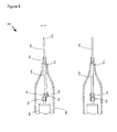
- FIG. 6 shows an automatic dental flosser 600 with the driving shaft 411 at different angle positions.
- the automatic dental flosser 600 is shown in a back view of the floss holder 200.
- the driving shaft 411 is engaged with the notch 253 on the engagement element 254.
- the rotatable element 250 drives in turn the loop of dental floss 210 to slide back and forth between the two tines 220 and 230.
- the size of the rotatable element 250 and the distance from the notch 253 to the rotation center 251 shall be such chosen that the dental floss 210 has a side-to-side travel of about 4 to 8 mm.
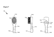
- FIG 7 shows a first embodiment of a toothbrush head 700, in accordance with the present invention.
- the toothbrush head 700 is shown in front, side, and back view.
- the toothbrush head 700 consists of a toothbrush head body 701 and a rotatable bristle holder 750. Toothbrush bristles 730 are implanted on the rotatable bristle holder 750, which is in turn mounted on the first end of the toothbrush head body 701 and is operationally rotatable around a pin-and-hole structure 751.
- the rotatable bristle holder 750 is affixed with an engagement element 754, which has a notch 753 to engage with the driving shaft 411.
- an opening 756 on the toothbrush head body 701 to receive the engagement element 754 and to allow the engagement element 754 to rotate within a range around the pin-and-hole structure 751.
- This hole 740 is used to attach the toothbrush head 700 onto the driving handle 400.
- This hole 741 enables the driving shaft 411 of driving handle 400 to engage with the notch 753 of the engagement element 754 so as to drive the rotatable bristle holder 750.
- the rotatable bristle holder 750 is driven to rotate back and forth around the pin-and-hole structure 751, the bristles 730 wipes back and forth for tooth brushing.
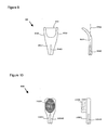
- FIG 8 shows an automatic toothbrush 800 with a toothbrush head 700 at different angle positions of the driving shaft 411.
- the automatic toothbrush 800 is shown in a front view of the toothbrush head 700.
- the driving shaft 411 is engaged with the notch 753 on the engagement element 754. As the driving shaft 411 oscillates from side to side, it drives the rotatable bristle holder 750 to rotate and thus the bristles 730 to wipe back and forth for tooth brushing.
- the size of the rotatable disk 750 and the distance from the notch 753 to the rotation center 751 shall be such chosen that the toothbrush bristles 730 have a back and forth travel distance up to 4 to 8 mm.
- FIG. 9 shows a third embodiment of a disposable floss holder 900, in accordance with the present invention.
- the floss holder 900 has on its first end two tines 920 and 930 securing a piece of dental floss 910 and on its second end a mounting hole 940.
- the two tines 920 and 930 are such shaped and bent to hold the piece of dental floss 910 perpendicular to and about 5 to 20 mm away from an axis 942 of the mounting hole 940.
- the two tines 920 and 930 are further bent and spaced to have the piece of dental floss 910 a length of about 10 to 20 mm.
- the mounting hole 1040 is sized to fit the driving shaft 411 of the driving handle 400.
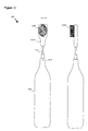
- FIG 11 shows an automatic dental flosser 1100 with a disposable floss holder 900, in accordance with the present invention.
- the automatic dental flosser 1100 consists of a disposable floss holder 900 fastened onto the driving shaft 411 of a driving handle 400. As the driving shaft 411 swings from side to side around the pin 413, the floss holder 900 moves back and forth for dental flossing.
- the length of the disposable floss holder 900 is chosen such that the travel distance of the floss 910 is up to preferably 4 to 6 mm.
- the peak-to-peak oscillation amplitude of the tip 412 of the driving shaft 411 is about 2 to 3 mm and the length of the driving shaft 411 is about 40 mm, the length of the disposable floss holder 900 is approximately 50 mm.
- Figure 10 shows a second embodiment of an attachable toothbrush head 1000, not being part of the present invention.
- the toothbrush head 1000 has bristles 1030 implanted on its first end and a mounting hole 1040 on its second end.
- the mounting hole 1040 is sized to fit the driving shaft 411 of the driving handle 400.
- FIG 12 shows an automatic toothbrush with a toothbrush head 1000.
- the automatic toothbrush 1200 consists of a detachable toothbrush head 1000 fastened onto the driving shaft 411 of a driving handle 400. As the driving shaft 411 swings from side to side around the pin 413, the toothbrush head 1000 wipes back and forth for tooth brushing.
- the length of the detachable toothbrush head 1000 is such chosen that the travel distance of the toothbrush bristles 1030 is preferably 4 to 6 mm.
- the peak-to-peak oscillation amplitude of the tip 412 of the driving shaft 411 is about 2 to 3 mm and the length of the driving shaft 411 is about 40 mm, the length of the detachable toothbrush head 1000 is approximately 50 mm.
- the floss holder 900 adapts the shape of the tines from a popular manual floss holder that is relatively easy to manipulate.
- the floss holder 900 is simple and easy to make, and it is thus better justified to be a disposable item.
- the automatic toothbrush 800 adapts a circular oscillation of the toothbrush bristles 730. Such a circular oscillation has been well accepted in the market.
- the driving handles 400 and 500 implement a side-to-side oscillation of the driving shaft to enable the automatic dental flossers 100 and 1100 and automatic toothbrushes 800 and 1200. Any combination of these automatic dental flossers and toothbrushes can be a useful product.
- floss holder 200 and toothbrush head 700 adapt a similar circular oscillation of a rotatable member. Therefore, other driving mechanism or coupling mechanism that can provide a circular oscillation to a toothbrush head can also be used to drive a floss holder with a rotatable element.
- dental flosser 1100 and toothbrush 800 adapt a hybrid motion, of which the floss holder is driven to swing side to side while the toothbrush bristles are driven to oscillate rotationally.
- driving mechanisms that can provide similar hybrid motion or provide movements including such a hybrid motion.
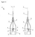
- Figure 13 shows a third embodiment of a driving handle 1300 that is suitable to provide a hybrid motion for dental flossing and tooth brushing, in accordance with the present invention.
- the construction of the driving handle 1300 is similar to that of the driving handle 400 except the driving mechanism that couples the continuous rotation of the motor 1320 to a side-to-side swing oscillation of the driving shaft 1311.
- the driving mechanism includes a disk element 1321, an arm element 1331, and a bar 1319.
- the disk 1321 is affixed on the motor's shaft and is mounted with an off-center pin 1322.
- the arm element 1331 is affixed on a first end of the bar 1319 and is embedded a slot 1332.
- the motor 1320 rotates the disk element 1321 continuously.
- the off-center pin 1322 slides inside the slot 1332 and pushes the bar 1319 to rotate back and forth around a bearing 1313. Consequently, the driving mechanism transfers the continuous rotation of the motor 1320 to a rotational oscillation of the driving shaft 1311 around an axis 1315.
- the driving handle 1300 can drive the floss holder 900 to swing from side to side around an axis 1315 of the driving handle 1300.
- the driving shaft 1311 can drive the toothbrush bristles 730 to oscillate rotationally with respect to the toothbrush head 700. Consequently, the driving handle 1300 provides a hybrid motion for dental flossing and tooth brushing.
Landscapes
- Health & Medical Sciences (AREA)
- Dentistry (AREA)
- Epidemiology (AREA)
- Life Sciences & Earth Sciences (AREA)
- Animal Behavior & Ethology (AREA)
- General Health & Medical Sciences (AREA)
- Public Health (AREA)
- Veterinary Medicine (AREA)
- Brushes (AREA)
- Dental Tools And Instruments Or Auxiliary Dental Instruments (AREA)
- Cosmetics (AREA)
Claims (17)
- Eine Dental-Vorrichtung zum Benutzen von Zahnseide und zum Zähneputzen, wobei die Vorrichtung Dental-Zahnseide (100) und Zahnbürste (800) austauschbar bildet, wobei die Vorrichtung dadurch gekennzeichnet ist, dass sie umfasst:einen Zahnseidehalter (200), der an seinem ersten Ende ein rotierbares Bauteil (250) und zwei Zacken (220, 230) zum Halten einer Schlaufe von Dental-Zahnseide (210) und an seinem zweiten Ende ein Aufsatzbauteil (240) hat, wobei das rotierbare Bauteil (250) mit einem Eingriffsbauteil (254) verbunden ist und in Bezug auf den Zahnseidehalter (200) rotierbar ist und die Schlaufe der Dental-Zahnseide (210) durch das rotierbare Bauteil angetrieben wird, um zwischen den zwei Zacken (220, 230) nach hinten und nach vorn zu gleiten, während das rotierbare Bauteil (250) durch das Eingriffsbauteil (254) angetrieben wird, um rotierend zu oszillieren;einen Zahnbürstenkopf (700), der an seinem ersten Ende eine rotierbare Scheibe (750), in die Zahnbürstenborsten (730) eingesetzt sind, und an seinem zweiten Ende ein Aufsatzbauteil hat, wobei die rotierbare Scheibe (750) mit einem Eingriffsbauteil (754) verbunden ist und in Bezug auf den Zahnbürstenkopf (700) rotierbar ist, und die Zahnbürstenborsten (730) nach hinten und nach vorn wischen, während die rotierbare Scheibe (750) durch das Eingriffsbauteil (754) angetrieben wird, um rotierend zu oszillieren; undein Antriebsgriffstück (400), das einen motorbetriebenen Mechanismus aufnimmt und an seinem ersten Ende ein Antriebsbauteil und ein Haltebauteil hat,wobei der Antriebsmechanismus das Antriebsbauteil antreibt, um rotierend um eine an dem Antriebsgriffstück (400) angebrachte Achse (413) zu oszillieren;
wobei zum Benutzen von Zahnseide der Zahnseidehalter (100) auf dem Haltebauteil des Antriebsgriffstückes (400) aufgesetzt und gesichert ist, das Antriebsbauteil mit dem Eingriffsbauteil (254) des rotierbaren Bauteils eingreift und das rotierbare Bauteil (250) antreibt, um rotierend zu oszillieren, und die Schlaufe der Dental-Zahnseide (210) zwischen den zwei Zacken (220, 230) nach hinten und nach vorn gleitet, um das Benutzen von Zahnseide zu erreichen; und
wobei zum Zähneputzen der Zahnbürstenkopf (700) mit dem Zahnseidehalter (100) austauschbar ist, um es auf dem Haltebauteil des Antriebsgriffstückes (400) aufzusetzen und zu sichern, das Antriebsbauteil in das Eingriffsbauteil (754) der rotierbaren Scheibe eingreift, und die rotierbare Scheibe (750) antreibt, um rotierend zu oszillieren, und die Zahnbürstenborsten (730) zum Zähneputzen nach hinten und nach vorn wischen. - Eine Dental-Hybridvorrichtung zum Benutzen von Zahnseide und zum Zähneputzen, wobei die Vorrichtung Dental-Zahnseide (110) und Zahnbürste (800) austauschbar bildet, wobei die Vorrichtung dadurch gekennzeichnet ist, dass sie umfasst:einen Zahnseidehalter (900), der an seinem ersten Ende zwei Zacken (920, 930), die ein Stück Dental-Zahnseide (910) sichern, und an seinem zweiten Ende eine Befestigungsbauteil hat;einen Zahnbürstenkopf (700), der an seinem ersten Ende eine rotierbare Scheibe (750), in die Zahnbürstenborsten (730) eingesetzt sind, und an seinem zweiten Ende ein Aufsatzbauteil (740) hat, wobei die rotierbare Scheibe (750) so mit einem Eingriffsbauteil (754) verbunden ist, dass die rotierbare Scheibe durch das Eingriffsbauteil angetrieben werden kann, um in Bezug auf den Zahnbürstenkopf (700) rotierend zu oszillieren; undein Antriebsgriffstück (400), das einen motorbetriebenen Mechanismus aufnimmt und an seinem ersten Ende ein Antriebsbauteil und ein Haltebauteil hat,wobei der Antriebsmechanismus das Antriebsbauteil antreibt, um rotierend um eine im Antriebsgriffstück (400) definierte Achse zu oszillieren;
wobei zum Benutzen von Zahnseide der Zahnseidehalter (900) auf das Antriebsbauteil des Antriebsgriffstückes (400) durch das Befestigungsbauteil aufgesetzt und befestigt ist, wobei der Zahnseidehalter angetrieben wird, um mit Bezug auf das Antriebsgriffstück von Seite zu Seite zu oszillieren, und dadurch die Dental-Zahnseide (910) angetrieben wird, sich von Seite zu Seite zu bewegen, um das Benutzen von Zahnseide zu erreichen; und
wobei zum Zähneputzen der Zahnbürstenkopf (700) mit dem Zahnseidehalter (900) austauschbar ist, um auf dem Haltebauteil des Antriebsgriffstückes (400) aufgesetzt und gesichert zu werden, und das Antriebsbauteil des Antriebsgriffstückes in das Eingriffsbauteil der rotierbaren Scheibe eingreift, und wobei die rotierbare Scheibe angetrieben wird, um mit Bezug auf den Zahnbürstenkopf (700) rotierend zu oszillieren, und dadurch wischen die Zahnbürstenborsten (730) rotierend, um das Zähneputzen zu erreichen. - Dental-Vorrichtung nach Anspruch 1, dadurch gekennzeichnet, dass das rotierbare Bauteil (250) des Zahnseidehalters (200) mit dem Zahnseidehalter (200) durch einen Stift-und-Loch-Aufbau (251) verbunden ist.
- Dental-Vorrichtung nach Anspruch 1, dadurch gekennzeichnet, dass das rotierbare Bauteil (350) des Zahnseidehalters (300) mit dem Zahnseidehalter (300) durch eine enge Brückenstruktur (351) verbunden ist.
- Dental-Vorrichtung nach Anspruch 1, dadurch gekennzeichnet, dass das Antriebsbauteil eine Antriebswelle (411) ist, die durch den Antriebsmechanismus antrieben wird, wechselseitig um eine Achse (413) zu schwingen, die an dem Antriebsgriffstück (400) angebracht ist.
- Dental-Vorrichtung nach Anspruch 5, dadurch gekennzeichnet, dass das Eingriffsbauteil (254) des rotierbaren Bauteils (250) des Zahnseidehalters (200) eine Aussparung (253) hat, die geformt ist, eine Spitze (412) der Antriebswelle (411) des Antriebsgriffstückes (400) aufzunehmen.
- Dental-Vorrichtung nach Anspruch 1, dadurch gekennzeichnet, dass das Aufsatzbauteil des Zahnseidehalters (200) aus einem Loch (240) besteht, das dazu dimensioniert ist, das Haltebauteil (441) des Antriebsgriffstückes (400) einzupassen.
- Dental-Vorrichtung nach Anspruch 1, dadurch gekennzeichnet, dass der Zahnseidehalter (200) als ein separates Produkt abgepackt ist.
- Dental-Vorrichtung nach Anspruch 1, dadurch gekennzeichnet, dass die Schlaufe der Dental-Zahnseide (210) gezogen ist, mit einer Auslenkung von ungefähr 4 bis 8 Millimeter nach hinten und nach vorn zu gleiten.
- Dental-Vorrichtung nach Anspruch 1, dadurch gekennzeichnet, dass der Zahnseidehalter (300) aus einem einzelnen Stück Kunststoff hergestellt ist.
- Dental-Vorrichtung nach Anspruch 2, dadurch gekennzeichnet, dass der Zahnseidehalter (900) als ein separates Produkt abgepackt ist.
- Dental-Vorrichtung nach Anspruch 2, dadurch gekennzeichnet, dass das Befestigungsbauteil des Zahnseidehalters (900) aus einem Loch (940) besteht, das dazu dimensioniert ist, das Antriebsbauteil (411) des Antriebsgriffstückes (400) einzupassen.
- Dental-Hybridvorrichtung nach Anspruch 2, dadurch gekennzeichnet, dass das Antriebsbauteil eine Antriebswelle (411) ist, die durch den Antriebsmechanismus angetrieben wird, um mit Bezug auf das Antriebsgriffstück (400) von Seite zu Seite zu schwingen.
- Dental-Vorrichtung nach Anspruch 5, dadurch gekennzeichnet, dass die rotierbare Scheibe (750) des Zahnbürstenkopfes (700) ein Eingriffsbauteil (754) mit einer Aussparung (753) hat, die geformt ist, eine Spitze (412) der Antriebswelle (411) des Antriebsgriffstückes (400) aufzunehmen.
- Dental-Vorrichtung nach Anspruch 1 oder 2, dadurch gekennzeichnet, dass der motorgetriebene Antriebsmechanismus einen Motor (420), ein Zahnrad (421), ein Rad (430), eine Welle (431), einen Stift (437), einen Schlitz (418) und eine Schiene (419) aufweist.
- Dental-Vorrichtung nach Anspruch 1 oder 2, dadurch gekennzeichnet, dass der motorgetriebene Antriebsmechanismus einen Motor (520), eine erste Scheibe (521), eine zweite Scheibe (531), einen außermittigen Stift (522), einen Schlitz (532) und eine Schiene (519) aufweist.
- Dental-Vorrichtung nach Anspruch 1 oder 2, dadurch gekennzeichnet, dass der motorgetriebene Antriebsmechanismus einen Motor (1320), ein Scheibenbauteil (1321), ein Armbauteil (1331), einen außermittigen Stift (1322), einen Schlitz (1332) und eine Schiene (1319) aufweist.
Applications Claiming Priority (5)
| Application Number | Priority Date | Filing Date | Title |
|---|---|---|---|
| US453421 | 1989-12-18 | ||
| US40511902P | 2002-08-22 | 2002-08-22 | |
| US405119P | 2002-08-22 | ||
| US10/453,421 US6886570B2 (en) | 2002-08-22 | 2003-06-02 | Hybrid dental flosser and toothbrush |
| PCT/US2003/026129 WO2004017853A2 (en) | 2002-08-22 | 2003-08-21 | Hybrid dental flosser and toothbrush |
Publications (3)
| Publication Number | Publication Date |
|---|---|
| EP1534171A2 EP1534171A2 (de) | 2005-06-01 |
| EP1534171A4 EP1534171A4 (de) | 2005-11-23 |
| EP1534171B1 true EP1534171B1 (de) | 2008-10-15 |
Family
ID=31891480
Family Applications (1)
| Application Number | Title | Priority Date | Filing Date |
|---|---|---|---|
| EP03793196A Expired - Lifetime EP1534171B1 (de) | 2002-08-22 | 2003-08-21 | Hybrid-dentalgerät zur verwendung von zahnseide und als zahnbürste |
Country Status (6)
| Country | Link |
|---|---|
| US (1) | US6886570B2 (de) |
| EP (1) | EP1534171B1 (de) |
| CN (1) | CN2696571Y (de) |
| AT (1) | ATE410973T1 (de) |
| DE (1) | DE60324163D1 (de) |
| WO (1) | WO2004017853A2 (de) |
Cited By (1)
| Publication number | Priority date | Publication date | Assignee | Title |
|---|---|---|---|---|
| DE102024109969A1 (de) * | 2024-04-10 | 2025-10-16 | DR. SHAFÉ & LAPORTE GmbH | Vorrichtung zur Reinigung von Zahnzwischenräumen mittels Zahnseide |
Families Citing this family (21)
| Publication number | Priority date | Publication date | Assignee | Title |
|---|---|---|---|---|
| US7055531B2 (en) | 2004-07-07 | 2006-06-06 | Rehco, Llc | Electronic oral cleaning device |
| US20040079384A1 (en) * | 2002-10-29 | 2004-04-29 | Ming Lai | Combined dental flosser and toothbrush |
| CA105202S (en) * | 2003-06-30 | 2005-06-02 | Gillette Co | Toothpick magazine |
| US7311108B2 (en) * | 2003-10-09 | 2007-12-25 | The William Getgey Company, Inc. | Motorized flosser and method of use |
| US20050076933A1 (en) * | 2003-10-09 | 2005-04-14 | Getgey William F. | Motorized flosser and associated method of use |
| US8015982B2 (en) * | 2004-10-26 | 2011-09-13 | Wilkinson William T | Toothbrush and flossing system |
| USD535440S1 (en) | 2006-01-20 | 2007-01-16 | William Getgey Company, Inc. | Flossing head of motorized flosser |
| USD532555S1 (en) | 2006-01-27 | 2006-11-21 | William Getgey Company, Inc. | Head and neck of motorized flosser |
| WO2009036587A1 (en) * | 2007-09-18 | 2009-03-26 | Eten Technology Ltd | Dental flosser |
| BRPI0906057B1 (pt) * | 2008-03-06 | 2019-08-06 | Unilever N.V. | Dispositivo vibratório para cuidados com a aparência |
| US20110099748A1 (en) * | 2009-11-05 | 2011-05-05 | Barous Francis A | Dust collection in a rotary floor finishing machine |
| US8491508B2 (en) * | 2010-09-15 | 2013-07-23 | Walton F. Smith | Device and method for stimulating the meibomian glands of the eyelid |
| US8763615B1 (en) * | 2012-09-05 | 2014-07-01 | Rebecca Dominguez | Portable sonic flosser |
| USD819276S1 (en) * | 2016-05-13 | 2018-05-29 | Russell G. Kramer | Flossing tool |
| IT201600102902A1 (it) * | 2016-10-13 | 2018-04-13 | Santagostini Claudio | Dispositivo per l'igiene |
| TWM576447U (zh) | 2018-11-08 | 2019-04-11 | 張鐀方 | 牙線式潔牙裝置 |
| CN210044162U (zh) | 2018-11-12 | 2020-02-11 | 张鐀方 | 牙线式洁牙装置 |
| TWI681733B (zh) * | 2019-04-26 | 2020-01-11 | 潘韞珊 | 防傾倒口腔清潔用具之替換結構 |
| JP2020078558A (ja) * | 2019-12-27 | 2020-05-28 | 宏幸 國司 | 電動糸ようじ。 |
| CN111494047B (zh) * | 2020-04-01 | 2021-07-09 | 优品优家(深圳)科技有限公司 | 一种超声波牙刷 |
| US20240173113A1 (en) * | 2022-11-28 | 2024-05-30 | Erin Small | Multipurpose dental cleaning device |
Family Cites Families (23)
| Publication number | Priority date | Publication date | Assignee | Title |
|---|---|---|---|---|
| US604711A (en) * | 1898-05-31 | Trator of william t | ||
| US3156936A (en) * | 1962-11-21 | 1964-11-17 | Gen Ind Co | Electric toothbrushes |
| US3278963A (en) * | 1962-12-04 | 1966-10-18 | Ronson Corp | Automatic tooth brush |
| US4245658A (en) * | 1979-04-09 | 1981-01-20 | Lecouturier Jacques M | Automatic flossing apparatus |
| US4830032A (en) * | 1986-12-03 | 1989-05-16 | Les Produits Associes Lpa-Broxo S.A. | Power driven flossing device |
| US4880382A (en) * | 1986-12-03 | 1989-11-14 | Les Produits Associes, Lpa Sa | Integrated oral hygiene system |
| US5033150A (en) * | 1990-01-29 | 1991-07-23 | Product Development (S.G.Z.) Ltd. | Motor-driven toothbrush |
| IT1238956B (it) * | 1990-04-18 | 1993-09-17 | Mirko Mazza | Dispositivo per il supporto e l'azionamento di un filo interdentale. |
| US5060681A (en) * | 1990-12-24 | 1991-10-29 | Robert S. Westbrook | Dental flossing device |
| US5279314A (en) * | 1991-12-23 | 1994-01-18 | Advanced Dental Research Corporation | Electric dental flosser |
| CA2072555C (en) * | 1992-06-26 | 2000-12-12 | Yong Gao | Automatic dental flossing device |
| US5253382A (en) * | 1992-08-31 | 1993-10-19 | Janos Beny | Power operated toothbrush |
| US5343883A (en) * | 1992-12-30 | 1994-09-06 | Murayama Ronald K | Sonic dental device and method |
| US5361446A (en) * | 1993-05-06 | 1994-11-08 | Mark Rufo | Toothbrush |
| US5353460A (en) * | 1993-09-24 | 1994-10-11 | Ohio Health Care Products, Inc. | Power driven toothbrush |
| US5400811A (en) * | 1993-09-24 | 1995-03-28 | Meibauer; Robert H. | Power driven tooth flosser |
| US5579786A (en) * | 1995-02-13 | 1996-12-03 | Wolk; Roger S. | Automatic dental flossing device |
| US5625916A (en) * | 1995-05-24 | 1997-05-06 | Mcdougall; Greg | Toothbrush |
| US5975296A (en) * | 1997-10-27 | 1999-11-02 | Gore Enterprise Holdings, Inc. | Dental floss holder |
| US5921254A (en) * | 1998-04-13 | 1999-07-13 | Conair Corporation | Power flossing device |
| US6047711A (en) * | 1999-02-19 | 2000-04-11 | Wagner; Daniel A. | Method and apparatus for converting a power-driven toothbrush into a power-driven flossing device |
| US6178574B1 (en) * | 2000-04-17 | 2001-01-30 | Jeff Stromatt | Bedsheet with pocket |
| US6347425B1 (en) * | 2000-06-28 | 2002-02-19 | Colgate-Palmolive Company | Powered toothbrush having three dimensional rotational head motion |
-
2003
- 2003-06-02 US US10/453,421 patent/US6886570B2/en not_active Expired - Fee Related
- 2003-08-21 CN CNU032077963U patent/CN2696571Y/zh not_active Expired - Fee Related
- 2003-08-21 WO PCT/US2003/026129 patent/WO2004017853A2/en not_active Ceased
- 2003-08-21 DE DE60324163T patent/DE60324163D1/de not_active Expired - Lifetime
- 2003-08-21 EP EP03793196A patent/EP1534171B1/de not_active Expired - Lifetime
- 2003-08-21 AT AT03793196T patent/ATE410973T1/de not_active IP Right Cessation
Cited By (1)
| Publication number | Priority date | Publication date | Assignee | Title |
|---|---|---|---|---|
| DE102024109969A1 (de) * | 2024-04-10 | 2025-10-16 | DR. SHAFÉ & LAPORTE GmbH | Vorrichtung zur Reinigung von Zahnzwischenräumen mittels Zahnseide |
Also Published As
| Publication number | Publication date |
|---|---|
| CN2696571Y (zh) | 2005-05-04 |
| EP1534171A2 (de) | 2005-06-01 |
| WO2004017853A3 (en) | 2004-04-22 |
| DE60324163D1 (de) | 2008-11-27 |
| WO2004017853A2 (en) | 2004-03-04 |
| EP1534171A4 (de) | 2005-11-23 |
| US6886570B2 (en) | 2005-05-03 |
| US20040035439A1 (en) | 2004-02-26 |
| ATE410973T1 (de) | 2008-10-15 |
Similar Documents
| Publication | Publication Date | Title |
|---|---|---|
| EP1534171B1 (de) | Hybrid-dentalgerät zur verwendung von zahnseide und als zahnbürste | |
| KR0127992B1 (ko) | 치솔 및 전동치솔 | |
| US7311108B2 (en) | Motorized flosser and method of use | |
| US5855216A (en) | Dental flossing device | |
| US20030140435A1 (en) | Powered toothbrush | |
| US20040010869A1 (en) | Toothbrush with movable head sections for enhanced oral care | |
| US7434286B2 (en) | Powered toothbrush with improved ergonomics | |
| US20040079384A1 (en) | Combined dental flosser and toothbrush | |
| US20090293212A1 (en) | Electric toothbrush/flosser | |
| US20050076933A1 (en) | Motorized flosser and associated method of use | |
| WO2003063722A1 (en) | Powered toothbrush | |
| CA2374083A1 (en) | Electric toothbrush | |
| US7757331B2 (en) | Electric toothbrush attachment for backside cleaning | |
| CA2522998C (en) | Powered toothbrush with curved neck and flexible shaft | |
| MXPA06003941A (en) | Motorized flosser and associated method of use | |
| US20040226120A1 (en) | Powered toothbrush with curved neck, flexible shaft and tapered head | |
| AU2003207747A1 (en) | Powered toothbrush | |
| WO2006056867A1 (en) | A dental flossing device |
Legal Events
| Date | Code | Title | Description |
|---|---|---|---|
| PUAI | Public reference made under article 153(3) epc to a published international application that has entered the european phase |
Free format text: ORIGINAL CODE: 0009012 |
|
| 17P | Request for examination filed |
Effective date: 20050322 |
|
| AK | Designated contracting states |
Kind code of ref document: A2 Designated state(s): AT BE BG CH CY CZ DE DK EE ES FI FR GB GR HU IE IT LI LU MC NL PT RO SE SI SK TR |
|
| A4 | Supplementary search report drawn up and despatched |
Effective date: 20051011 |
|
| RIC1 | Information provided on ipc code assigned before grant |
Ipc: 7A 61C 17/22 B Ipc: 7A 61C 17/34 B Ipc: 7A 61C 15/04 A |
|
| 17Q | First examination report despatched |
Effective date: 20060213 |
|
| RTI1 | Title (correction) |
Free format text: HYBRID DENTAL DEVICE FOR DENTAL FLOSSING AND TOOTH-BRUSHING |
|
| GRAP | Despatch of communication of intention to grant a patent |
Free format text: ORIGINAL CODE: EPIDOSNIGR1 |
|
| GRAS | Grant fee paid |
Free format text: ORIGINAL CODE: EPIDOSNIGR3 |
|
| GRAA | (expected) grant |
Free format text: ORIGINAL CODE: 0009210 |
|
| AK | Designated contracting states |
Kind code of ref document: B1 Designated state(s): AT BE BG CH CY CZ DE DK EE ES FI FR GB GR HU IE IT LI LU MC NL PT RO SE SI SK TR |
|
| REG | Reference to a national code |
Ref country code: GB Ref legal event code: FG4D Ref country code: CH Ref legal event code: EP |
|
| REG | Reference to a national code |
Ref country code: IE Ref legal event code: FG4D |
|
| REF | Corresponds to: |
Ref document number: 60324163 Country of ref document: DE Date of ref document: 20081127 Kind code of ref document: P |
|
| NLV1 | Nl: lapsed or annulled due to failure to fulfill the requirements of art. 29p and 29m of the patents act | ||
| PG25 | Lapsed in a contracting state [announced via postgrant information from national office to epo] |
Ref country code: ES Free format text: LAPSE BECAUSE OF FAILURE TO SUBMIT A TRANSLATION OF THE DESCRIPTION OR TO PAY THE FEE WITHIN THE PRESCRIBED TIME-LIMIT Effective date: 20090126 Ref country code: BG Free format text: LAPSE BECAUSE OF FAILURE TO SUBMIT A TRANSLATION OF THE DESCRIPTION OR TO PAY THE FEE WITHIN THE PRESCRIBED TIME-LIMIT Effective date: 20090115 Ref country code: AT Free format text: LAPSE BECAUSE OF FAILURE TO SUBMIT A TRANSLATION OF THE DESCRIPTION OR TO PAY THE FEE WITHIN THE PRESCRIBED TIME-LIMIT Effective date: 20081015 |
|
| PG25 | Lapsed in a contracting state [announced via postgrant information from national office to epo] |
Ref country code: NL Free format text: LAPSE BECAUSE OF FAILURE TO SUBMIT A TRANSLATION OF THE DESCRIPTION OR TO PAY THE FEE WITHIN THE PRESCRIBED TIME-LIMIT Effective date: 20081015 Ref country code: FI Free format text: LAPSE BECAUSE OF FAILURE TO SUBMIT A TRANSLATION OF THE DESCRIPTION OR TO PAY THE FEE WITHIN THE PRESCRIBED TIME-LIMIT Effective date: 20081015 Ref country code: PT Free format text: LAPSE BECAUSE OF FAILURE TO SUBMIT A TRANSLATION OF THE DESCRIPTION OR TO PAY THE FEE WITHIN THE PRESCRIBED TIME-LIMIT Effective date: 20090316 Ref country code: SI Free format text: LAPSE BECAUSE OF FAILURE TO SUBMIT A TRANSLATION OF THE DESCRIPTION OR TO PAY THE FEE WITHIN THE PRESCRIBED TIME-LIMIT Effective date: 20081015 |
|
| PG25 | Lapsed in a contracting state [announced via postgrant information from national office to epo] |
Ref country code: BE Free format text: LAPSE BECAUSE OF FAILURE TO SUBMIT A TRANSLATION OF THE DESCRIPTION OR TO PAY THE FEE WITHIN THE PRESCRIBED TIME-LIMIT Effective date: 20081015 Ref country code: EE Free format text: LAPSE BECAUSE OF FAILURE TO SUBMIT A TRANSLATION OF THE DESCRIPTION OR TO PAY THE FEE WITHIN THE PRESCRIBED TIME-LIMIT Effective date: 20081015 Ref country code: RO Free format text: LAPSE BECAUSE OF FAILURE TO SUBMIT A TRANSLATION OF THE DESCRIPTION OR TO PAY THE FEE WITHIN THE PRESCRIBED TIME-LIMIT Effective date: 20081015 Ref country code: DK Free format text: LAPSE BECAUSE OF FAILURE TO SUBMIT A TRANSLATION OF THE DESCRIPTION OR TO PAY THE FEE WITHIN THE PRESCRIBED TIME-LIMIT Effective date: 20081015 |
|
| PLBE | No opposition filed within time limit |
Free format text: ORIGINAL CODE: 0009261 |
|
| STAA | Information on the status of an ep patent application or granted ep patent |
Free format text: STATUS: NO OPPOSITION FILED WITHIN TIME LIMIT |
|
| PG25 | Lapsed in a contracting state [announced via postgrant information from national office to epo] |
Ref country code: CZ Free format text: LAPSE BECAUSE OF FAILURE TO SUBMIT A TRANSLATION OF THE DESCRIPTION OR TO PAY THE FEE WITHIN THE PRESCRIBED TIME-LIMIT Effective date: 20081015 Ref country code: IT Free format text: LAPSE BECAUSE OF FAILURE TO SUBMIT A TRANSLATION OF THE DESCRIPTION OR TO PAY THE FEE WITHIN THE PRESCRIBED TIME-LIMIT Effective date: 20081015 Ref country code: SE Free format text: LAPSE BECAUSE OF FAILURE TO SUBMIT A TRANSLATION OF THE DESCRIPTION OR TO PAY THE FEE WITHIN THE PRESCRIBED TIME-LIMIT Effective date: 20090115 |
|
| 26N | No opposition filed |
Effective date: 20090716 |
|
| PG25 | Lapsed in a contracting state [announced via postgrant information from national office to epo] |
Ref country code: SK Free format text: LAPSE BECAUSE OF FAILURE TO SUBMIT A TRANSLATION OF THE DESCRIPTION OR TO PAY THE FEE WITHIN THE PRESCRIBED TIME-LIMIT Effective date: 20081015 |
|
| PG25 | Lapsed in a contracting state [announced via postgrant information from national office to epo] |
Ref country code: MC Free format text: LAPSE BECAUSE OF NON-PAYMENT OF DUE FEES Effective date: 20090831 |
|
| REG | Reference to a national code |
Ref country code: CH Ref legal event code: PL |
|
| GBPC | Gb: european patent ceased through non-payment of renewal fee |
Effective date: 20090821 |
|
| PG25 | Lapsed in a contracting state [announced via postgrant information from national office to epo] |
Ref country code: LI Free format text: LAPSE BECAUSE OF NON-PAYMENT OF DUE FEES Effective date: 20090831 Ref country code: CH Free format text: LAPSE BECAUSE OF NON-PAYMENT OF DUE FEES Effective date: 20090831 |
|
| REG | Reference to a national code |
Ref country code: FR Ref legal event code: ST Effective date: 20100430 |
|
| REG | Reference to a national code |
Ref country code: IE Ref legal event code: MM4A |
|
| PG25 | Lapsed in a contracting state [announced via postgrant information from national office to epo] |
Ref country code: FR Free format text: LAPSE BECAUSE OF NON-PAYMENT OF DUE FEES Effective date: 20090831 Ref country code: IE Free format text: LAPSE BECAUSE OF NON-PAYMENT OF DUE FEES Effective date: 20090821 |
|
| PG25 | Lapsed in a contracting state [announced via postgrant information from national office to epo] |
Ref country code: GR Free format text: LAPSE BECAUSE OF FAILURE TO SUBMIT A TRANSLATION OF THE DESCRIPTION OR TO PAY THE FEE WITHIN THE PRESCRIBED TIME-LIMIT Effective date: 20090116 |
|
| PG25 | Lapsed in a contracting state [announced via postgrant information from national office to epo] |
Ref country code: GB Free format text: LAPSE BECAUSE OF NON-PAYMENT OF DUE FEES Effective date: 20090821 |
|
| PGFP | Annual fee paid to national office [announced via postgrant information from national office to epo] |
Ref country code: DE Payment date: 20100816 Year of fee payment: 8 |
|
| PG25 | Lapsed in a contracting state [announced via postgrant information from national office to epo] |
Ref country code: LU Free format text: LAPSE BECAUSE OF NON-PAYMENT OF DUE FEES Effective date: 20090821 |
|
| PG25 | Lapsed in a contracting state [announced via postgrant information from national office to epo] |
Ref country code: HU Free format text: LAPSE BECAUSE OF FAILURE TO SUBMIT A TRANSLATION OF THE DESCRIPTION OR TO PAY THE FEE WITHIN THE PRESCRIBED TIME-LIMIT Effective date: 20090416 |
|
| PG25 | Lapsed in a contracting state [announced via postgrant information from national office to epo] |
Ref country code: TR Free format text: LAPSE BECAUSE OF FAILURE TO SUBMIT A TRANSLATION OF THE DESCRIPTION OR TO PAY THE FEE WITHIN THE PRESCRIBED TIME-LIMIT Effective date: 20081015 |
|
| PG25 | Lapsed in a contracting state [announced via postgrant information from national office to epo] |
Ref country code: CY Free format text: LAPSE BECAUSE OF FAILURE TO SUBMIT A TRANSLATION OF THE DESCRIPTION OR TO PAY THE FEE WITHIN THE PRESCRIBED TIME-LIMIT Effective date: 20081015 |
|
| REG | Reference to a national code |
Ref country code: FR Ref legal event code: RERR Free format text: CORRECTION DE BOPI 10/26 - RECOURS EN RESTAURATION OU EN ANNULATION. IL Y A LIEU DE SUPPRIMER : L INSCRIPTION N177941 DU 21/05/2010 CONCERNANT LE BREVET EUROPEEN N1534171 |
|
| REG | Reference to a national code |
Ref country code: DE Ref legal event code: R119 Ref document number: 60324163 Country of ref document: DE Effective date: 20120301 |
|
| PG25 | Lapsed in a contracting state [announced via postgrant information from national office to epo] |
Ref country code: DE Free format text: LAPSE BECAUSE OF NON-PAYMENT OF DUE FEES Effective date: 20120301 |