EP1534155B1 - Vakuumextraktor für die geburtshilfe - Google Patents
Vakuumextraktor für die geburtshilfe Download PDFInfo
- Publication number
- EP1534155B1 EP1534155B1 EP03791514A EP03791514A EP1534155B1 EP 1534155 B1 EP1534155 B1 EP 1534155B1 EP 03791514 A EP03791514 A EP 03791514A EP 03791514 A EP03791514 A EP 03791514A EP 1534155 B1 EP1534155 B1 EP 1534155B1
- Authority
- EP
- European Patent Office
- Prior art keywords
- connector
- vacuum extractor
- suction cup
- piece
- connector piece
- Prior art date
- Legal status (The legal status is an assumption and is not a legal conclusion. Google has not performed a legal analysis and makes no representation as to the accuracy of the status listed.)
- Expired - Lifetime
Links
- 239000000463 material Substances 0.000 claims abstract description 14
- 101100327917 Caenorhabditis elegans chup-1 gene Proteins 0.000 description 15
- 210000003754 fetus Anatomy 0.000 description 7
- 229920000642 polymer Polymers 0.000 description 5
- 238000002347 injection Methods 0.000 description 4
- 239000007924 injection Substances 0.000 description 4
- 238000012384 transportation and delivery Methods 0.000 description 4
- 238000003466 welding Methods 0.000 description 4
- 238000004519 manufacturing process Methods 0.000 description 3
- 239000002184 metal Substances 0.000 description 3
- 239000002861 polymer material Substances 0.000 description 3
- 210000004761 scalp Anatomy 0.000 description 3
- 238000007792 addition Methods 0.000 description 2
- 238000010276 construction Methods 0.000 description 2
- 210000003128 head Anatomy 0.000 description 2
- 230000003014 reinforcing effect Effects 0.000 description 2
- 239000000243 solution Substances 0.000 description 2
- 229910001220 stainless steel Inorganic materials 0.000 description 2
- 239000010935 stainless steel Substances 0.000 description 2
- 210000004291 uterus Anatomy 0.000 description 2
- 229910001369 Brass Inorganic materials 0.000 description 1
- 208000032943 Fetal Distress Diseases 0.000 description 1
- 206010016855 Foetal distress syndrome Diseases 0.000 description 1
- 238000004026 adhesive bonding Methods 0.000 description 1
- 210000001691 amnion Anatomy 0.000 description 1
- QVGXLLKOCUKJST-UHFFFAOYSA-N atomic oxygen Chemical compound [O] QVGXLLKOCUKJST-UHFFFAOYSA-N 0.000 description 1
- 230000015572 biosynthetic process Effects 0.000 description 1
- 239000010951 brass Substances 0.000 description 1
- 230000000295 complement effect Effects 0.000 description 1
- 238000005520 cutting process Methods 0.000 description 1
- -1 e.g. Substances 0.000 description 1
- 239000013013 elastic material Substances 0.000 description 1
- 229920002457 flexible plastic Polymers 0.000 description 1
- 239000003292 glue Substances 0.000 description 1
- 238000012986 modification Methods 0.000 description 1
- 230000004048 modification Effects 0.000 description 1
- 229910052760 oxygen Inorganic materials 0.000 description 1
- 239000001301 oxygen Substances 0.000 description 1
- 210000002826 placenta Anatomy 0.000 description 1
- 239000004417 polycarbonate Substances 0.000 description 1
- 229920000515 polycarbonate Polymers 0.000 description 1
- 230000002035 prolonged effect Effects 0.000 description 1
- 238000005096 rolling process Methods 0.000 description 1
- 238000007789 sealing Methods 0.000 description 1
- 229910052710 silicon Inorganic materials 0.000 description 1
- 239000010703 silicon Substances 0.000 description 1
- 239000007779 soft material Substances 0.000 description 1
- 238000004659 sterilization and disinfection Methods 0.000 description 1
- 238000002604 ultrasonography Methods 0.000 description 1
Images



Classifications
-
- A—HUMAN NECESSITIES
- A61—MEDICAL OR VETERINARY SCIENCE; HYGIENE
- A61B—DIAGNOSIS; SURGERY; IDENTIFICATION
- A61B17/00—Surgical instruments, devices or methods
- A61B17/42—Gynaecological or obstetrical instruments or methods
-
- A—HUMAN NECESSITIES
- A61—MEDICAL OR VETERINARY SCIENCE; HYGIENE
- A61B—DIAGNOSIS; SURGERY; IDENTIFICATION
- A61B17/00—Surgical instruments, devices or methods
- A61B17/42—Gynaecological or obstetrical instruments or methods
- A61B17/44—Obstetrical forceps
- A61B17/442—Obstetrical forceps without pivotal connections, e.g. using vacuum
-
- A—HUMAN NECESSITIES
- A61—MEDICAL OR VETERINARY SCIENCE; HYGIENE
- A61B—DIAGNOSIS; SURGERY; IDENTIFICATION
- A61B17/00—Surgical instruments, devices or methods
- A61B17/30—Surgical pincettes, i.e. surgical tweezers without pivotal connections
- A61B2017/306—Surgical pincettes, i.e. surgical tweezers without pivotal connections holding by means of suction
-
- A—HUMAN NECESSITIES
- A61—MEDICAL OR VETERINARY SCIENCE; HYGIENE
- A61B—DIAGNOSIS; SURGERY; IDENTIFICATION
- A61B17/00—Surgical instruments, devices or methods
- A61B17/30—Surgical pincettes, i.e. surgical tweezers without pivotal connections
- A61B2017/306—Surgical pincettes, i.e. surgical tweezers without pivotal connections holding by means of suction
- A61B2017/308—Surgical pincettes, i.e. surgical tweezers without pivotal connections holding by means of suction with suction cups
Definitions
- the present invention relates to an obstetric suction device, a so called vacuum extractor, comprising a suction cup of a hard material, which suction cup is provided with connection for a tube and a connector piece, whereby the suction device further comprises a towing means of a flexible material as well as a locking means.
- the towing means comprises a handle, a connecting part and a connector.
- Obstetric suction devices are used as aid means at deliveries.
- the indication of use may be fetal distress, fetus problems, which may e.g., show in a weakened pulse of the fetus due to insufficient or closed oxygen addition through the placenta. Further indications of use may e.g., be a prolonged delivery period of the mother and condition of the mother requiring a shortened delivery period. Certain conditions are required for using obstetric suction devices. For example, the child must be fully-developed, 34 weeks old or older, further the amnion must be broken and the external os uteri be fully dilated.
- obstetric suction devices those made of flexible materials, such as e.g., soft polymers, or rubber, alternatively, and those made of hard materials, such e.g., hard polymers or metal, e.g., stainless steel or brass, alternatively.
- a hard obstetric suction device is described being made of metal, preferably stainless steel.
- the suction device comprises a suction cup, which is provided with connector piece in which connector piece a connecting part, e.g., a chain of fixedly secured.
- the suction device further comprises a handle which handle is releasably provided to the connecting part. This suction device is expensive to produce and is thought to be used multiple times.
- US 4,620,544 describes a suction device comprising a suction cup, and a connection means.
- the suction cup is made of metal.
- On the sphere of the suction cup a rotating disc is provided, which rotating disc is provided with a transverse bar, which bar is attached to the disc at both its ends.
- On the transverse bar a ring is attached and in the ring the connecting part, a chain or similar means arranged.
- the chain serves as a connecting part and handle.
- Said rotating disc may create a cutting edge, which can hurt the other.
- the suction cup is high and hard to clean.
- a soft obstetric suction device consisting of silicon of medical quality is described in WO 89/06112 .
- the instrument is made in one piece and consists of a handle and a suction cup.
- the suction cup is available in two sizes having 50 and 60 mm innerdiameter respectively.
- the expected life length of a suction device according to WO 89/06112 is about two years, or 30 sterilisations in an autoclave at 134°C for three minutes, alternatively.
- Said suction cup is an external os uteri instrument which can not be used at all operations.
- US 5,224,947 describes an obstetric vacuum extractor comprising a suction cup and a connecting part.
- the suction cup is made of a soft material and the connecting piece in a semi-hard material.
- the connecting piece which inter alia is made of a tubular element, a tube is arranged to which tube a vacuum pump is connected. This construction is not durable at practical use.
- US 6,074, 399 describes an obstetric vacuum extractor comprising a suction cup, handle and a manually manoeuvred vacuum pump, which parts are delivered as one unit.
- the suction cup is made of a flexible or harder material, alternatively.
- the suction cup or the whole device, alternatively, can be made as a disposable unit.
- the hand pump and the handle can be made for reuse.
- the invention above requires a specially construed pump, in the form of a hand pump, which leads to complicating the manufacturing process.
- the manufacture is further expensive, in particular when the suction device is made as a disposable one, leading to an expensive product when bought.
- the hand pump leads to fact that the product can not be connected and used together with standard tubes.
- US 6,059, 795 describes a suction device which is characterized in that a recess is arranged on the sphere of the suction cup.
- the tube connected to the vacuum pump is lowered into the recess which provides for a smooth sphere of the suction cup and which further provides for application of the suction device in complicated positions.
- GB 2 296 868 discloses an extractor according to the preamble of claim 1.
- an obstetric vacuum extractor totally made of polymeric materials having different properties adapted to what is being required for the suction cup and the towing means, respectively.
- the towing means comprising handle connecting part and connector can be made in one piece.
- the suction cup and the towing means are releasably arranged to each other but simultaneously can be fixed to each other by means of a locking means for maximum security at use.
- the suction cup is preferably injection-moulded as such and the towing means as such. Then the suction cup and the towing means are mounted together to one suction device and are packed and sterilized.
- the suction device is connected to a vacuum pump via a tube connection by means of a tube.
- a disposable obstetric vacuum extractor is made of a hard material comprising a suction cup provided with a tube connection, and a connection means, further comprising a towing means and a locking means.
- the towing means comprises a handle, a connecting part and a connector, which parts can be made in one piece.
- the suction cup is made of a hard material and the towing means in a flexible, non-elastic material.
- the suction cup and the towing means, comprising handle, connecting part and connector are made of disposable polymer materials.
- the suction cup is made of hard polymer, such as a polycarbonate having formstable properties.
- the towing means is e. g., made of a flexible plastic material which does not provide strectching but which is readily bent.
- the connector piece has been made as an integrated part of the suction cup, preferably arranged on the sphere of the suction cup, said connecting part is arranged to be brought to fixation to said connector piece, said connector piece and connecting part being movably fixed to each other.
- the obstetric vacuum extractor of the present invention comprises a suction cup, which in all figures of the drawing is denoted 1.
- the suction device comprises a towing means 6, comprising a handle 7, a connecting part 8 and a connector 9, which parts can be made in one piece. Further the same denotations are used in all figures for the same parts.
- the suction cup 1 has a substantially smooth outer surface, provided with substantially peripherally arranged reinforcing edge 2, which is preferably well rounded.
- the inner side of the suction cup 1 is substantially smooth, as well.
- a releasable bottom plate 14 arranged, having the form of a net in any kind of polymer material.
- the bottom plate 14 distributes the suction force over the whole inner surface of the suction cup 1, to prevent a sticking against the scalp of the fetus.
- the suction cup 1 comes mainly in three different sizes having 40, 50, and 60 mm innerdiameter, respectively. The hard suction cup 1 will not become deformed, which means that one obtains a maximum adherence.
- a connector piece 4 substantially fixedly arranged for fastening the towing means 6.
- a tube connector 5 arranged, which tube connector 5 connects the suction cup 1 with a vacuum pump by means of a substantially releasably arranged tube.
- FIG. 1 a-e the handle is hollow and tubular.
- the connecting part 8 is in the form of a string.
- the connecting part 8 is further bendable sidewise but can not be stretched in a longitudinal direction.
- the connector 9 is a massive or hollow ball, alternatively.
- the connector piece 4 is fixedly arranged and integrated onto the sphere 3 of the suction cup and provided with slot 10.
- the connector piece 4, which in this embidment is present in the form of a casing is further provided with a substantially part spherical inner surface 15.
- the connector 9 in this case in the form of ball is introduced into the connector piece 4 whereby the connecting part 8 runs into the slot 10.
- the thickness of the connecting part 8 is somewhat smaller than the width of the slot 10 to allow for an unimpeded run of the conecting part 8 in the slot 10.
- the tube connector 5 is fixedly arranged on the sphere 3 of the suction cup.
- the outer diameter of the ball is somewhat smaller than the inner diameter of the connector piece 4 leading to an allowance between the inner diameter of the connector piece 4 and the outer diameter of the ball. This leads to in turn that the ball can be readily introduced into the connector piece 4 and that it is movable in all directions.
- the walls inside the connector piece 4, the casing, is preferably made of part spherical surfaces 15, leading to the formation of a ball joint inside the connector piece 4 which in turn provides for advantages when it comes to tensile strength.
- the suction device is further arranged in such a way that the suction cup 1 will release from the scalp of the fetus at traction forces > 20 kg, which is a safety measure mechanism not to hurt the fetus or the mother.
- a locking means 11 is provided in the opening of the connector piece so that the connector 9 should not slide out off the connector piece 4.
- the locking means 11 is a fixable, locking unit in the form of a plug which will become fastened in the opening of the connector piece when the connector 9 has been brought into the connector piece 4.
- the locking means 11, the plug is then secured snapping it or glueing it threto.
- the locking means 11, the plug has a part spherical end surface 16 to make it fit with the sphere of the connector 9, the ball.
- the locking means 11, the plug, or the connector piece 4 alternatively, be arranged to receive part of the connecting part 8 so that the handle 7 can be bent down.
- the locking means 11, the plug is provided with a slot 18.
- the slot 18 is radially directed from the jacket and inwardly and axially running along the locking means 11.
- the connecting part 8 may be partly received by the slot 18 which facilitates the introduction and provides for that the suction cup 1 can be brought further in towards the head of the child to be delivered.
- the connector piece 4 comprises a recess 19 provided in one of its ends, in which recess 19 the connecting part 8 can be partly received.
- the suction cup 1 is brought against the head of the child.
- the suction device is finally mounted which means that the connector 9 as been introduced into the connector piece 4. Then The connector 9 and the connector piece 4 being movably fixed to each other by means of the locking means 11.
- the handle 7 is hollow and tubular, but may of course take other shapes, e.g., being in the form of a ball, disc or cone and being massive.
- the connecting part 8 is string shaped but may also take other shapes, e.g., being in the form of a band or being a chain.
- the connector 9 is a massive or hollow ball, alternatively, but may also take the shape of a cylinder or cone.
- the connector piece 4 is according to the first embodiment fixedly integrated onto the sphere 3 of the suction cup but may also be provided releasably.
- the connector piece 4 is further provided with a substantially part spherical inner surface 15 which inner surface 15 of course may have another shape, as well, inter alia depending on the shape of the connector 9.
- the locking means 11 is provided in the opening of the connector piece and according to the first embodiment the locking means 11 is a fixable, locking unit in the form of plug which is fixed in the connector piece 4, but may of course also be a pin or the similar.
- the locking means 11 is a snappable or glueable unit, according to the embodiment, but may also be welded or rivetted, or the similar.
- the locking means 11, the plug has, further, a part spherical end surface 16 to fit with the sphere of the connector 9, the ball, but the end surface may of course take any other shape inter alia depending on the shape of the connector 9.
- FIG. 2 the handle 7 being hollow and tubular, is provided with a slotted hole 12 transverse to the longitudinal axis of the handle 7.
- the connecting part 8 is a polymer ribbon, preferably a flat, injection moulded ribbon, which is welded by means of an ultrasonic weld.
- the connector piece 4 of the sphere 3 of the suction cup consists of two fittings at a distance from each other, which distance is greater than the width of the connecting part 8, the ribbon. Between the fittings a cross bar is provided, which in this embodiment serves as a connector, somewhat above the surface of the sphere 3 of the suction cup, so that the connecting part 8, the ribbon, can be brought in between the surface of the sphere 3 of the suction cup and the connector 9, the cross bar.
- the length of the connecting part 8, the ribbon may be adjusted by rolling it onto the handle 7.
- the suction cup 1 is moulded as such with the connector piece 4 fixedly provided onto the sphere 3 of the suction cup.
- the connector 9 is integrated and fixedly arranged to the connector piece. Further the handle is moulded as such.
- the parts are then brought together by means of the connecting part 8 and are welded together, preferably using an ultrasonic welding.
- the handle 7 is hollow and tubular but may of course e.g., be formed as a ball, cone or the similar and e.g., be massive.
- the handle 7 is further provided with a slot shaped hole 12, which of course may be shaped in other ways, e.g., circular, or the similar.
- the connecting part 8 is a polymer ribbon, preferably a flat, injection moulded ribbon, but may also take other shapes such as string form or be a chain.
- the connector piece 4 according to the second embodiment consists of two fittings at a distance from each other, whereby the connector piece 4 of course may be shaped in any other way or consist of a casing, or the similar.
- the parts are joined, according to the second embodiment, to each other by means of the connecting means 8 and are welded, preferably using an ultrasonic welding, but may of course be fixed using glue, rivets or the similar.
- the handle 7 (not shown) is hollow and tubular and is provided with a slot shaped hole 12 (not shown).
- the connecting means 8 is a ribbon, e.g., a flat, injection moulded ribbon.
- the connector 9 is a hollow, cylindrical bar around which bar the connector 8 is e.g., wrapped attached thereto by means of an ultrasonic welding or attached thereto in accordance with the second embodiment above.
- the connector 9, the bar is somewhat longer than the width of the connecting means 8, the ribbon, which means that the connector 9, the bar projects somewhat on either side of the connecting means 8, the ribbon.
- the connector piece 4 provided on the sphere 3 of the suction cup comprises two, preferably arcuate fittings, which are connected to the surface of the sphere 3 of the suction cup.
- the fittings In one end the connector piece 4, the fittings, is attached directly to the surface and in the other end there is a small distance between the fittings and the surface of the sphere 3 of the suction cup. Said distance is somewhat smaller than the connector 9, for snapping the connector 9 in.
- the connector 9 may e.g., be finished with a flange in both ends.
- the distance between the two fittings is somewhat greater than the width of the connecting means 8, the ribbon.
- the connector 9 and the connecting means 8 wrapped around it, is introduced into the connector piece 4 so that the projecting ends of the connector 9, the bar, will pass beneath the fittings.
- the connector 9 and the connecting means 8 are then bent upwardly and is snapped to attach but will still become rotatable.
- the handle 7 is hollow and tubular but may also be shaped as a ball, a cone or the similar.
- the handle 7 is further provided with a slot shaped hole 12, which also may be shaped as circle, a cone or the similar.
- the connecting means 8 is a ribbon, e.g., a flat, injection moulded ribbon, but may also take other shapes such as string form or be a chain.
- the connector 9 is a hollow, cylindrical bar, but may also, e.g., be massive and be a ball or the similar.
- the connector piece 4 is provided on the sphere 3 of the suction cup and comprises preferably two arcuate fittings which fittings of course may be designed in other ways and e.g., be any casing or the similar.
- the handle 7 (not shown) is hollow and tubular.
- the connecting means 8 is a ribbon and the conector 9 is a cylindrical, massive or hollow bar.
- the connector piece 4 of this embodiment is a substantially cylindrical casing arranged to the sphere 3 of the suction cup, the cylindrical casing being provided with a slot 10.
- the connector 9 is introduced into the slot 10.
- the locking means 11 may e.g., consist of a glueable plug or the similar.
- the outer diameter of the cylindrical connector 9 is somewhat less than the inner diameter of the connector piece 4, the casing, and the thickness of the connecting means 8, the ribbon is somewhat less than the width of the slot 10.
- the handle 7 is hollow and tubular, but may also be shaped in other ways, e.g., be massive and shaped as a ball or a cone.
- the connecting means 8 is a ribbon, but but may also take other shapes such as string form or be a chain.
- the connector 9 is a cylindrical, massive or hollow bar, but may also be a ball, a cone or the similar.
- the connector piece 4 is, in this fourth embodiment, a substantially cylindrical casing, but may also be shaped in any other suitable way, as e.g., in the form of one or more fittings.
- the locking means 11 may e.g., consist of a glueable plug or the similar, but the parts may also be kept together by means of welding, rivets, or the similar.
- the handle 7 (not shown) is hollow and tubular.
- the connecting means 8 is a ribbon and the connector 9 is a substantially cylindrical hollow bar.
- the connector piece 4 comprises two fittings, provided on the sphere 3 of the suction cup.
- the distance between the fittings is somewhat greater than the width of the connecting means 8, the ribbon.
- the fittings are attached to the surface of the sphere 3 of the suction cup.
- the dsistance between the fittings is somewhat greater than the size of the connector 9, the cylinder.
- the connector is introduced between the fittings.
- the locking means 11 is in this embodiment a pin which is brought into, primarily through one of the fittings and then through the connector 9 and finaly through the second fitting.
- the locking means 11, the pin has substantially the same length as the common length of the fittings and the connector 9.
- the locking means 11, the pin is provided with grooves in order to lock against the connector 9.
- the handle 7 is hollow and tubular, but may also be shaped in other ways, e.g., be massive and shaped as a ball or a cone.
- the connecting means 8 is a ribbon, but but may also be a chain or a string formed unit.
- the connector 9 is a substantially cylindrical hollow bar, but may also be substantially round or conical, massive unit or the similar.
- the connector piece 4 comprises two fittings, provided on the sphere 3 of the suction cup, but the connector piece 4 may also be e.g., one fitting or a casing or the similar.
- the locking means 11 is, in this fifth embodiment, a pin, but may also be a plug, an ultrasound weld or the similar.
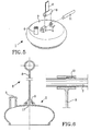
- the handle 7 is a hollow, grooved and resilient cylinder provided with a stop lug 13.
- the connecting means 8 is a ribbon shaped or bar shaped unit. Of the connecting means 8, the ribbon, a loop is made, in which loop the handle 7 is introduced. The stop lug 13 will stop the handle 7 from sliding out of the loop.
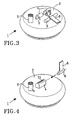
- the suction cup 1 is, according to this embodiment, provided with holes 17 through which the towing means 6 is introduced from beneath and is snapped to attach by means of the connector 9.
- the connector 9 is a massive substantially cylindrical unit, which is fixed to the throughgoing hole 17 of the suction device. Sealing to obtain vacuum is made by means of an O-ring.
- the handle 7 is a hollow, grooved, and resilient cylinder, but may of course be a ball or a cone and e.g., be massive.
- the handle 7 is further provided with a stop lug 13 stopping the handle 7 from sliding out of the loop, but of course, another stopping means may be used in stead of the stop lug 13, e.g., a snapping means or the similar.
- the connecting means 8 is a ribbon shaped or bar shaped unit, which unit of course may be string formed or be a chain.
- the connector 9 is a massive, substantially cylindrical unit, but may even be a conical or ball shaped unit and be hollow or partly hollow.
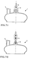
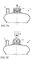
- the connecting means 8 is substantially different types of chains, preferably made of hard polymer material.
- the connector 9 is a rivet.
- the connector 9 is ball moulded into the sphere 3 of the suction cup.
- FIG. 7e and 7f the connector 9 is a chain around own link.
- the connecting means 8 is mainly different types of chains but may also be string formed or ribbon formed units.
- the connector 9 is, in the different FIGs. 7a-f different units which of coursemay be varied and combined between the different embodiments.
Landscapes
- Health & Medical Sciences (AREA)
- Surgery (AREA)
- Life Sciences & Earth Sciences (AREA)
- Gynecology & Obstetrics (AREA)
- Animal Behavior & Ethology (AREA)
- Veterinary Medicine (AREA)
- Reproductive Health (AREA)
- Engineering & Computer Science (AREA)
- Biomedical Technology (AREA)
- Heart & Thoracic Surgery (AREA)
- Medical Informatics (AREA)
- Molecular Biology (AREA)
- Pregnancy & Childbirth (AREA)
- General Health & Medical Sciences (AREA)
- Public Health (AREA)
- Nuclear Medicine, Radiotherapy & Molecular Imaging (AREA)
- External Artificial Organs (AREA)
- Orthopedics, Nursing, And Contraception (AREA)
- Hooks, Suction Cups, And Attachment By Adhesive Means (AREA)
- Transition And Organic Metals Composition Catalysts For Addition Polymerization (AREA)
- Surgical Instruments (AREA)
- Compressors, Vaccum Pumps And Other Relevant Systems (AREA)
- Polarising Elements (AREA)
- Detergent Compositions (AREA)
- Mechanical Treatment Of Semiconductor (AREA)
- Solid-Sorbent Or Filter-Aiding Compositions (AREA)
- Medical Preparation Storing Or Oral Administration Devices (AREA)
Claims (13)
- Ein Vakuumextraktor für die Geburtshilfe umfassend einen Saugnapf (1) aus einem harten Material, der einen Anschluss (5) für ein Rohr und ein Verbindungsstück (4), ein Ziehmittel (6) aus einem flexiblen Material sowie ein Verriegelungsmittel (11) aufweist, wobei das Ziehmittel (6) einen Haltegriff (7), ein Verbindungsteil (8) und einen Verbinder (9) umfasst, wobei das Verbindungsstück (4) ein eingebauter Bestandteil der Kugel des Saugnapfes (1) ist, und der Verbinder (9) so angeordnet ist, dass er im Verbindungsstück (4) festmachbar ist, wobei das Verbindungsstück (4) und der Verbinder (9) beweglich miteinander fixierbar sind, dadurch gekennzeichnet, dass das Verbindungsstück (4) an einem seiner Enden eine Ausnehmung (19) aufweist, sowie eine teilweise kugelförmige Innenoberfläche (15) und einen Schlitz (10), und wobei das Verriegelungsmittel (11) eine fixierbare, verriegelnde Einheit ist, welche im Verbindungsstück (4) so angeordnet ist, dass der Verbinder (9) mit dem Verbindungsstück (4) verriegelt ist.
- Vakuumextraktor für die Geburtshilfe nach Anspruch 1, dadurch gekennzeichnet, dass der Haltegriff (7), das Verbindungsmittel (8) und der Verbinder (9) einstückig ausgebildet sind.
- Vakuumextraktor für die Geburtshilfe nach Anspruch 1, dadurch gekennzeichnet, dass der Haltegriff (7), das Verbindungsmittel (8) und der Verbinder (9) als einzelne Einheiten ausgebildet sind.
- Vakuumextraktor für die Geburtshilfe nach Anspruch 1, dadurch gekennzeichnet, dass das Verbindungsstück (4) eines oder mehrere Teile umfasst.
- Vakuumextraktor für die Geburtshilfe nach Anspruch 1, dadurch gekennzeichnet, dass das Verbindungsmittel (8) schnurförmig ist.
- Vakuumextraktor für die Geburtshilfe nach Anspruch 1, dadurch gekennzeichnet, dass das Verbindungsmittel (8) bandförmig ist.
- Vakuumextraktor für die Geburtshilfe nach Anspruch 1, dadurch gekennzeichnet, dass der Verbinder (9) die Gestalt eines Balles hat.
- Vakuumextraktor für die Geburtshilfe nach Anspruch 1, dadurch gekennzeichnet, dass der Verbinder (9) zylindrisch ist.
- Vakuumextraktor für die Geburtshilfe nach Anspruch 1, dadurch gekennzeichnet, dass die fixierbare, verriegelnde Einheit eine teilweise kugelförmige Endoberfläche (16) aufweist.
- Vakuumextraktor für die Geburtshilfe nach Anspruch 9, dadurch gekennzeichnet, dass die fixierbare, verriegelnde Einheit mit einer radial gerichteten, axial verlaufenden Nut (18) ausgestattet ist, in welcher ein Teil des Verbindungsmittels (8) aufgenommen werden kann.
- Vakuumextraktor für die Geburtshilfe nach Anspruch 1, dadurch gekennzeichnet, dass das Verriegelungsmittel (11) eine einschnappende Einheit ist, welche im Verbindungsstück (4) vorhanden ist.
- Vakuumextraktor für die Geburtshilfe nach Anspruch 1, dadurch gekennzeichnet, dass das Verriegelungsmittel (11) eine klebende Einheit ist, welches im Verbindungsstück (4) vorhanden ist.
- Vakuumextraktor für die Geburtshilfe nach Anspruch 1, dadurch gekennzeichnet, dass das Verriegelungsmittel (11) ein Stift ist, welcher im Verbindungsstück (4) vorhanden ist.
Applications Claiming Priority (3)
| Application Number | Priority Date | Filing Date | Title |
|---|---|---|---|
| SE0202601 | 2002-09-02 | ||
| SE0202601A SE524575C2 (sv) | 2002-09-02 | 2002-09-02 | Obstetrisk suganordning |
| PCT/SE2003/001294 WO2004019794A1 (en) | 2002-09-02 | 2003-08-21 | Obstetric vacuum extractor |
Publications (2)
| Publication Number | Publication Date |
|---|---|
| EP1534155A1 EP1534155A1 (de) | 2005-06-01 |
| EP1534155B1 true EP1534155B1 (de) | 2008-12-10 |
Family
ID=20288877
Family Applications (1)
| Application Number | Title | Priority Date | Filing Date |
|---|---|---|---|
| EP03791514A Expired - Lifetime EP1534155B1 (de) | 2002-09-02 | 2003-08-21 | Vakuumextraktor für die geburtshilfe |
Country Status (11)
| Country | Link |
|---|---|
| EP (1) | EP1534155B1 (de) |
| JP (1) | JP4437955B2 (de) |
| KR (1) | KR100957393B1 (de) |
| CN (1) | CN100453055C (de) |
| AT (1) | ATE416699T1 (de) |
| AU (1) | AU2003253538B2 (de) |
| CA (1) | CA2496903C (de) |
| DE (1) | DE60325226D1 (de) |
| ES (1) | ES2316853T3 (de) |
| SE (1) | SE524575C2 (de) |
| WO (1) | WO2004019794A1 (de) |
Families Citing this family (2)
| Publication number | Priority date | Publication date | Assignee | Title |
|---|---|---|---|---|
| FR2918869B1 (fr) * | 2007-07-16 | 2010-08-20 | Collin Orl | Cupule de systeme de ventouse pour extraction obstetricale et systeme de ventouse pour extraction obstetricale comprenant une telle cupule |
| GB0819157D0 (en) * | 2008-10-18 | 2008-11-26 | Tydeman Graham | Tydeman Tube |
Family Cites Families (5)
| Publication number | Priority date | Publication date | Assignee | Title |
|---|---|---|---|---|
| EP0060249B2 (de) * | 1980-05-29 | 1987-06-16 | O'NEIL, Alexander George Brian | Vakuum-extraktionsgerät für die geburtshilfe |
| SE427522B (sv) * | 1981-12-28 | 1983-04-18 | Vacuum Extractor Ab | Obstetrisk suganordning till vakuumdrivna forlossningsextraktorer |
| GB2296868A (en) * | 1995-01-13 | 1996-07-17 | Galal Elhoussein Elsayed Farag | Obstetrical rotational vacuum cup |
| US5957931A (en) * | 1998-05-11 | 1999-09-28 | Prism Enterprises, Inc. | Obstetrical vacuum extractor cup |
| CN2429126Y (zh) * | 1999-12-25 | 2001-05-09 | 李瑞芹 | 剖宫产胎头牵引器 |
-
2002
- 2002-09-02 SE SE0202601A patent/SE524575C2/sv not_active IP Right Cessation
-
2003
- 2003-08-21 CN CNB038208229A patent/CN100453055C/zh not_active Expired - Fee Related
- 2003-08-21 AU AU2003253538A patent/AU2003253538B2/en not_active Ceased
- 2003-08-21 CA CA2496903A patent/CA2496903C/en not_active Expired - Fee Related
- 2003-08-21 AT AT03791514T patent/ATE416699T1/de not_active IP Right Cessation
- 2003-08-21 DE DE60325226T patent/DE60325226D1/de not_active Expired - Lifetime
- 2003-08-21 WO PCT/SE2003/001294 patent/WO2004019794A1/en not_active Ceased
- 2003-08-21 ES ES03791514T patent/ES2316853T3/es not_active Expired - Lifetime
- 2003-08-21 JP JP2004532492A patent/JP4437955B2/ja not_active Expired - Fee Related
- 2003-08-21 KR KR1020057003608A patent/KR100957393B1/ko not_active Expired - Fee Related
- 2003-08-21 EP EP03791514A patent/EP1534155B1/de not_active Expired - Lifetime
Also Published As
| Publication number | Publication date |
|---|---|
| JP2005537084A (ja) | 2005-12-08 |
| AU2003253538B2 (en) | 2008-09-18 |
| SE524575C2 (sv) | 2004-08-31 |
| KR100957393B1 (ko) | 2010-05-11 |
| CN100453055C (zh) | 2009-01-21 |
| CA2496903C (en) | 2011-08-02 |
| SE0202601D0 (sv) | 2002-09-02 |
| KR20050038647A (ko) | 2005-04-27 |
| WO2004019794A1 (en) | 2004-03-11 |
| ES2316853T3 (es) | 2009-04-16 |
| EP1534155A1 (de) | 2005-06-01 |
| AU2003253538A1 (en) | 2004-03-19 |
| CA2496903A1 (en) | 2004-03-11 |
| DE60325226D1 (de) | 2009-01-22 |
| CN1678246A (zh) | 2005-10-05 |
| SE0202601L (sv) | 2004-03-03 |
| HK1083439A1 (zh) | 2006-07-07 |
| ATE416699T1 (de) | 2008-12-15 |
| JP4437955B2 (ja) | 2010-03-24 |
Similar Documents
| Publication | Publication Date | Title |
|---|---|---|
| US5935136A (en) | Obstetrical vacuum extractor cup with soft molded lip | |
| US6361542B1 (en) | Obstetrical vacuum extractor cup with force measuring capabilities | |
| US5785649A (en) | Surgical retractor stay apparatus | |
| US7314469B2 (en) | Obstetric vacuum extractor | |
| US6175751B1 (en) | Apparatus and method for sensing oxygen levels in a fetus | |
| EP0810892B1 (de) | Stilett zur führung einer enteralen ernährungssonde | |
| US9408633B2 (en) | Obstetrical instrument | |
| EP3632337A1 (de) | Medizinische vorrichtung | |
| WO2009137608A3 (en) | Catheter with spinning ultrasound transceiver board | |
| EP1534155B1 (de) | Vakuumextraktor für die geburtshilfe | |
| US5251617A (en) | Endotracheal tube with concentrically mounted and axially slidable connector | |
| EP1793750B1 (de) | Vakuumextraktor für die geburtshilfe | |
| JP2009508588A (ja) | 挿入/除去ツール付き非バルーン型低背型栄養注入装置 | |
| CN113827169B (zh) | 一种蛇骨单元、蛇骨组件、插入部、内窥镜及连接方法 | |
| JP6813213B2 (ja) | 鉗子 | |
| US5957931A (en) | Obstetrical vacuum extractor cup | |
| JP2012152342A (ja) | 医療用液体および/または栄養剤を患者体内に送り込むために使用する容器 | |
| CN209361596U (zh) | 一种用于固定导管的装置 | |
| CN221600038U (zh) | 一种栓塞弹簧圈 | |
| CN210228191U (zh) | 一种术中经食道超声用咬口器 | |
| CN108542462B (zh) | 一种疝囊高位结扎针 | |
| WO2001003590A1 (en) | Obstetrical vacuum extractor cup |
Legal Events
| Date | Code | Title | Description |
|---|---|---|---|
| PUAI | Public reference made under article 153(3) epc to a published international application that has entered the european phase |
Free format text: ORIGINAL CODE: 0009012 |
|
| 17P | Request for examination filed |
Effective date: 20050314 |
|
| AK | Designated contracting states |
Kind code of ref document: A1 Designated state(s): AT BE BG CH CY CZ DE DK EE ES FI FR GB GR HU IE IT LI LU MC NL PT RO SE SI SK TR |
|
| AX | Request for extension of the european patent |
Extension state: AL LT LV MK |
|
| DAX | Request for extension of the european patent (deleted) | ||
| RAP1 | Party data changed (applicant data changed or rights of an application transferred) |
Owner name: MEDELA HOLDING AG |
|
| 17Q | First examination report despatched |
Effective date: 20071102 |
|
| GRAP | Despatch of communication of intention to grant a patent |
Free format text: ORIGINAL CODE: EPIDOSNIGR1 |
|
| GRAS | Grant fee paid |
Free format text: ORIGINAL CODE: EPIDOSNIGR3 |
|
| GRAS | Grant fee paid |
Free format text: ORIGINAL CODE: EPIDOSNIGR3 |
|
| GRAA | (expected) grant |
Free format text: ORIGINAL CODE: 0009210 |
|
| AK | Designated contracting states |
Kind code of ref document: B1 Designated state(s): AT BE BG CH CY CZ DE DK EE ES FI FR GB GR HU IE IT LI LU MC NL PT RO SE SI SK TR |
|
| REG | Reference to a national code |
Ref country code: GB Ref legal event code: FG4D |
|
| REG | Reference to a national code |
Ref country code: CH Ref legal event code: NV Representative=s name: ISLER & PEDRAZZINI AG Ref country code: CH Ref legal event code: EP |
|
| REG | Reference to a national code |
Ref country code: IE Ref legal event code: FG4D |
|
| REF | Corresponds to: |
Ref document number: 60325226 Country of ref document: DE Date of ref document: 20090122 Kind code of ref document: P |
|
| REG | Reference to a national code |
Ref country code: SE Ref legal event code: TRGR |
|
| REG | Reference to a national code |
Ref country code: ES Ref legal event code: FG2A Ref document number: 2316853 Country of ref document: ES Kind code of ref document: T3 |
|
| PG25 | Lapsed in a contracting state [announced via postgrant information from national office to epo] |
Ref country code: SI Free format text: LAPSE BECAUSE OF FAILURE TO SUBMIT A TRANSLATION OF THE DESCRIPTION OR TO PAY THE FEE WITHIN THE PRESCRIBED TIME-LIMIT Effective date: 20081210 Ref country code: FI Free format text: LAPSE BECAUSE OF FAILURE TO SUBMIT A TRANSLATION OF THE DESCRIPTION OR TO PAY THE FEE WITHIN THE PRESCRIBED TIME-LIMIT Effective date: 20081210 |
|
| PG25 | Lapsed in a contracting state [announced via postgrant information from national office to epo] |
Ref country code: EE Free format text: LAPSE BECAUSE OF FAILURE TO SUBMIT A TRANSLATION OF THE DESCRIPTION OR TO PAY THE FEE WITHIN THE PRESCRIBED TIME-LIMIT Effective date: 20081210 Ref country code: RO Free format text: LAPSE BECAUSE OF FAILURE TO SUBMIT A TRANSLATION OF THE DESCRIPTION OR TO PAY THE FEE WITHIN THE PRESCRIBED TIME-LIMIT Effective date: 20081210 Ref country code: BG Free format text: LAPSE BECAUSE OF FAILURE TO SUBMIT A TRANSLATION OF THE DESCRIPTION OR TO PAY THE FEE WITHIN THE PRESCRIBED TIME-LIMIT Effective date: 20090310 Ref country code: BE Free format text: LAPSE BECAUSE OF FAILURE TO SUBMIT A TRANSLATION OF THE DESCRIPTION OR TO PAY THE FEE WITHIN THE PRESCRIBED TIME-LIMIT Effective date: 20081210 |
|
| PG25 | Lapsed in a contracting state [announced via postgrant information from national office to epo] |
Ref country code: CZ Free format text: LAPSE BECAUSE OF FAILURE TO SUBMIT A TRANSLATION OF THE DESCRIPTION OR TO PAY THE FEE WITHIN THE PRESCRIBED TIME-LIMIT Effective date: 20081210 Ref country code: AT Free format text: LAPSE BECAUSE OF FAILURE TO SUBMIT A TRANSLATION OF THE DESCRIPTION OR TO PAY THE FEE WITHIN THE PRESCRIBED TIME-LIMIT Effective date: 20081210 Ref country code: PT Free format text: LAPSE BECAUSE OF FAILURE TO SUBMIT A TRANSLATION OF THE DESCRIPTION OR TO PAY THE FEE WITHIN THE PRESCRIBED TIME-LIMIT Effective date: 20090511 |
|
| PG25 | Lapsed in a contracting state [announced via postgrant information from national office to epo] |
Ref country code: SK Free format text: LAPSE BECAUSE OF FAILURE TO SUBMIT A TRANSLATION OF THE DESCRIPTION OR TO PAY THE FEE WITHIN THE PRESCRIBED TIME-LIMIT Effective date: 20081210 |
|
| PLBE | No opposition filed within time limit |
Free format text: ORIGINAL CODE: 0009261 |
|
| STAA | Information on the status of an ep patent application or granted ep patent |
Free format text: STATUS: NO OPPOSITION FILED WITHIN TIME LIMIT |
|
| PG25 | Lapsed in a contracting state [announced via postgrant information from national office to epo] |
Ref country code: DK Free format text: LAPSE BECAUSE OF FAILURE TO SUBMIT A TRANSLATION OF THE DESCRIPTION OR TO PAY THE FEE WITHIN THE PRESCRIBED TIME-LIMIT Effective date: 20081210 |
|
| 26N | No opposition filed |
Effective date: 20090911 |
|
| PG25 | Lapsed in a contracting state [announced via postgrant information from national office to epo] |
Ref country code: MC Free format text: LAPSE BECAUSE OF NON-PAYMENT OF DUE FEES Effective date: 20090831 |
|
| REG | Reference to a national code |
Ref country code: IE Ref legal event code: MM4A |
|
| PG25 | Lapsed in a contracting state [announced via postgrant information from national office to epo] |
Ref country code: IE Free format text: LAPSE BECAUSE OF NON-PAYMENT OF DUE FEES Effective date: 20090821 |
|
| PG25 | Lapsed in a contracting state [announced via postgrant information from national office to epo] |
Ref country code: GR Free format text: LAPSE BECAUSE OF FAILURE TO SUBMIT A TRANSLATION OF THE DESCRIPTION OR TO PAY THE FEE WITHIN THE PRESCRIBED TIME-LIMIT Effective date: 20090311 |
|
| PG25 | Lapsed in a contracting state [announced via postgrant information from national office to epo] |
Ref country code: LU Free format text: LAPSE BECAUSE OF NON-PAYMENT OF DUE FEES Effective date: 20090821 |
|
| PG25 | Lapsed in a contracting state [announced via postgrant information from national office to epo] |
Ref country code: HU Free format text: LAPSE BECAUSE OF FAILURE TO SUBMIT A TRANSLATION OF THE DESCRIPTION OR TO PAY THE FEE WITHIN THE PRESCRIBED TIME-LIMIT Effective date: 20090611 |
|
| PG25 | Lapsed in a contracting state [announced via postgrant information from national office to epo] |
Ref country code: TR Free format text: LAPSE BECAUSE OF FAILURE TO SUBMIT A TRANSLATION OF THE DESCRIPTION OR TO PAY THE FEE WITHIN THE PRESCRIBED TIME-LIMIT Effective date: 20081210 |
|
| PG25 | Lapsed in a contracting state [announced via postgrant information from national office to epo] |
Ref country code: CY Free format text: LAPSE BECAUSE OF FAILURE TO SUBMIT A TRANSLATION OF THE DESCRIPTION OR TO PAY THE FEE WITHIN THE PRESCRIBED TIME-LIMIT Effective date: 20081210 |
|
| PGFP | Annual fee paid to national office [announced via postgrant information from national office to epo] |
Ref country code: CH Payment date: 20110818 Year of fee payment: 9 |
|
| PGFP | Annual fee paid to national office [announced via postgrant information from national office to epo] |
Ref country code: DE Payment date: 20110823 Year of fee payment: 9 Ref country code: ES Payment date: 20110812 Year of fee payment: 9 Ref country code: FR Payment date: 20110901 Year of fee payment: 9 Ref country code: GB Payment date: 20110819 Year of fee payment: 9 Ref country code: SE Payment date: 20110824 Year of fee payment: 9 |
|
| PGFP | Annual fee paid to national office [announced via postgrant information from national office to epo] |
Ref country code: IT Payment date: 20110825 Year of fee payment: 9 Ref country code: NL Payment date: 20110825 Year of fee payment: 9 |
|
| REG | Reference to a national code |
Ref country code: NL Ref legal event code: V1 Effective date: 20130301 |
|
| REG | Reference to a national code |
Ref country code: CH Ref legal event code: PL |
|
| REG | Reference to a national code |
Ref country code: SE Ref legal event code: EUG |
|
| GBPC | Gb: european patent ceased through non-payment of renewal fee |
Effective date: 20120821 |
|
| PG25 | Lapsed in a contracting state [announced via postgrant information from national office to epo] |
Ref country code: CH Free format text: LAPSE BECAUSE OF NON-PAYMENT OF DUE FEES Effective date: 20120831 Ref country code: NL Free format text: LAPSE BECAUSE OF NON-PAYMENT OF DUE FEES Effective date: 20130301 Ref country code: LI Free format text: LAPSE BECAUSE OF NON-PAYMENT OF DUE FEES Effective date: 20120831 Ref country code: SE Free format text: LAPSE BECAUSE OF NON-PAYMENT OF DUE FEES Effective date: 20120822 |
|
| REG | Reference to a national code |
Ref country code: FR Ref legal event code: ST Effective date: 20130430 |
|
| PG25 | Lapsed in a contracting state [announced via postgrant information from national office to epo] |
Ref country code: IT Free format text: LAPSE BECAUSE OF NON-PAYMENT OF DUE FEES Effective date: 20120821 |
|
| PG25 | Lapsed in a contracting state [announced via postgrant information from national office to epo] |
Ref country code: GB Free format text: LAPSE BECAUSE OF NON-PAYMENT OF DUE FEES Effective date: 20120821 Ref country code: DE Free format text: LAPSE BECAUSE OF NON-PAYMENT OF DUE FEES Effective date: 20130301 |
|
| PG25 | Lapsed in a contracting state [announced via postgrant information from national office to epo] |
Ref country code: FR Free format text: LAPSE BECAUSE OF NON-PAYMENT OF DUE FEES Effective date: 20120831 |
|
| REG | Reference to a national code |
Ref country code: DE Ref legal event code: R119 Ref document number: 60325226 Country of ref document: DE Effective date: 20130301 |
|
| REG | Reference to a national code |
Ref country code: ES Ref legal event code: FD2A Effective date: 20131018 |
|
| PG25 | Lapsed in a contracting state [announced via postgrant information from national office to epo] |
Ref country code: ES Free format text: LAPSE BECAUSE OF NON-PAYMENT OF DUE FEES Effective date: 20120822 |