EP1533964B1 - Drahtloses lokales Netzwerk mit hoher Datentrate - Google Patents
Drahtloses lokales Netzwerk mit hoher Datentrate Download PDFInfo
- Publication number
- EP1533964B1 EP1533964B1 EP04026613A EP04026613A EP1533964B1 EP 1533964 B1 EP1533964 B1 EP 1533964B1 EP 04026613 A EP04026613 A EP 04026613A EP 04026613 A EP04026613 A EP 04026613A EP 1533964 B1 EP1533964 B1 EP 1533964B1
- Authority
- EP
- European Patent Office
- Prior art keywords
- channel
- channel width
- filter mask
- preamble
- receiver filter
- Prior art date
- Legal status (The legal status is an assumption and is not a legal conclusion. Google has not performed a legal analysis and makes no representation as to the accuracy of the status listed.)
- Expired - Lifetime
Links
- 238000012549 training Methods 0.000 claims description 62
- 238000012545 processing Methods 0.000 claims description 52
- 238000000034 method Methods 0.000 claims description 47
- 239000011159 matrix material Substances 0.000 claims description 14
- 238000004891 communication Methods 0.000 description 64
- 238000010586 diagram Methods 0.000 description 18
- 230000003595 spectral effect Effects 0.000 description 15
- 230000005540 biological transmission Effects 0.000 description 11
- 239000000969 carrier Substances 0.000 description 11
- 238000012360 testing method Methods 0.000 description 10
- 238000010200 validation analysis Methods 0.000 description 10
- 230000001413 cellular effect Effects 0.000 description 8
- 238000006243 chemical reaction Methods 0.000 description 8
- 230000006870 function Effects 0.000 description 8
- 230000010355 oscillation Effects 0.000 description 8
- 238000001914 filtration Methods 0.000 description 7
- 230000007704 transition Effects 0.000 description 6
- 230000008878 coupling Effects 0.000 description 5
- 238000010168 coupling process Methods 0.000 description 5
- 238000005859 coupling reaction Methods 0.000 description 5
- 230000001419 dependent effect Effects 0.000 description 3
- 238000007792 addition Methods 0.000 description 2
- 230000009977 dual effect Effects 0.000 description 2
- 238000005516 engineering process Methods 0.000 description 2
- 238000011084 recovery Methods 0.000 description 2
- 238000001228 spectrum Methods 0.000 description 2
- 238000013461 design Methods 0.000 description 1
- 238000001514 detection method Methods 0.000 description 1
- 230000002349 favourable effect Effects 0.000 description 1
- 238000013507 mapping Methods 0.000 description 1
- 238000010295 mobile communication Methods 0.000 description 1
- 230000001105 regulatory effect Effects 0.000 description 1
- 238000000638 solvent extraction Methods 0.000 description 1
- 230000003068 static effect Effects 0.000 description 1
- 239000013589 supplement Substances 0.000 description 1
Images


Classifications
-
- H—ELECTRICITY
- H04—ELECTRIC COMMUNICATION TECHNIQUE
- H04W—WIRELESS COMMUNICATION NETWORKS
- H04W24/00—Supervisory, monitoring or testing arrangements
- H04W24/02—Arrangements for optimising operational condition
-
- H—ELECTRICITY
- H04—ELECTRIC COMMUNICATION TECHNIQUE
- H04B—TRANSMISSION
- H04B1/00—Details of transmission systems, not covered by a single one of groups H04B3/00 - H04B13/00; Details of transmission systems not characterised by the medium used for transmission
- H04B1/38—Transceivers, i.e. devices in which transmitter and receiver form a structural unit and in which at least one part is used for functions of transmitting and receiving
-
- H—ELECTRICITY
- H04—ELECTRIC COMMUNICATION TECHNIQUE
- H04L—TRANSMISSION OF DIGITAL INFORMATION, e.g. TELEGRAPHIC COMMUNICATION
- H04L27/00—Modulated-carrier systems
- H04L27/26—Systems using multi-frequency codes
- H04L27/2601—Multicarrier modulation systems
- H04L27/2647—Arrangements specific to the receiver only
-
- H—ELECTRICITY
- H04—ELECTRIC COMMUNICATION TECHNIQUE
- H04L—TRANSMISSION OF DIGITAL INFORMATION, e.g. TELEGRAPHIC COMMUNICATION
- H04L5/00—Arrangements affording multiple use of the transmission path
- H04L5/003—Arrangements for allocating sub-channels of the transmission path
- H04L5/0048—Allocation of pilot signals, i.e. of signals known to the receiver
-
- H—ELECTRICITY
- H04—ELECTRIC COMMUNICATION TECHNIQUE
- H04W—WIRELESS COMMUNICATION NETWORKS
- H04W28/00—Network traffic management; Network resource management
- H04W28/16—Central resource management; Negotiation of resources or communication parameters, e.g. negotiating bandwidth or QoS [Quality of Service]
- H04W28/18—Negotiating wireless communication parameters
-
- H—ELECTRICITY
- H04—ELECTRIC COMMUNICATION TECHNIQUE
- H04W—WIRELESS COMMUNICATION NETWORKS
- H04W72/00—Local resource management
- H04W72/50—Allocation or scheduling criteria for wireless resources
- H04W72/54—Allocation or scheduling criteria for wireless resources based on quality criteria
- H04W72/542—Allocation or scheduling criteria for wireless resources based on quality criteria using measured or perceived quality
-
- H—ELECTRICITY
- H04—ELECTRIC COMMUNICATION TECHNIQUE
- H04W—WIRELESS COMMUNICATION NETWORKS
- H04W84/00—Network topologies
- H04W84/02—Hierarchically pre-organised networks, e.g. paging networks, cellular networks, WLAN [Wireless Local Area Network] or WLL [Wireless Local Loop]
- H04W84/10—Small scale networks; Flat hierarchical networks
- H04W84/12—WLAN [Wireless Local Area Networks]
-
- H—ELECTRICITY
- H04—ELECTRIC COMMUNICATION TECHNIQUE
- H04L—TRANSMISSION OF DIGITAL INFORMATION, e.g. TELEGRAPHIC COMMUNICATION
- H04L27/00—Modulated-carrier systems
- H04L27/26—Systems using multi-frequency codes
- H04L27/2601—Multicarrier modulation systems
- H04L27/2602—Signal structure
- H04L27/2605—Symbol extensions, e.g. Zero Tail, Unique Word [UW]
-
- H—ELECTRICITY
- H04—ELECTRIC COMMUNICATION TECHNIQUE
- H04L—TRANSMISSION OF DIGITAL INFORMATION, e.g. TELEGRAPHIC COMMUNICATION
- H04L5/00—Arrangements affording multiple use of the transmission path
- H04L5/0001—Arrangements for dividing the transmission path
- H04L5/0014—Three-dimensional division
- H04L5/0023—Time-frequency-space
-
- H—ELECTRICITY
- H04—ELECTRIC COMMUNICATION TECHNIQUE
- H04W—WIRELESS COMMUNICATION NETWORKS
- H04W24/00—Supervisory, monitoring or testing arrangements
-
- H—ELECTRICITY
- H04—ELECTRIC COMMUNICATION TECHNIQUE
- H04W—WIRELESS COMMUNICATION NETWORKS
- H04W28/00—Network traffic management; Network resource management
- H04W28/02—Traffic management, e.g. flow control or congestion control
- H04W28/06—Optimizing the usage of the radio link, e.g. header compression, information sizing, discarding information
-
- Y—GENERAL TAGGING OF NEW TECHNOLOGICAL DEVELOPMENTS; GENERAL TAGGING OF CROSS-SECTIONAL TECHNOLOGIES SPANNING OVER SEVERAL SECTIONS OF THE IPC; TECHNICAL SUBJECTS COVERED BY FORMER USPC CROSS-REFERENCE ART COLLECTIONS [XRACs] AND DIGESTS
- Y10—TECHNICAL SUBJECTS COVERED BY FORMER USPC
- Y10S—TECHNICAL SUBJECTS COVERED BY FORMER USPC CROSS-REFERENCE ART COLLECTIONS [XRACs] AND DIGESTS
- Y10S370/00—Multiplex communications
- Y10S370/901—Wide area network
-
- Y—GENERAL TAGGING OF NEW TECHNOLOGICAL DEVELOPMENTS; GENERAL TAGGING OF CROSS-SECTIONAL TECHNOLOGIES SPANNING OVER SEVERAL SECTIONS OF THE IPC; TECHNICAL SUBJECTS COVERED BY FORMER USPC CROSS-REFERENCE ART COLLECTIONS [XRACs] AND DIGESTS
- Y10—TECHNICAL SUBJECTS COVERED BY FORMER USPC
- Y10S—TECHNICAL SUBJECTS COVERED BY FORMER USPC CROSS-REFERENCE ART COLLECTIONS [XRACs] AND DIGESTS
- Y10S370/00—Multiplex communications
- Y10S370/908—Local area network
Definitions
- This invention relates generally to wireless communication systems and more particularly to high data throughput communications in such systems.
- Communication systems are known to support wireless and wire lined communications between wireless and/or wire lined communication devices. Such communication systems range from national and/or international cellular telephone systems to the Internet to point-to-point in-home wireless networks. Each type of communication system is constructed, and hence operates, in accordance with one or more communication standards. For instance, wireless communication systems may operate in accordance with one or more standards including, but not limited to, IEEE 802.11, Bluetooth, advanced mobile phone services (AMPS), digital AMPS, global system for mobile communications (GSM), code division multiple access (CDMA), local multi-point distribution systems (LMDS), multi-channel-multi-point distribution systems (MMDS), and/or variations thereof.
- GSM global system for mobile communications
- CDMA code division multiple access
- LMDS local multi-point distribution systems
- MMDS multi-channel-multi-point distribution systems
- a wireless communication device such as a cellular telephone, two-way radio, personal digital assistant (PDA), personal computer (PC), laptop computer, home entertainment equipment, et cetera communicates directly or indirectly with other wireless communication devices.
- the participating wireless communication devices tune their receivers and transmitters to the same channel or channels (e.g., one of the plurality of radio frequency (RF) carriers of the wireless communication system) and communicate over that channel(s).
- RF radio frequency
- each wireless communication device communicates directly with an associated base station (e.g., for cellular services) and/or an associated access point (e.g., for an in-home or in-building wireless network) via an assigned channel.
- the associated base stations and/or associated access points communicate with each other directly, via a system controller, via the public switch telephone network, via the Internet, and/or via some other wide area network.
- each wireless communication device For each wireless communication device to participate in wireless communications, it includes a built-in radio transceiver (i.e., receiver and transmitter) or is coupled to an associated radio transceiver (e.g., a station for in-home and/or in-building wireless communication networks, RF modem, etc.).
- the transmitter includes a data modulation stage, one or more intermediate frequency stages, and a power amplifier.
- the data modulation stage converts raw data into baseband signals in accordance with a particular wireless communication standard.
- the one or more intermediate frequency stages mix the baseband signals with one or more local oscillations to produce RF signals.
- the power amplifier amplifies the RF signals prior to transmission via an antenna.
- the receiver is coupled to the antenna and includes a low noise amplifier, one or more intermediate frequency stages, a filtering stage, and a data recovery stage.
- the low noise amplifier receives inbound RF signals via the antenna and amplifies them.
- the one or more intermediate frequency stages mix the amplified RF signals with one or more local oscillations to convert the amplified RF signal into baseband signals or intermediate frequency (IF) signals.
- the filtering stage filters the baseband signals or the IF signals to attenuate unwanted out of band signals to produce filtered signals.
- the data recovery stage recovers raw data from the filtered signals in accordance with the particular wireless communication standard.
- the assigned channel, or channels, over which the direct or indirect communication occurs is defined by the standard, or standards, supported by the wireless communication devices.
- IEEE 802.11 (a) and (g) provide a channel spectral mask for 20 MHz orthogonal frequency division multiplexing (OFDM) channels.
- the standards also define the manner in which devices communicate over the channel.
- the IEEE 802.11 (a) and (g) standards define a frame structure for communicating via a channel in a WLAN.
- the frame includes a preamble and a variable length data segment.
- the preamble includes a short training sequence, a long training sequence, and a signal field, which provides rate information of the data and length of the data segment.
- Each receiving wireless communication device uses the frame preamble for signal detection, automatic gain control adjustments, diversity determinations, frequency adjustments, timing synchronization, and channel and fine frequency offset estimation.
- Such a frame format allows the wireless communication devices of a WLAN to communicate in a very specific manner. This frame format, however, does not accommodate higher data throughput rates, with backward compatibility to existing WLAN equipment, and various wireless channel configurations.
- IEEE Standard 802.11g June 2003 , there are described changes and additions to the IEEE Standard 802.11 for supporting further higher rate extension for operation in the 2.4 GHz band.
- a method for receiving a frame in a high data throughput wireless local area network begins by, prior to receiving the frame, configuring a receiver filter mask according to a first channel width of a plurality of channel widths to produce a first configured receiver filter mask.
- the processing continues by receiving a first preamble segment of the frame via a channel, wherein the first preamble segment includes a first training sequence, a second training sequence, and a high throughput indication, wherein the first training sequence is within a first set of subcarriers of the channel and the second training sequence is within a second set of subcarriers of the channel, wherein the first set of subcarriers is a subset of the second set of subcarriers in accordance with the first configured receiver filter mask.
- the processing continues by performing a first validation test on the first training sequence. The processing continues by, when the first validation test is successful, performing a second validation test of the second training sequence. The processing continues by, when the second validation test is successful, interpreting the high throughput indication.
- the processing continues by, when the high throughput indication indicates a high data throughput, receiving a second preamble segment of the frame via the channel.
- the processing continues by verifying the second preamble segment to in accordance with a reconfigured receiver filter mask.
- the processing continues by, when the second preamble segment is verified, receiving a data segment of the frame in accordance with the reconfigured receiver filter mask.
- a method for receiving a frame in a high data throughput wireless local area network begins by receiving a preamble of the frame via a channel in accordance with a default receiver filter mask. The processing continues by validating the preamble. The processing continues by, when the preamble is validated, interpreting the preamble to determine a high data throughput channel configuration. The processing continues by reconfiguring the default receiver filter mask in accordance with the high data throughput channel configuration to produce a reconfigured receiver filter mask. The processing continues by receiving a data segment of the frame in accordance with the reconfigured receiver filter mask.
- FIG 1 is a schematic block diagram illustrating a communication system 10 that includes a plurality of base stations and/or access points 12-16, a plurality of wireless communication devices 18-32 and a network hardware component 34.
- the wireless communication devices 18-32 may be laptop host computers 18 and 26, personal digital assistant hosts 20 and 30, personal computer hosts 24 and 32 and/or cellular telephone hosts 22 and 28. The details of the wireless communication devices will be described in greater detail with reference to Figure 2 .
- the base stations or access points 12-16 are operably coupled to the network hardware 34 via local area network connections 36, 38 and 40.
- the network hardware 34 which may be a router, switch, bridge, modem, system controller, et cetera provides a wide area network connection 42 for the communication system 10.
- Each of the base stations or access points 12-16 has an associated antenna or antenna array to communicate with the wireless communication devices in its area via one or more configurable channels within one or more frequency bands.
- the wireless communication devices register with a particular base station or access point 12-14 to receive services from the communication system 10.
- For direct connections i.e., point-to-point communications
- wireless communication devices communicate directly via an allocated channel of the configurable channels.
- each wireless communication device includes a built-in radio and/or is coupled to a radio.
- the radio includes a highly linear amplifier and/or programmable multi-stage amplifier as disclosed herein to enhance performance, reduce costs, reduce size, and/or enhance broadband applications.
- FIG. 2 is a schematic block diagram illustrating a wireless communication device that includes the host device 18-32 and an associated radio 60.
- the radio 60 is a built-in component.
- the radio 60 may be built-in or an externally coupled component.
- the host device 18-32 includes a processing module 50, memory 52, radio interface 54, input interface 58 and output interface 56.
- the processing module 50 and memory 52 execute the corresponding instructions that are typically done by the host device. For example, for a cellular telephone host device, the processing module 50 performs the corresponding communication functions in accordance with a particular cellular telephone standard.
- the radio interface 54 allows data to be received from and sent to the radio 60.
- the radio interface 54 For data received from the radio 60 (e.g., inbound data), the radio interface 54 provides the data to the processing module 50 for further processing and/or routing to the output interface 56.
- the output interface 56 provides connectivity to an output display device such as a display, monitor, speakers, et cetera such that the received data may be displayed.
- the radio interface 54 also provides data from the processing module 50 to the radio 60.
- the processing module 50 may receive the outbound data from an input device such as a keyboard, keypad, microphone, et cetera via the input interface 58 or generate the data itself.
- the processing module 50 may perform a corresponding host function on the data and/or route it to the radio 60 via the radio interface 54.
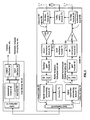
- Radio 60 includes a host interface 62, digital receiver processing module 64, an analog-to-digital converter 66, a filtering/gain module 68, an IF mixing down conversion stage 70, a receiver filter 71, a low noise amplifier 72, a transmitter/receiver switch 73, a local oscillation module 74, memory 75, a digital transmitter processing module 76, a digital-to-analog converter 78, a filtering/gain module 80, an IF mixing up conversion stage 82, a power amplifier 84, a transmitter filter module 85, and an antenna 86.
- the antenna 86 may be a single antenna that is shared by the transmit and receive paths as regulated by the Tx/Rx switch 73, or may include separate antennas for the transmit path and receive path. The antenna implementation will depend on the particular standard to which the wireless communication device is compliant.
- the digital receiver processing module 64 and the digital transmitter processing module 76 in combination with operational instructions stored in memory 75, execute digital receiver baseband functions and digital transmitter baseband functions, respectively.
- the digital receiver functions include, but are not limited to, digital intermediate frequency to baseband conversion, demodulation, constellation demapping, decoding, and/or descrambling.
- the digital transmitter functions include, but are not limited to, scrambling, encoding, constellation mapping, modulation, and/or digital baseband to IF conversion.
- the digital receiver and transmitter processing modules 64 and 76 may be implemented using a shared processing device, individual processing devices, or a plurality of processing devices.
- Such a processing device may be a microprocessor, micro-controller, digital signal processor, microcomputer, central processing unit, field programmable gate array, programmable logic device, state machine, logic circuitry, analog circuitry, digital circuitry, and/or any device that manipulates signals (analog and/or digital) based on operational instructions.
- the memory 75 may be a single memory device or a plurality of memory devices.
- Such a memory device may be a read-only memory, random access memory, volatile memory, non-volatile memory, static memory, dynamic memory, flash memory, and/or any device that stores digital information.
- the processing module 64 and/or 76 implements one or more of its functions via a state machine, analog circuitry, digital circuitry, and/or logic circuitry
- the memory storing the corresponding operational instructions is embedded with the circuitry comprising the state machine, analog circuitry, digital circuitry, and/or logic circuitry.
- the radio 60 receives outbound data 94 from the host device via the host interface 62.
- the host interface 62 routes the outbound data 94 to the digital transmitter processing module 76, which processes the outbound data 94 in accordance with a particular wireless communication standard (e.g., IEEE 802.11 Bluetooth, et cetera) to produce digital transmission formatted data 96.
- the digital transmission formatted data 96 will be a digital base-band signal or a digital low IF signal, where the low IF typically will be in the frequency range of one hundred kilohertz to a few megahertz. Further, the digital transmission formatted data 96 will be based on the channel width of the RF channel on which the data 96 will ultimately be transmitted.
- the channel width may be 10 MHz, 20 MHz, or 40 MHz.
- a 10 MHz wide channel may include 32 subcarrier frequencies
- a 20 MHz wide channel may include 64 subcarrier frequencies
- a 40 MHz wide channel may include 128 subcarrier frequencies, where the number of subcarriers used per channel is at least partially based on the spectral masked configured for the channel. Configuring the spectral mask will be described in greater detail with reference to Figures 3-6 .
- the digital-to-analog converter 78 converts the digital transmission formatted data 96 from the digital domain to the analog domain.
- the filtering/gain module 80 filters and/or adjusts the gain of the analog signal prior to providing it to the IF mixing stage 82.
- the IF mixing stage 82 converts the analog baseband or low IF signal into an RF signal based on a transmitter local oscillation 83 provided by local oscillation module 74.
- the power amplifier 84 amplifies the RF signal to produce outbound RF signal 98, which is filtered by the transmitter filter module 85.
- the antenna 86 transmits the outbound RF signal 98 to a targeted device such as a base station, an access point and/or another wireless communication device. Note that the bandpass regions of the filters 80 and 85 are dependent upon the configured spectral mask for the RF transmission, which may be determined by the digital transmitter processing module 76.
- the radio 60 also receives an inbound RF signal 88 via the antenna 86, which was transmitted by a base station, an access point, or another wireless communication device.
- the antenna 86 provides the inbound RF signal 88 to the receiver filter module 71 via the Tx/Rx switch 73, where the Rx filter 71 bandpass filters the inbound RF signal 88.
- the Rx filter 71 provides the filtered RF signal to low noise amplifier 72, which amplifies the signal 88 to produce an amplified inbound RF signal.
- the low noise amplifier 72 provides the amplified inbound RF signal to the IF mixing module 70, which directly converts the amplified inbound RF signal into an inbound low IF signal or baseband signal based on a receiver local oscillation 81 provided by local oscillation module 74.
- the down conversion module 70 provides the inbound low IF signal or baseband signal to the filtering/gain module 68.
- the filtering/gain module 68 filters and/or gains the inbound low IF signal or the inbound baseband signal to produce a filtered inbound signal. Note that the bandpass regions of the filters 71 and 68 are dependent upon the configured spectral mask for the RF transmission, which may be determined by the receiver processing module 64.
- the analog-to-digital converter 66 converts the filtered inbound signal from the analog domain to the digital domain to produce digital reception formatted data 90.
- the digital receiver processing module 64 decodes, descrambles, demaps, and/or demodulates the digital reception formatted data 90 to recapture inbound data 92 in accordance with the particular wireless communication standard being implemented by radio 60 and the particular channel width of the channel.
- the host interface 62 provides the recaptured inbound data 92 to the host device 18-32 via the radio interface 54.
- the wireless communication device of figure 2 may be implemented using one or more integrated circuits.
- the host device may be implemented on one integrated circuit
- the digital receiver processing module 64, the digital transmitter processing module 76 and memory 75 may be implemented on a second integrated circuit
- the remaining components of the radio 60, less the antenna 86 may be implemented on a third integrated circuit.
- the radio 60 may be implemented on a single integrated circuit.
- the processing module 50 of the host device and the digital receiver and transmitter processing modules 64 and 76 may be a common processing device implemented on a single integrated circuit.
- the memory 52 and memory 75 may be implemented on a single integrated circuit and/or on the same integrated circuit as the common processing modules of processing module 50 and the digital receiver and transmitter processing module 64 and 76.
- FIG 3 is a diagram depicting a plurality of frequency bands (e.g., frequency band 1 through frequency band N), which are defined by a governmental agency for particular wireless applications.
- FCC Federal Communications Commission
- the Federal Communications Commission defines, for the United States, frequency bands for specific uses and for which an FCC license is required (e.g., radio transmissions, television transmissions, etc.) and also defines frequency bands that are unlicensed and, as such, can be used for a variety of applications.
- the FCC has defined several frequency bands in the radio frequency spectrum as being unlicensed.
- Such unlicensed frequency bands include 902-928 MHz, 2.4-2.483 GHz and 5.75-5.85 GHz, which are collectively referred to as the ISM (Industrial Scientific Medical) band.
- the ISM band is used for in-building and system applications (e.g., bar code readers), industrial microwave ovens, wireless patient monitors, and wireless local area networks (WLAN).
- the frequency bands of Figure 3 include, but are not limited to, 2.400 - 2.4835 GHz, 2.471 - 2.497 GHz, 5.15 - 5.25 GHz, 5.25 - 5.35 GHz, 5.47 - 5.725 GHz, 5.725 GHz - 5.825 GHz, 4.9 - 5.3 GHz, and 5.85 - 5.925 GHz.
- Figure 4 is a diagram depicting a particular frequency band that is divided into a plurality of channels.
- the channel width of each channel is selectable. As such, for a given frequency band, the number of channels will vary depending on the selected channel width. For instance, in one embodiment of the present invention, the channel width may be selected in accordance with IEEE 802.11 (a) or (g), where IEEE 802.11 (a) provides wireless LAN operation specifications in the 5.15 to 5.35 GHz band.
- the specified modulation schemes are based on Orthogonal Frequency Division Multiplexing (OFDM) which, for 802.11 (a) divides the 5.15 to 5.35 GHz band into eight 20 MHz wide channels centered at 5.18, 5.20, 5.22, 5.24, 5.26, 5.28, 5.30, and 5.32 GHz.
- OFDM Orthogonal Frequency Division Multiplexing
- the 5.15 to 5.35 GHz band may be divided into eighteen 10 MHz wide channels, with the first channel centered at 5.165 GHz and the remaining seventeen centered at 10 MHz increments therefrom.
- the 5.15 to 5.35 GHz band may be dividing into four 40 MHz wide channels, with the channels centered at 5.21, 5.25, 5.29, and 5.33 GHz.
- the same channel width selectivity may be applied to the 2.4-2.4835 GHz band covered by IEEE 802.11 (g), other frequency bands covered by an IEEE 802.11 standard, and/or any other wireless communication standard.
- the selectivity of the channel width provides for greater data throughput (e.g., at least twice the data rate of IEEE 802.11 (g)), for a diversity of applications, and/or for a single wireless communication device to support multiple wireless standards issued by various standard bodies, including governmental agencies.
- Figure 5 is a diagram of a configurable spectral mask 100 that includes a channel pass region 102, a transition region 104, and a floor region 106.
- the transition region 104 includes a first attenuation region 108, a second attenuation region 110, and a third attenuation region 112.
- Such a spectral mask 100 promotes interoperability, coexistence, and system capacity by limiting interference to adjacent and other channels for a wide variety of applications and/or standards.
- the out of band mask (e.g., the transition region 104 and the floor region 106) places a lower bound on interference levels that can be expected in receivers regardless of their particular implementation. In an effort to minimize the interference energy that appears on top of the desired signal, the out of band regions are made as small as possible.
- the channel pass region 102 which encompasses the desired signal, is of a value as close to the channel bandwidth as feasible.
- the transition region 104 which bounds the adjacent channel interference and is limited by the bandwidth of the baseband processing modules 64 and 76 and the intermediate frequency mixing stage of the up-conversion module 82, is selected to minimize such interference (i.e., post IF inter-modulation distortion (IMD)).
- the floor region 106 which bounds other channel interference, which is outside the range of the filters and IMD limits and is generally limited by the local oscillation 74 phase noise, is selected based on achievable phase noise levels.
- the transition region 104 should have a roll off based on the shoulder height of IMD, which may be assumed to be produced by a 3 rd order compressive non-linearity.
- the distorted signal bandwidth will be no greater than three times the ideal signal bandwidth.
- Figure 6 is a table illustrating a few examples of values for a configurable spectral mask 100. While the table includes channel widths of 10, 20, and 40 MHz, one of average skill in the art will appreciate other channel widths may be used. Further, the transition region may include more or less attenuation regions than the three shown in Figure 5 .
- FIG 7 is a diagram illustrating a radio transmitter section 120 transmitting frames 126A, 126B via a radio frequency (RF) channel 124 to a radio receiver section 122.
- the radio transmitter section 120 is in one wireless communication device and corresponds to the digital transmitter processing module 76, digital-to-analog converter 78, filter/gain module 80, up-conversion module 82, power amplifier 84 and transmit filter module 85 of the wireless communication device of Figure 2 .
- the radio receiver section 122 which is in another wireless communication device, corresponds to the digital receiver processing module 64, analog-to-digital converter 66, filter/gain module 68, down-conversion module 70, the low noise amplifier 72 and receive filter module 71 of the wireless communication device of Figure 2 .
- the channel 124 may be any one of the channels illustrated in Figure 3 and may have any spectral mask configuration as described in co-pending patent application having a serial number of 60/524,528, an attorney docket number of BP3400, entitled CONFIGURABLE SPECTRAL MASK FOR USE IN A HIGH DATA THROUGHPUT WIRELESS COMMUNITATION, with a filing date of 11/24/03.
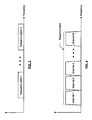
- the format of frames 126A, B includes a 1 st preamble section 128, a 2 nd preamble section 130, and a variable length data segment 132.
- the 1 st preamble training segment 128 includes a 1 st training sequence 134, a 2 nd training sequence 136 and a high throughput channel indication 138.
- the 2 nd preamble segment 130 includes a 3 rd training sequence 140.
- the 1 st training sequence 134 and 2 nd training sequence 136 may correspond to the short and long training sequences of a preamble in accordance with IEEE802.11a or g.
- the high throughput channel indication 138 is set when the transmitting radio desires to use a high throughput channel configuration. If the high throughput channel indication is not set, the 2 nd preamble segment 130 would be ignored and the frame would be formatted similarly to legacy wireless local area networks that operate in accordance with IEEE802.11a, b, g, et cetera.
- the 3 rd training sequence 140 of the 2 nd preamble segment is implemented to fine-tune the radio receiver according to the particular channel configuration.
- the variable length data segment 132 includes a guard interval and associated data fields. The formatting of frame 126 is described in greater detail with reference to Figure 8 .
- the 1 st preamble segment 128 includes the 1 st training sequence 134, the 2 nd training sequence 136 and a signal field.
- the 1 st training sequence 134 includes 10 short training sequences that utilize only a portion of the sub-carriers of the particular channel.
- the channel configuration may be a 20MHz channel bandwidth with 64 sub-carriers.
- the 1 st training sequence 134 may only use 12 of the 52 data sub-carriers to convey the corresponding short training sequence.
- the 2 nd training sequence 136 includes 2 long training sequences that may utilize 52 of the 52 data sub-carriers of a 20MHz, 64 subcarrier channel.
- the signal field includes a guard interval (GI) and includes 24 bits of information.
- GI guard interval
- the 1 st 4 bits correspond to the rate of the data transmission, the next bit indicates the high through-put channel indication 138, the next 12 bits correspond to the length of the variable length data segment 132, bit 17 corresponds to the parity of the data and the remaining 6 bits correspond to a signal tail.
- the receiving radio will configure itself based on a default or 1 st channel configuration which may be the 20MHz bandwidth channel utilizing 64 sub-carriers as currently defined in IEEE802.11a and/or g. If, however, the high throughput channel indication 138 is set, and the receiver is capable of alternative channel configurations, it will begin interpreting the 2 nd preamble.
- the 2 nd preamble segment 130 includes a channel format identification field and a 3 rd training sequence 140.
- the channel identification field may include an additional 4-bits for rate information, 5-bits of channel configuration information, 12-bits to indicate a training matrix, and the remaining 3-bits may be reserved.
- the 24-bits of the channel format identification field may be configured in a variety of ways to convey information to the receiving radio as to the bit rate of the high throughput data, the channel configuration on which the high throughput data will be conveyed, a diversity antenna arrangement, and a training matrix to produce dual RF transmissions over a single channel.
- the receiving radio reconfigures itself based on the channel configuration and the data rate. Having reconfigured itself, the radio receives the 3 rd training sequence 140 that utilizes a majority of the sub-carriers in accordance with the new channel configuration.
- the channel configurations will be described in greater detail with reference to Figure 9 .
- the rate bits in the 1 st preamble and 2 nd preamble may be used in combination to provide 8-bits of rate information and/or may be used separately to provide, in the case of dual communications over a single path, to indicate the rates of the separate communications.
- variable length data segment 132 includes a plurality of data segments and associated guard intervals (GI).
- GI guard intervals
- Figure 9 is a table illustrating the various channel configurations, which may be utilized to convey the high data throughput communications.
- the channel configuration table includes a column for the bits to index the particular channel configuration and configuration information, which includes channel bandwidth, number of sub-carriers per channel, rate interpretation (i.e., are the rate bits in each of the preamble sections to be combined or used separately) and space time coding (i.e., the number of channel paths that the particular RF channel is supporting).
- rate interpretation i.e., are the rate bits in each of the preamble sections to be combined or used separately
- space time coding i.e., the number of channel paths that the particular RF channel is supporting.
- there are 3 channel bandwidth options 1OMHz, 20MHz, and 40MHz.
- the default operation of the wireless communication system in accordance with the present invention would operate as defined in IEEE802.11a or g.
- the channel configuration for 802.11A and/or G includes a 20MHz channel bandwidth utilizing 64 sub-carriers where only 1 path is supported by the RF channel.
- the default channel configuration is not in the channel configuration information in the 2 nd preamble section.
- the rate on both channels is the same corresponding to a rate interpretation of 0, which allows the eight bits (4 from the first preamble segment and 4 from the second preamble segment to be combined into one 8 bit code). If the rates for the 2 paths in space time coding are different, then the rate interpretation is 1. In this instance, the 4 bits of rate information in the 1 st preamble segment is used to indicate the rate of one of the channel paths and the 4 bits of rate information in the 2 nd preamble segment are used to indicate the rate of the other channel path.
- the 40 MHz channel bandwidth may include 128 sub-carriers and support 1 or 2 paths per channel.
- the 10MHz channel bandwidth has 64 sub-carriers and may support 1 or 2 channel paths.
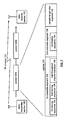
- Figure 10 is a logic diagram of a method for receiving a frame in a high data throughput wireless local area network.
- the processing begins at step 150, where, prior to receiving the frame, a radio receiver configures a receiver filter mask according to a first channel width of a plurality of channel widths to produce a first configured receiver filter mask.
- the first channel width may correspond to a 20 MHz channel bandwidth as defined in IEEE 802.11 (a) and/or (g).
- the receiver will configure its receiver filter mask in accordance with the spectral mask with which the frame was transmitted.
- the process then proceeds to step 152 where the radio receiver receives a first preamble segment of the frame via a channel.
- the first preamble segment includes a first training sequence, a second training sequence, and a high throughput indication.
- the first training sequence is within a first set of subcarriers of the channel and the second training sequence is within a second set of subcarriers of the channel, wherein the first set of subcarriers is a subset of the second set of subcarriers in accordance with the first configured receiver filter mask.
- the process then proceeds to step 154 where the radio receiver performs a first validation test on the first training sequence.
- the process then proceeds to step 156 where the radio receiver determines whether the first validation test was successful. If not, the process proceeds to step 158 where the radio receiver deems the frame to be invalid and it waits for another frame to be received. When a new frame is received, the process continues at step 152.
- step 160 the radio receiver performs a second validation test of the second training sequence.
- step 162 the radio receiver determines whether the second validation test was successful. If not, the process proceeds to step 158 where the radio receiver deems the frame to be invalid and it waits for another frame to be received. When a new frame is received, the process continues at step 152.
- the radio receiver interprets the high throughput indication. In one embodiment, this may be done by interpreting a channel format field of the second preamble to determine a high data throughput channel configuration.
- the high data throughput channel configuration may indicate a second channel width of the plurality of channel widths, wherein the second channel width has 2 M subcarriers received via a single antenna and is greater in width than the first channel width; a third channel width of the plurality of channel widths, wherein the third channel has 2 K subcarriers received via the single antenna and is less in width than the first channel width; the first channel width having 2 N subcarriers received via multiple antennas; the second channel width having 2 M subcarriers received via the multiple antennas; and the third channel width having 2 K subcarriers received via the multiple antennas.
- step 166 the radio receiver determines whether the high throughput indication indicates a high data throughput. If not, the process proceeds to step 168 wherein the radio receiver receives a data segment of the frame via the channel in accordance with the first configured receiver filter mask. After receiving the remainder of the frame, the process reverts to step 150 for a subsequent frame.
- the process proceeds to step 170 wherein the radio receiver receives a second preamble segment of the frame via the channel.
- the process then proceeds to step 172 where the radio receiver interprets a configuration portion of the second preamble segment to determine a new mask configuration and then reconfigures the receiver filter mask accordingly.
- the radio receiver verifies a third training sequence of the second preamble segment to in accordance with a reconfigured receiver filter mask.
- the second preamble segment may be verified by: reconfiguring the receiver filter mask according to the second channel width to produce the reconfigured receiver filter mask, wherein the channel has a second channel width and includes 2 M subcarriers transmitted via the single antenna; and validating a second channel width single antenna training sequence of the second preamble segment in accordance with the reconfigured receiver filter mask.
- the second preamble segment may be verified by: reconfiguring the receiver filter mask according to the third channel width to produce the reconfigured receiver filter mask, wherein the channel has a third channel width and includes 2 K subcarriers transmitted via the single antenna; and validating a third channel width single antenna training sequence of the second preamble segment in accordance with the reconfigured receiver filter mask.
- the second preamble segment may be verified by: identifying a training matrix from the second preamble segment in accordance with the first configured receiver filter mask, wherein the channel has the first channel width and includes 2 N subcarriers transmitted via the multiple antennas; and validating a first channel width multiple antenna training sequence of the second preamble segment in accordance with the first configured receiver filter mask and the training matrix, wherein, when the first channel width multiple antenna training sequence is validated, the receiving the data segment includes receiving parallel data segments of the frame via the channel in accordance with the first receiver filter mask and the training matrix.
- the second preamble segment may be verified by: reconfiguring the receiver filter mask according to the second channel width to produce the reconfigured receiver filter mask, wherein the channel has second channel width and includes 2 M subcarriers transmitted via the multiple antennas; identifying a training matrix from the second preamble segment in accordance with the reconfigured receiver filter mask; and validating a second channel width multiple antenna training sequence of the second preamble segment in accordance with the initial configured receiver filter mask and the training matrix, wherein, when the second channel width multiple antenna training sequence is validated, the receiving the data segment includes receiving parallel data segments of the frame in accordance with the reconfigured receiver filter mask via the channel in accordance with the reconfigured receiver filter mask and the training matrix.
- the second preamble segment is verified by: reconfiguring the receiver filter mask according to the third channel width to produce a reconfigured receiver filter mask, wherein the channel has the third channel width and includes 2 K subcarriers transmitted via the multiple antennas; identifying a training matrix from the second preamble segment in accordance with the reconfigured receiver filter mask; and validating a third channel width multiple antenna training sequence of the second preamble segment in accordance with the reconfigured receiver filter mask and the training matrix, wherein, when the third channel width multiple antenna training sequence is validated, the receiving the data segment includes receiving parallel data segments of the frame via the channel in accordance with the reconfigured receiver filter mask and the training matrix.
- step 176 the radio receiver determines whether the second preamble segment has been verified. If not, the process reverts to step 150. If the second preamble was verified, the process proceeds to step 178 wherein the radio receiver receives a data segment of the frame in accordance with the reconfigured receiver filter mask. Once the frame has been fully received, the process repeats at step 150 for a subsequent frame.
- FIG 11 is a logic diagram of a method for receiving a frame in a high data throughput wireless local area network.
- the process begins at step 180 where a radio receiver receives a preamble of the frame via a channel in accordance with a default receiver filter mask.
- the process then proceeds to step 182 where the radio receiver validates the preamble.
- the process then proceeds to step 184 where the radio receiver determines whether the preamble is validated, which may be done in two parts: the first part using the default receiver filter mask and the second part using a reconfigured receiver filter mask. If it is not, the process proceeds to step 186 where the radio receiver determines that the current frame is invalid and waits for another frame to be received.
- step 188 the radio receiver interprets the preamble to determine a high data throughput channel configuration.
- step 190 the radio receiver reconfigures the default receiver filter mask in accordance with the high data throughput channel configuration to produce a reconfigured receiver filter mask.
- step 192 the radio receiver receives a data segment of the frame in accordance with the reconfigured receiver filter mask.
- the term “substantially” or “approximately”, as may be used herein, provides an industry-accepted tolerance to its corresponding term. Such an industry-accepted tolerance ranges from less than one percent to twenty percent and corresponds to, but is not limited to, component values, integrated circuit process variations, temperature variations, rise and fall times, and/or thermal noise.
- the term “operably coupled”, as may be used herein, includes direct coupling and indirect coupling via another component, element, circuit, or module where, for indirect coupling, the intervening component, element, circuit, or module does not modify the information of a signal but may adjust its current level, voltage level, and/or power level.
- inferred coupling includes direct and indirect coupling between two elements in the same manner as “operably coupled”.
- the term "compares favorably”, as may be used herein indicates that a comparison between two or more elements, items, signals, etc., provides a desired relationship. For example, when the desired relationship is that signal 1 has a greater magnitude than signal 2, a favorable comparison may be achieved when the magnitude of signal 1 is greater than that of signal 2 or when the magnitude of signal 2 is less than that of signal 1.
Landscapes
- Engineering & Computer Science (AREA)
- Signal Processing (AREA)
- Computer Networks & Wireless Communication (AREA)
- Quality & Reliability (AREA)
- Mobile Radio Communication Systems (AREA)
- Circuits Of Receivers In General (AREA)
Claims (10)
- Verfahren zum Empfangen eines Frames in einem drahtlosen lokalen Netzwerk mit hohem Datendurchsatz, wobei das Verfahren umfasst:Empfangen (180) einer Präambel des Frames über einen Kanal gemäß einer Standard-Empfängerfiltermaske;Validieren (182) der Präambel;wenn die Präambel validiert ist, Interpretieren (188) der Präambel, um eine Kanalkonfiguration mit hohem Datendurchsatz zu ermitteln;Rekonfigurieren (190) der Standard-Empfängerfiltermaske gemäß der Kanalkonfiguration mit hohem Datendurchsatz, um eine rekonfigurierte Empfängerfiltermaske zu erzeugen; undEmpfangen (192) eines Datensegments des Frames gemäß der rekonfigurierten Empfängerfiltermaske.
- Verfahren nach Anspruch 1, wobei die Kanalkonfiguration mit hohem Datendurchsatz wenigstens eines aufweist von:einer ersten Kanalbreite einer Vielzahl von Kanalbreiten, wobei die erste Kanalbreite 2N Unterträger hat, die über eine einzige Antenne empfangen werden;einer zweiten Kanalbreite der Vielzahl von Kanalbreiten, wobei die zweite Kanalbreite 2M Unterträger hat, die über die einzige Antenne empfangen werden und eine größere Breite hat als die erste Kanalbreite;einer dritten Kanalbreite der Vielzahl von Kanalbreiten, wobei die dritte Kanalbreite 2K Unterträger hat, die über die einzige Antenne empfangen werden und eine kleinere Breite hat als die erste Kanalbreite;wobei die erste Kanalbreite 2N Unterträger hat, die über mehrere Antennen empfangen werden;wobei die zweite Kanalbreite 2M Unterträger hat, die über die mehreren Antennen empfangen werden; undwobei die dritte Kanalbreite 2K Unterträger hat, die über die mehreren Antennen empfangen werden.
- Verfahren nach Anspruch 2, das des Weiteren umfasst:wenn die Kanalkonfiguration mit hohem Datendurchsatz die zweite Kanalbreite ist, die 2M Unterträger hat, die über die einzige Antenne übertragen werden, umfasst das Interpretieren der Präambel:Rekonfigurieren der Empfängerfiltermaske gemäß der zweiten Kanalbreite, um die rekonfigurierte Empfängerfiltermaske zu erzeugen; undValidieren einer Trainingssequenz der zweiten Kanalbreite der einzigen Antenne des zweiten Präambel-Segments gemäß der rekonfigurierten Empfängerfiltermaske.
- Verfahren nach Anspruch 2, das des Weiteren umfasst:wenn die Kanalkonfiguration mit hohem Datendurchsatz die dritte Kanalbreite ist, die 2K Unterträger hat, die über die einzige Antenne übertragen werden, umfasst das Interpretieren der Präambel:Rekonfigurieren der Empfängerfiltermaske gemäß der dritten Kanalbreite, um die rekonfigurierte Empfängerfiltermaske zu erzeugen; undValidieren einer Trainingssequenz der dritten Kanalbreite der einzigen Antenne des zweiten Präambel-Segments gemäß der rekonfigurierten Empfängerfiltermaske.
- Verfahren nach Anspruch 2, das des Weiteren umfasst:wenn die Kanalkonfiguration mit hohem Datendurchsatz die erste Kanalbreite ist, die 2N Unterträger hat, die über die mehreren Antennen übertragen werden, umfasst das Interpretieren der Präambel:Rekonfigurieren der Empfängerfiltermaske gemäß der ersten Kanalbreite, um die rekonfigurierte Empfängerfiltermaske zu erzeugen;Identifizieren einer Trainingsmatrix von der Präambel gemäß der ersten konfigurierten Empfängerfiltermaske; undValidieren einer Trainingssequenz der ersten Kanalbreite der mehreren Antennen des zweiten Präambel-Segments gemäß der ersten konfigurierten Empfängerfiltermaske und der Trainingsmatrix, wobei, wenn die Trainingssequenz der ersten Kanalbreite der mehreren Antennen validiert ist, das Empfangen des Datensegments das Empfangen paralleler Datensegmente des Frames über den Kanal gemäß der ersten Empfängerfiltermaske und der Trainingsmatrix umfasst.
- Verfahren nach Anspruch 1, wobei das Validieren der Präambel umfasst:Verifizieren einer Trainingssequenz gemäß der Standard-Empfängerfiltermaske.
- Verfahren nach Anspruch 6, das des Weiteren umfasst:Verifizieren einer zweiten Trainingssequenz gemäß der rekonfigurierten Empfängerfiltermaske vor dem Empfangen des Datensegments.
- Funkempfänger mit:einem Hochfrequenz-Frontend, das betriebsbereit gekoppelt ist, um eingehende Hochfrequenzsignale in eingehende Basisbandsignale umzuwandeln;einem Verarbeitungsmodul (64); undeinem Speicher (75), der betriebsbereit an das Verarbeitungsmodul (64) gekoppelt ist, wobei der Speicher (75) Betriebsbefehle speichert, die veranlassen, dass das Verarbeitungsmodul (64):eine Präambel des Frames über einen Kanal gemäß einer Standard-Empfängerfiltermaske identifiziert;die Präambel validiert;wenn die Präambel validiert ist, die Präambel interpretiert, um eine Kanalkonfiguration mit hohem Datendurchsatz zu ermitteln;die Standard-Empfängerfiltermaske gemäß der Kanalkonfiguration mit hohem Datendurchsatz rekonfiguriert, um eine rekonfigurierte Empfängerfiltermaske zu erzeugen; undein Datensegment des Frames gemäß der rekonfigurierten Empfängerfiltermaske verarbeitet.
- Funkempfänger nach Anspruch 8, wobei die Kanalkonfiguration mit hohem Datendurchsatz wenigstens eines aufweist von:einer ersten Kanalbreite einer Vielzahl von Kanalbreiten, wobei die erste Kanalbreite 2N Unterträger hat, die über eine einzige Antenne empfangen werden;einer zweiten Kanalbreite der Vielzahl von Kanalbreiten, wobei die zweite Kanalbreite 2M Unterträger hat, die über die einzige Antenne empfangen werden und eine größere Breite hat als die erste Kanalbreite;einer dritten Kanalbreite der Vielzahl von Kanalbreiten, wobei die dritte Kanalbreite 2K Unterträger hat, die über die einzige Antenne empfangen werden und eine kleinere Breite hat als die erste Kanalbreite;wobei die erste Kanalbreite 2N Unterträger hat, die über mehrere Antennen empfangen werden;wobei die zweite Kanalbreite 2M Unterträger hat, die über die mehreren Antennen empfangen werden; undwobei die dritte Kanalbreite 2K Unterträger hat, die über die mehreren Antennen empfangen werden.
- Funkempfänger nach Anspruch 9, wobei der Speicher (76) des Weiteren Betriebsbefehle speichert, die veranlassen, dass das Verarbeitungsmodul (64):wenn die Kanalkonfiguration mit hohem Datendurchsatz die zweite Kanalbreite ist, die 2M Unterträger hat, die über die einzige Antenne übertragen werden, die Präambel interpretiert durch:Rekonfigurieren der Empfängerfiltermaske gemäß der zweiten Kanalbreite, um die rekonfigurierte Empfängerfiltermaske zu erzeugen; undValidieren einer Trainingssequenz der zweiten Kanalbreite der einzigen Antenne des zweiten Präambel-Segments gemäß der rekonfigurierten Empfängerfiltermaske.
Applications Claiming Priority (4)
| Application Number | Priority Date | Filing Date | Title |
|---|---|---|---|
| US52452803P | 2003-11-24 | 2003-11-24 | |
| US524528P | 2003-11-24 | ||
| US779245 | 2004-02-13 | ||
| US10/779,245 US7539501B2 (en) | 2003-11-24 | 2004-02-13 | High data throughput wireless local area network receiver |
Publications (3)
| Publication Number | Publication Date |
|---|---|
| EP1533964A2 EP1533964A2 (de) | 2005-05-25 |
| EP1533964A3 EP1533964A3 (de) | 2007-04-11 |
| EP1533964B1 true EP1533964B1 (de) | 2012-01-18 |
Family
ID=34437385
Family Applications (1)
| Application Number | Title | Priority Date | Filing Date |
|---|---|---|---|
| EP04026613A Expired - Lifetime EP1533964B1 (de) | 2003-11-24 | 2004-11-09 | Drahtloses lokales Netzwerk mit hoher Datentrate |
Country Status (3)
| Country | Link |
|---|---|
| US (4) | US7539501B2 (de) |
| EP (1) | EP1533964B1 (de) |
| TW (1) | TWI278196B (de) |
Families Citing this family (38)
| Publication number | Priority date | Publication date | Assignee | Title |
|---|---|---|---|---|
| US7162204B2 (en) * | 2003-11-24 | 2007-01-09 | Broadcom Corporation | Configurable spectral mask for use in a high data throughput wireless communication |
| JP4212548B2 (ja) | 2003-12-26 | 2009-01-21 | 株式会社東芝 | 無線送信装置、無線受信装置、無線送信方法及び無線受信方法 |
| US7864661B2 (en) * | 2004-01-12 | 2011-01-04 | Texas Instruments Incorporated | Time-switched preamble generator, method of generating and multiple-input, multiple-output communication system employing the generator and method |
| US7590189B2 (en) * | 2004-02-13 | 2009-09-15 | Broadcom Corporation | Signaling format for wireless communications |
| US7570619B2 (en) * | 2004-02-13 | 2009-08-04 | Broadcom Corporation | Long training sequence method and device for wireless communications |
| US7742533B2 (en) | 2004-03-12 | 2010-06-22 | Kabushiki Kaisha Toshiba | OFDM signal transmission method and apparatus |
| US20080037411A1 (en) * | 2004-05-14 | 2008-02-14 | Nokia Corporation | Variable filtering for radio evolution |
| WO2006086493A1 (en) * | 2005-02-09 | 2006-08-17 | Agere Systems Inc. | Method and apparatus for preamble training with shortened long training field in a multiple antenna communication system |
| TWI339540B (en) * | 2005-06-09 | 2011-03-21 | Samsung Electronics Co Ltd | Method and apparatus for transmitting data with down compatibility in high throughput wireless network |
| WO2007023524A1 (ja) * | 2005-08-22 | 2007-03-01 | Matsushita Electric Industrial Co., Ltd. | 基地局装置および移動局装置 |
| JP4884105B2 (ja) * | 2005-09-20 | 2012-02-29 | 三洋電機株式会社 | 無線装置 |
| EP1808989A1 (de) * | 2006-01-12 | 2007-07-18 | Siemens Aktiengesellschaft | Verfahren zur digitalen drahtlosen Nachrichtenübertragung über einen breitbandigen Mobilfunkkanal |
| US8447348B2 (en) * | 2006-09-27 | 2013-05-21 | Broadcom Corporation | Configurable antenna structure and applications thereof |
| FI20075343A0 (fi) * | 2007-05-11 | 2007-05-11 | Nokia Corp | Lähettimen häiriönpäästön ohjaus |
| US7876869B1 (en) | 2007-05-23 | 2011-01-25 | Hypers, Inc. | Wideband digital spectrometer |
| US8347339B2 (en) | 2007-07-05 | 2013-01-01 | Coherent Logix, Incorporated | Transmission of multimedia streams to mobile devices with variable training information |
| US9374791B2 (en) * | 2007-09-21 | 2016-06-21 | Qualcomm Incorporated | Interference management utilizing power and attenuation profiles |
| US9078269B2 (en) * | 2007-09-21 | 2015-07-07 | Qualcomm Incorporated | Interference management utilizing HARQ interlaces |
| US20090080499A1 (en) * | 2007-09-21 | 2009-03-26 | Qualcomm Incorporated | Interference management employing fractional code reuse |
| US9137806B2 (en) * | 2007-09-21 | 2015-09-15 | Qualcomm Incorporated | Interference management employing fractional time reuse |
| US9066306B2 (en) * | 2007-09-21 | 2015-06-23 | Qualcomm Incorporated | Interference management utilizing power control |
| US8824979B2 (en) * | 2007-09-21 | 2014-09-02 | Qualcomm Incorporated | Interference management employing fractional frequency reuse |
| US8867456B2 (en) * | 2007-11-27 | 2014-10-21 | Qualcomm Incorporated | Interface management in wireless communication system using hybrid time reuse |
| US8948095B2 (en) | 2007-11-27 | 2015-02-03 | Qualcomm Incorporated | Interference management in a wireless communication system using frequency selective transmission |
| JP4927998B2 (ja) | 2008-02-04 | 2012-05-09 | ノキア コーポレイション | マスキングを通じてアンテナ構成情報を伝達する方法および装置 |
| US10277443B2 (en) * | 2009-08-25 | 2019-04-30 | Electronics And Telecommunications Research Institute | Method and apparatus for generating/transmitting a frame for wireless communication, and synchronization estimation method for wireless communication |
| US9065584B2 (en) | 2010-09-29 | 2015-06-23 | Qualcomm Incorporated | Method and apparatus for adjusting rise-over-thermal threshold |
| US8659419B2 (en) * | 2010-12-18 | 2014-02-25 | Zhiheng Cao | Method and apparatus for preventing person, animals or items from getting lost |
| US9281924B2 (en) * | 2011-04-13 | 2016-03-08 | Qualcomm Incorporated | Method and apparatus for generating various transmission modes for WLAN systems |
| US9198056B2 (en) * | 2012-10-22 | 2015-11-24 | CenturyLink Itellectual Property LLC | Optimized distribution of wireless broadband in a building |
| WO2015103610A2 (en) * | 2014-01-06 | 2015-07-09 | Huawei Technoloiges, Co., Ltd. | System and method for low power transmission |
| US10056685B2 (en) | 2014-03-06 | 2018-08-21 | Samsung Electronics Co., Ltd. | Antenna array self-calibration |
| US10499421B2 (en) * | 2014-03-21 | 2019-12-03 | Qualcomm Incorporated | Techniques for configuring preamble and overhead signals for transmissions in an unlicensed radio frequency spectrum band |
| US10194388B2 (en) * | 2014-03-31 | 2019-01-29 | Samsung Electronics Co., Ltd. | Method and apparatus to enable low power synchronization for large bandwidth wireless LAN systems |
| CN105227500B (zh) * | 2014-06-12 | 2019-10-18 | 中兴通讯股份有限公司 | 一种相位偏差的补偿方法及装置 |
| KR102438318B1 (ko) * | 2014-10-10 | 2022-08-30 | 뉴라컴 인코포레이티드 | 고효율 무선랜에서 동적 자원 할당 |
| US10700830B2 (en) * | 2014-10-21 | 2020-06-30 | Qualcomm Incorporated | Techniques for conveying identification information in a preamble transmission |
| WO2022160260A1 (zh) * | 2021-01-29 | 2022-08-04 | 华为技术有限公司 | 一种数据传输的方法和装置 |
Family Cites Families (7)
| Publication number | Priority date | Publication date | Assignee | Title |
|---|---|---|---|---|
| US7274652B1 (en) * | 2000-06-02 | 2007-09-25 | Conexant, Inc. | Dual packet configuration for wireless communications |
| US7054296B1 (en) * | 1999-08-04 | 2006-05-30 | Parkervision, Inc. | Wireless local area network (WLAN) technology and applications including techniques of universal frequency translation |
| US6940913B2 (en) * | 2000-04-04 | 2005-09-06 | Tioga Technologies, Inc. | Communication start-up with variant spectral density mask |
| US6839325B2 (en) * | 2000-06-09 | 2005-01-04 | Texas Instruments Incorporated | Wireless communication system which uses ARQ packets to ACK a plurality of packets from an 802.15 superpacket |
| US7394864B2 (en) * | 2001-07-06 | 2008-07-01 | Conexant, Inc. | Mixed waveform configuration for wireless communications |
| US7218628B2 (en) * | 2002-02-07 | 2007-05-15 | Mediatek Incorporation | Method and device for detecting preamble of wireless data frame |
| US7039412B2 (en) * | 2003-08-08 | 2006-05-02 | Intel Corporation | Method and apparatus for transmitting wireless signals on multiple frequency channels in a frequency agile network |
-
2004
- 2004-02-13 US US10/779,245 patent/US7539501B2/en active Active
- 2004-11-09 EP EP04026613A patent/EP1533964B1/de not_active Expired - Lifetime
- 2004-11-24 TW TW093136133A patent/TWI278196B/zh not_active IP Right Cessation
-
2009
- 2009-04-20 US US12/426,911 patent/US8363642B2/en not_active Expired - Fee Related
-
2012
- 2012-11-30 US US13/689,985 patent/US8520669B2/en not_active Expired - Fee Related
-
2013
- 2013-07-24 US US13/949,765 patent/US9247439B2/en not_active Expired - Fee Related
Also Published As
| Publication number | Publication date |
|---|---|
| US8363642B2 (en) | 2013-01-29 |
| US7539501B2 (en) | 2009-05-26 |
| TW200529643A (en) | 2005-09-01 |
| US20050111449A1 (en) | 2005-05-26 |
| US20130308486A1 (en) | 2013-11-21 |
| EP1533964A3 (de) | 2007-04-11 |
| TWI278196B (en) | 2007-04-01 |
| EP1533964A2 (de) | 2005-05-25 |
| US20130088992A1 (en) | 2013-04-11 |
| US8520669B2 (en) | 2013-08-27 |
| US20090207827A1 (en) | 2009-08-20 |
| US9247439B2 (en) | 2016-01-26 |
Similar Documents
| Publication | Publication Date | Title |
|---|---|---|
| EP1533964B1 (de) | Drahtloses lokales Netzwerk mit hoher Datentrate | |
| EP1533963B1 (de) | Rahemenformat für einen drahtlosen lokalen Kommunikationsnetz mit hohem Datenraten | |
| EP1533910B1 (de) | Konfigurierbarer spektralen Mask zur verwendung in einem drahtlosen Kommunikationsnetz mit hohem Datenfluss. | |
| EP1603278B1 (de) | Übertragung von Breitbandnachrichten in einem Netz mit geerbten Geräten | |
| US9344535B2 (en) | Multiple protocol wireless communications in a WLAN | |
| EP1603277B1 (de) | Signalisierungsformat für WLANs | |
| EP1686701B1 (de) | Initialisierung einer MIMO Kommunikation | |
| US11283562B1 (en) | WiFi channelization for 6 gigahertz band | |
| US8107442B2 (en) | Master/slave oscillation production and distribution in a multiple RF transceiver system supporting MIMO operations | |
| US8774327B2 (en) | Adjustable RF receiver | |
| CN100544217C (zh) | 射频收发器集成电路及其本振电路 | |
| CN100502289C (zh) | 高数据吞吐量无线局域网接收器及接收帧的方法 | |
| HK1191774A (en) | Frame formatting for communications |
Legal Events
| Date | Code | Title | Description |
|---|---|---|---|
| PUAI | Public reference made under article 153(3) epc to a published international application that has entered the european phase |
Free format text: ORIGINAL CODE: 0009012 |
|
| AK | Designated contracting states |
Kind code of ref document: A2 Designated state(s): AT BE BG CH CY CZ DE DK EE ES FI FR GB GR HU IE IS IT LI LU MC NL PL PT RO SE SI SK TR |
|
| AX | Request for extension of the european patent |
Extension state: AL HR LT LV MK YU |
|
| PUAL | Search report despatched |
Free format text: ORIGINAL CODE: 0009013 |
|
| AK | Designated contracting states |
Kind code of ref document: A3 Designated state(s): AT BE BG CH CY CZ DE DK EE ES FI FR GB GR HU IE IS IT LI LU MC NL PL PT RO SE SI SK TR |
|
| AX | Request for extension of the european patent |
Extension state: AL HR LT LV MK YU |
|
| RAP1 | Party data changed (applicant data changed or rights of an application transferred) |
Owner name: BROADCOM CORPORATION |
|
| 17P | Request for examination filed |
Effective date: 20071011 |
|
| AKX | Designation fees paid |
Designated state(s): DE FR GB |
|
| 17Q | First examination report despatched |
Effective date: 20080123 |
|
| GRAP | Despatch of communication of intention to grant a patent |
Free format text: ORIGINAL CODE: EPIDOSNIGR1 |
|
| GRAS | Grant fee paid |
Free format text: ORIGINAL CODE: EPIDOSNIGR3 |
|
| GRAA | (expected) grant |
Free format text: ORIGINAL CODE: 0009210 |
|
| AK | Designated contracting states |
Kind code of ref document: B1 Designated state(s): DE FR GB |
|
| REG | Reference to a national code |
Ref country code: GB Ref legal event code: FG4D |
|
| REG | Reference to a national code |
Ref country code: DE Ref legal event code: R081 Ref document number: 602004036157 Country of ref document: DE Owner name: AVAGO TECHNOLOGIES GENERAL IP (SINGAPORE) PTE., SG Free format text: FORMER OWNER: BROADCOM CORP., IRVINE, CALIF., US |
|
| REG | Reference to a national code |
Ref country code: DE Ref legal event code: R096 Ref document number: 602004036157 Country of ref document: DE Effective date: 20120315 |
|
| PLBE | No opposition filed within time limit |
Free format text: ORIGINAL CODE: 0009261 |
|
| STAA | Information on the status of an ep patent application or granted ep patent |
Free format text: STATUS: NO OPPOSITION FILED WITHIN TIME LIMIT |
|
| 26N | No opposition filed |
Effective date: 20121019 |
|
| REG | Reference to a national code |
Ref country code: DE Ref legal event code: R097 Ref document number: 602004036157 Country of ref document: DE Effective date: 20121019 |
|
| REG | Reference to a national code |
Ref country code: FR Ref legal event code: ST Effective date: 20130731 |
|
| PG25 | Lapsed in a contracting state [announced via postgrant information from national office to epo] |
Ref country code: FR Free format text: LAPSE BECAUSE OF NON-PAYMENT OF DUE FEES Effective date: 20121130 |
|
| REG | Reference to a national code |
Ref country code: DE Ref legal event code: R082 Ref document number: 602004036157 Country of ref document: DE Representative=s name: BOSCH JEHLE PATENTANWALTSGESELLSCHAFT MBH, DE Ref country code: DE Ref legal event code: R081 Ref document number: 602004036157 Country of ref document: DE Owner name: AVAGO TECHNOLOGIES INTERNATIONAL SALES PTE. LT, SG Free format text: FORMER OWNER: BROADCOM CORPORATION, IRVINE, CALIF., US Ref country code: DE Ref legal event code: R081 Ref document number: 602004036157 Country of ref document: DE Owner name: AVAGO TECHNOLOGIES GENERAL IP (SINGAPORE) PTE., SG Free format text: FORMER OWNER: BROADCOM CORPORATION, IRVINE, CALIF., US |
|
| REG | Reference to a national code |
Ref country code: GB Ref legal event code: 732E Free format text: REGISTERED BETWEEN 20171005 AND 20171011 |
|
| REG | Reference to a national code |
Ref country code: DE Ref legal event code: R082 Ref document number: 602004036157 Country of ref document: DE Representative=s name: BOSCH JEHLE PATENTANWALTSGESELLSCHAFT MBH, DE Ref country code: DE Ref legal event code: R081 Ref document number: 602004036157 Country of ref document: DE Owner name: AVAGO TECHNOLOGIES INTERNATIONAL SALES PTE. LT, SG Free format text: FORMER OWNER: AVAGO TECHNOLOGIES GENERAL IP (SINGAPORE) PTE. LTD., SINGAPORE, SG |
|
| REG | Reference to a national code |
Ref country code: GB Ref legal event code: 732E Free format text: REGISTERED BETWEEN 20190222 AND 20190227 |
|
| PGFP | Annual fee paid to national office [announced via postgrant information from national office to epo] |
Ref country code: GB Payment date: 20211020 Year of fee payment: 18 |
|
| GBPC | Gb: european patent ceased through non-payment of renewal fee |
Effective date: 20221109 |
|
| PG25 | Lapsed in a contracting state [announced via postgrant information from national office to epo] |
Ref country code: GB Free format text: LAPSE BECAUSE OF NON-PAYMENT OF DUE FEES Effective date: 20221109 |
|
| PGFP | Annual fee paid to national office [announced via postgrant information from national office to epo] |
Ref country code: DE Payment date: 20231110 Year of fee payment: 20 |
|
| REG | Reference to a national code |
Ref country code: DE Ref legal event code: R071 Ref document number: 602004036157 Country of ref document: DE |