TECHNICAL FIELD
The present invention relates to a
communication method, a communication apparatus and
a communication system, and in particular, to a
communication method, a communication apparatus and
a communication system which can provide a system
enabling high rate transfer of a large amount of
user data arising in a spot manner without affecting
normal communication.
BACKGROUND ART
In a field of mobile communication, along
with spread of cellular phone terminals, a traffic
concerning cellular phones tends to increase.
Especially, increase in traffic occurs as a result
of accessing to or downloading from Web sites, due
to improvement of service contents by provided
operators, in particular, improvement of Web-based
contents, or such. On the other hand, resources
required therefor are limited, and as a result,
communication of another cellular phone existing
within a same base station area may be affected by
execution of transmission/reception of a large
amount of user data for a cellular phone.
Conventionally, in such a mobile
communication system, for a cellular phone which
exists in an area covered by a base station, data
transfer may be carried out by communication via the
base station as well as another base station
adjacent thereto. Further, within an area covered
by a common base station, a common radio resource is
used both for transmitting an ordinary speech signal
and for transmitting other user data such as Web
contents. Thereby, in a case where many cellular
phones exist within the area covered by the common
base station, when one terminal thereof carries out
high rate data transfer processing such as
downloading of Web contents, another terminal may
not carry out communication until the high rate data
transfer processing ends.
DISCLOSURE OF THE INVENTION
The present invention has been devised in
consideration of the above-mentioned situation, and,
an object of the present invention is to provide an
environment enabling communication of a large amount
of user data at a high rate without affecting other
communication within a base station area. In other
words, an object of the present invention is to
incorporate a high rate communication function which
is carried out independently from mobile
communication into a IP communication network with
mobility in a seamless manner and thereby high rate
communication in a spot manner is made possible in
the mobile communication network without changing an
existing framework of mobile communication
technology.
The present invention relates to an art of
providing an area in which wireless LAN or such can
be applied which enables extremely high rate
communication with respect to communication on a
conventional mobile communication network channel
within an area covered by a base station; signal
information such as a usage request therefor is
transmitted to a base station control apparatus with
the use of the conventional mobile communication
channel; and thereby, separation is carried out
between a channel used for transmitting a normal
speech signal and a channel used for transmitting
other high rate user data transfer; and as a result,
high rate communication of a large amount of user
data in a spot manner is made possible without
affecting normal signal communication.
Specifically, a communication method
according to the present invention enabling
communication on a predetermined mobile
communication network with cellular phones and
communication on another predetermined wireless
communication network, includes steps of: obtaining,
by a mobile terminal, a predetermined address for a
communication service when the mobile terminal
becomes able to receive the communication service
via the predetermined wireless communication
network; notifying, of the obtained address, control
means which controls communication on the mobile
communication network with the use of a signal
transfer function on the predetermined mobile
communication network; and establishing a session
used for carrying out predetermined data transfer
between the mobile terminal and the control means
with the use of the predetermined wireless
communication network, in response to the
notification of the address.
By employing such a configuration, it is
possible to establish an environment in which, in a
relatively simple manner using functions of an
existing mobile communication network as they are, a
communication service via another different wireless
communication network such as a wireless LAN can be
carried out in a spot manner. Accordingly, even
with a relatively simple configuration, high rate
large size transferring wireless communication
service can be carried out as is necessary without
affecting transmission of ordinary speech signals,
small size data communication or such, within
existing mobile communication network service
operation.
Furthermore, according to the present
invention, a new problem which may arise in the
above-mentioned system in which high rate large size
data transferring wireless communication service is
introduced within operation of existing mobile
communication network service is considered, which
problem is one concerning battery power consumption
in a cellular mobile terminal device for receiving
the different two types of wireless communication
services. For the purpose of solving this problem,
switching between communication with the use of the
above-mentioned existing mobile communication
network for the purpose of carrying out
predetermined data transfer and other communication
with the use of another predetermined wireless
communication network is carried out appropriately,
while a part of the cellular mobile terminal
concerning communication with the use of the other
predetermined wireless communication network is
deactivated appropriately.
As a result, the part of the cellular
mobile terminal device concerning the high rate
large size data transferring wireless communication
service, which is in particular expected to consume
large power consumption is deactivated, that is,
power supply to this part is stopped, appropriately.
Thereby, it is possible to effectively reduce power
consumption in the cellular mobile terminal device.
Accordingly, it is possible to achieve a
configuration in which a standby time duration can
be kept, while a high rate large size data
transferring service which may arise in a spot
manner can be handled.
BRIEF DESCRIPTION OF DRAWINGS
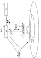
FIG. 1 is a diagram (#1) showing a system
configuration example applicable to each embodiment
of the present invention.
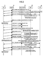
FIG. 2 shows a sequence in a wireless
communication system according to a first embodiment
of the present invention for establishing a user
data channel, and finally the channel is changed
from a UTRAN channel to a wireless LAN channel.
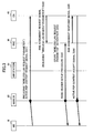
FIG. 3 shows details of a PDP context
processing procedure in the sequence shown in FIG. 2,
and shows a flow therein carried out until a
wireless LAN request parameter reaches an RNC.
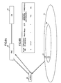
FIG. 4 illustrates creation of an IP
address usable only in a wireless LAN environment
for an MS with a DHCP function of a radio air
station in the sequence shown in FIG. 2.
FIG. 5 illustrates "wireless LAN
available" notification with the use of a
conventional UTRAN channel from an MS to an RNC.
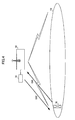
FIG. 6A illustrates a flow of
communication information from the MS to the RNC in
the sequence shown in FIG. 2.
FIG. 6B illustrates "mobile terminal
information correspondence table" created and held
by the RNC from information obtained through
communication operation shown in FIG. 6A.
FIG. 7 illustrates channel switching in a
path unit with reference to the "mobile terminal
information correspondence table" in the sequence
shown in FIG. 2.
FIG. 8 illustrates a packet format at a
time of user data transfer through the wireless LAN
channel in the sequence shown in FIG. 2.
FIG. 9 is a diagram (#2) showing a system
configuration example applicable to each embodiment
of the present invention.
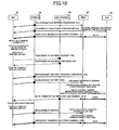
FIG. 10 shows a sequence in a wireless
communication system according to a second
embodiment of the present invention for establishing
a user data channel, and finally the channel is
changed from a UTRAN channel to a wireless LAN
channel.
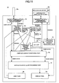
FIG. 11 shows a functional block diagram
of a mobile terminal applicable to each embodiment
of the present invention.
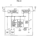
FIG. 12 shows a hardware configuration of
a mobile terminal applicable to each embodiment of
the present invention.
FIG. 13 shows a sequence in a wireless
communication system according to a fourth
embodiment of the present invention for establishing
a user data channel and a flow of subsequent
processing.
FIG. 14 shows a sequence in a wireless
communication system according to a fifth embodiment
of the present invention for establishing a user
data channel and a flow of subsequent processing.
BEST MODE FOR CARRYING OUT THE PRESENT INVENTION
Embodiments of the present invention are
described below in details.
The embodiments belong to a mobile
communication system of 3GPP which is a project
group involved for creating a specification of a so-called
third generation mobile communication system
'IMT2000', and have a configuration shown in FIG. 1,
for example.
The mobile communication system generally
includes a radio access network (UTRAN) and a core
network apparatus (CN) 40 which controls position
control, call control and service control, and the
radio access network UTRAN includes a base station
control apparatus (RNC) 30 and a node B 20 acting as
a radio base station.
The core network apparatus 40 and the base
station control apparatus 30 are connected by a so-called
Iu (interconnection point) interface, and the
base station control apparatus 30 carries out
management of radio resources, control of the
respective nodes B 20, and so forth. Each node B 20
covers one or a plurality of cells, and covers a
region of an area R1 in an example of FIG. 1.
On the other hand, the base station
control apparatus 30 is connected to an air station
50 used for providing a spot manner communication
service with the use of predetermined wireless LAN
via a router 60 via a communication network such as
an Ethernet (registered trademark). The air station
50 has a DHCP (dynamic host configuration protocol)
server 70, and has a DHCP function for providing an
IP address automatically to a terminal 10 belonging
thereto. An area covered by annunciation radio
waves of the air station 50 is a region R2 in the
example of FIG. 1.
Each mobile terminal 10 possessed by a
user is, for example, a cellular phone, is connected
to a predetermined wireless communication channel
with the node B 20 when the mobile terminal exists
within the area R1 covered by the node B 20, while
it is connected similarly with a predetermined
wireless communication channel via the air station
50 when the mobile terminal exists within the area
R2 covered by the air station 50 of wireless LAN.
There, the mobile terminal carries out ordinary
speech communication or packet communication with a
small transmission data amount in communication via
the node B 20, while it carries out high rate large
size packet communication with a relatively large
transmission data amount in communication via the
air station 50 of wireless LAN.
Communication control operation carried
out in the present configuration is roughly
described below.
That is, the mobile terminal 10 requests
the DHCP server 70 which provides an IP address when
receiving radio waves from the side of the wireless
LAN. Then, the terminal 10 transmits the IP address
thus obtained from the side of the wireless LAN, to
the radio base station 30 after attaching the IP
address to a "receiving radio wave condition report
(Measurement Report)" signal as new reporting
information called a temporary IP address parameter.
Further, a user of this terminal 10 may incorporate
a "wireless LAN request parameter" into context
information through operation made on the terminal
when communication is started up.
On the other hand, the core side apparatus
40 which receives active PDP context request signal
information notifies the relevant base station
control apparatus 30 of the above-mentioned
"wireless LAN request parameter" included therein as
a new information element of a RAB assignment
request signal. The base station control apparatus
30 stores 'terminal identifier - temporary IP
address - communication path context information' in
a predetermined "mobile terminal information
correspondence table", and refers to a relevant
position of the table in response to receiving the
"receiving radio wave condition report (Measurement
Report)" from the terminal 10 as a trigger.
The base station control apparatus 30
determines whether or not a communication channel
should be switched based on a result of the
referring to the "mobile terminal information
correspondence table". Then, when the channel is
switched to that using wireless LAN, user data is
converted into a form of IP over IP, includes the IP
address obtained in the wireless LAN environment in
an outer header, and sends it out.
Further, the base station control
apparatus 30 sends an IP address of its own to the
terminal 10 in a form of new information including
it in a "measurement stop instruction (Measurement
completion)".
By such processing, the terminal 10
obtains the new IP address in the environment in
which wireless LAN is available from the DHCP server
70, notifies the same to the base station control
apparatus 30, which then uses this IP address as a
destination address and carries out communication
with the terminal 10 via a new radio channel which
is a wireless LAN channel.
Further, the terminal 10 attaches the IP
address obtained in the wireless LAN environment as
new parameter information of the "receiving radio
wave condition report (Measurement Report)", and it
can send this information to the base station
control apparatus 30 with the use of the existing
signal.
Further, by means of designating a
"wireless LAN request parameter" through terminal's
operation at a time of communication starting up, a
terminal's user can determine whether the user
wishes to use the wireless LAN channel, for each
unit of communication contents. Further, by
attaching this parameter as new context information,
it is possible to transmit this information to the
side of the network with the use of the existing
signal (active PDP context request).
The core side apparatus 40 which receives
this active PDP context request signal then attaches
the "wireless LAN request parameter" included
therein as a new information element of the existing
signal (RAB assignment request), and sends the same
to the base station control apparatus 30. As a
result, the request of the subscriber input from the
terminal 10 is stored in the base station control
apparatus 30 as context information.
Then, the base station control apparatus
30 has the "mobile terminal information
correspondence table", collectively manages all the
information concerning a data path established with
the terminal 10 therein, and thus, the base station
control apparatus 30 itself can determine whether or
not channel switching is needed. Further, reception
of the "receiving radio wave condition report
(Measurement Report)" signal is used as a trigger
for referring to this correspondence table. As a
result, it is possible to start up operation of
distributing data to an appropriate channel at an
appropriate timing.
Further, as the IP address obtained in the
wireless LAN environment by the terminal 10 is
transmitted therefrom as header information outside
of a packet encapsulated in an IP-over-IP form, this
is used for applying the wireless LAN as a
communication channel, and a session between the
base station control apparatus 30 and the terminal
10 can be established.
Thus, the wireless LAN environment
available to the terminal 10 is notified of, to the
base station control apparatus 30 which exists in
the IP communication network with mobility, and
thereby it is possible to make a determination for
changing a data path of user data provided via a
predetermined path to be then transferred via a
wireless LAN channel. As a result, it is possible
to change a user data communication channel between
the base station control apparatus 30 and the
terminal 10, into a wireless LAN channel, as is
necessary. Accordingly, it is possible to
incorporate a high rate communication function of
wireless LAN originally carried out independently
from mobile communication, into a IP communication
network with mobility in a seamless manner, and to
provide a spot manner high rate communication
service in the framework of a mobile communication
network service.
In the above-mentioned configuration, the
accessing function which is an original function of
the mobile communication network normally is
utilized, and, thereby, it becomes possible to
automatically switch into data communication via
wireless LAN when a user moves to the area S2 in
which wireless LAN is available. In this case, the
user who wishes to use data communication on
wireless LAN may always activate a wireless LAN
device mounted in the mobile terminal 10 regardless
of whether or not it exists within the wireless LAN
service providing area S2.
In this case, the wireless LAN device
receives all the radio frames transmitted from the
air station of wireless LAN regardless of whether or
not they are addressed to it, as long as it exists
within the above-mentioned area S2. Then, at each
time, it examines each of the received frames for a
destination MAC address thereof. Accordingly, a
power consumption amount in the mobile terminal 10
may increase.
Further, when the user exists within the
wireless LAN service providing area S2 and carries
out data transmission/reception, data
transmission/reception may be carried out always
with the use of the communication system on wireless
LAN even if a data amount is relatively small so
that a circuit capacity prepared by the
communication system on wireless LAN may be surplus
while a circuit capacity of the accessing means of
the original mobile communication network may be
sufficient. In this case, since power consumption
of the wireless LAN device is larger than that for a
case of communication operation on the original
mobile communication network, the power may be
uselessly consumed in the mobile terminal 10.
On the other hand, since the mobile
terminal 10 used in communication on the mobile
communication network operates with a battery
mounted therein, increase in the power consumption
results in reduction of a stand-by duration, whereby
usage inconvenience may arise. Therefore, in the
above-mentioned 3GPP, mobile terminals are grouped
into some receiving groups, and, a notification of
signal reception is sent to a specific receiving
group with the use of a PICH (page indication
channel: a type of physical channel). Mobile
terminals which receive the notification of signal
reception on the PICH receive a PCH (paging channel:
a type of transport channel) mapped to a S-CCPCH
(secondary common control physical channel: a type
of physical channel). At this time, the mobile
terminals in stand-by modes receive only a PI
(paging indicator) addressed to the receiving group
to which they belong, and receive the S-CCPCH/PCH
only when receiving the notification of signal
reception. Accordingly, power consumption at a time
of signal reception is effectively reduced, and as a
result, power consumption in the mobile terminal is
reduced. Details of the system are disclosed by,
for example, 'W-CDMA mobile communication system',
under editorship of Keiji Tachikawa, published by
Maruzen Co., Ltd., the fourth edition, pages 222-223,
'(ii) intermittent receiving control' or such.
There, an electric current is consumed during on the
order of 10 ms for each radio frame of the above-mentioned
PICH.
On the other hand, in a communication
system of wireless LAN, between an access point and
a transmission/reception terminal belonging thereto,
all radio waves are transmitted/received via a
single channel. Then, for the purpose of avoiding
radio wave competition (frame collision), a scheme
of CSMA/CA+ACK (carrier sense multiple access with
collision avoidance with acknowledgement), RTS/CTS
(request to send/clear to send) or such is applied.
In the CSMA/CA+ACK scheme, there is a case where a
transmission side transmits radio waves to a
receiving side without advance notice. Further, in
the above-mentioned RTS/CTS scheme, data
transmission is carried out after a transmission
side carries out RTS (transmission advance
notification) and receives CTS (reception
acceptance), where the RTS or CTS is received by all
the terminals. Accordingly, in either scheme, the
transmission/reception terminals should always be in
a condition in which they can receive radio waves,
and therefore, power consumption amounts increase in
the terminals. The above-mentioned technology of
radio wave competition is disclosed by, for example,
'Nikkei NETWORK, September, 2000', pages 66-67, 'How
radio wave competition is avoided?', or such.
Thus, a technology of reducing the power
consumption in the terminal is applied in a
communication system of mobile communication network.
However, such a technology has not been established
in a wireless LAN communication system yet.
Therefore, if a communication system on wireless LAN
is incorporated in and is applied to an existing
communication system on a mobile communication
network as it is, the above-mentioned imbalance in
power consumption may result in increase of the
power consumption of particular mobile terminal, a
stand-by duration available from single battery
charge remarkably drops, and thereby, inconvenience
may arise.
In the embodiments of the present
invention, in consideration of the above-mentioned
problems, the power consumption is reduced as a
result of carrying selective switching of data
communication from a mode using mobile communication
accessing means to a mode using wireless LAN, a
working duration for which a user uses the mobile
terminal with power supply from the battery is
increased, and thus, the convenience is improved.
Specifically, as described above, in
wireless data communication on wireless LAN, radio
frames reach all the radio terminals existing within
the radio wave reachable area. The mobile terminal
which receives the radio waves then compares
destination MAC addresses of all the radio frames
with its own MAC address, discards the radio frames
having the different addresses as a result of the
comparison, and takes only the radio frame addressed
thereto. Thus, since it always carries out the
reception and the comparison even on the radio
frames having the different addresses, the power
consumption may remarkably increase in a state of
using a wireless LAN service in comparison to the
other states. Accordingly, if a manner of always
activating the wireless LAN device regardless of
whether or not data communication is carried out is
applied, the power consumption increases.
In order to solve the problem, in the
embodiments of the present invention, the way of
always entering the wireless LAN available condition
when the mobile terminal moves to the wireless LAN
available area is avoided, switching of data
communication from a service using the mobile
communication accessing means to a service using
wireless LAN is carried out selectively, and thereby,
the power consumption in each terminal is reduced.
As a result, a working duration for which a user
uses the mobile terminal with the power supply from
the battery is increased, and thus, convenience can
be improved.
Specifically, in the embodiments of the
present invention, even when the mobile terminal 10
exists within the wireless LAN service available
area S2, the wireless LAN device mounted in the
mobile terminal 10 is left inactivated, i.e., in a
state without the power supply when data
transmission/reception is not actually carried out,
while a function of determining whether or not data
transmission/reception on wireless LAN should be
carried out is provided in the user, the mobile
terminal itself or in the mobile communication
network.
As a criterion of the determination, a
data transmission/reception amount, remaining
battery power, a mobile communication
network/wireless LAN radio link band vacancy
situation, or such, or a combination thereof is
applied. Then, the user, the mobile terminal or the
mobile communication network determines that data
transmission/reception on wireless LAN should be
carried out, and wireless LAN is activated, i.e., is
fed with power only when data transmission/reception
on wireless LAN is actually carried out whereby
transmission/reception of radio waves and check of
received MAC frame destination can be carried out.
Then, when the data transmission/reception is
finished, the wireless LAN device is again
deactivated manually or automatically.
By configuring so, the wireless LAN device
is activated only when it is necessary, while it is
deactivated when it becomes not necessary. Thereby,
it is possible to control the power consumption of
the mobile terminal on the minimum necessary level.
Thereby, it is possible to increase the battery
working duration of the mobile terminal, and thus,
it is possible to keep the convenience of the
conventional mobile communication system even
incorporating the wireless LAN system.
As described above, the communication
system according to the embodiments of the present
invention includes the mobile terminal 10, the base
station control apparatus 30, the radio base station
20, the air station 50 providing wireless LAN
service, and the core network apparatus 40.
Configuration of each apparatus in a first
embodiment of the present invention is described
next. In the first embodiment, based on a
communication data amount occurring when data is
downloaded in the mobile terminal 10, switching
between data transfer via UTRAN, i.e., the
conventional mobile communication network and data
transfer on wireless LAN may be carried out.
First, configuration of the mobile
terminal 10 is described. The mobile terminal has
an IP communication function via UTRAN and an IP
communication function via wireless LAN. Further,
the mobile terminal 10 previously has an IP address
for the purpose of communication in an end-to-end
manner. This IP address is used for IP
communication either via UTRAN or via wireless LAN.
Further, the mobile terminal 10 has a
function of attaching information that a user wishes
data communication on wireless LAN to PDP context
information and notifying the base station control
apparatus 30 thereof. The information used for this
notification is referred to as a "wireless LAN
request parameter". Further, the mobile terminal 10
has a function of attaching a "threshold value" used
when a communication state is switched from one via
UTRAN to one via wireless LAN, to the above-mentioned
PDP context information, and notifying the
base station control apparatus 30 thereof. However,
the above-mentioned threshold value may be fixedly
set as a common value among all the mobile terminals
10 belonging to the base station control apparatus
30. In this case, the above-mentioned notification
function is not required.
Further, the mobile terminal 10 has a
function of responding to an instruction (signal)
from the base station control apparatus 30 for
turning on/off the power supply to the wireless LAN
device mounted therein. The mobile terminal 10 has
a function of receiving radio waves from the air
station 50 to determine that communication via
wireless LAN is available, after turning on the
power supply to the wireless LAN device responding
to the instruction from the base station control
apparatus 30.
Before carrying out communication via
wireless LAN, the mobile terminal 10 obtains an IP
address via the air station of wireless LAN thanks
to the DHCP function provided in the air station 50.
This IP address is different from the above-mentioned
IP address previously given for the
purpose of end-to-end communication, is used for
setting a transport layer between the base station
control apparatus 30 and the mobile terminal 10, and
is referred to as a temporary IP address.
The mobile terminal 10 further has a
function of notifying the base station control
apparatus 30 of the temporary IP address with the
use of the receiving radio wave condition report
(Measurement Report) signal conventionally used in
UTRAN via the radio base station 20 (via the
conventional UTRAN). Further, the mobile terminal
10 has a function of, when the mobile terminal 10
moves to the outside of the wireless LAN service
area S2, notifying the base station control
apparatus 30 of this situation with the use of the
receiving radio wave condition report (Measurement
Report) signal in which 'blank' is set in the
temporary IP address field. Further, the mobile
terminal 10 has a function of, when the power supply
to the wireless LAN device mounted in the mobile
terminal 10 is turned off, notifying the base
station control apparatus 30 of this situation with
the use of the receiving radio wave condition report
(Measurement Report) signal in which 'blank' is set
in the temporary IP address field.
Next, configuration of the base station
control apparatus 30 is described. The base station
control apparatus 30 has an IP communication
function on a UTRAN channel. In other words, the
base station control apparatus 30 has a function of
recognizing a radio environment under which the
mobile terminal 10 can carry out
transmission/reception, from the above-mentioned
receiving radio wave condition report (Measurement
Report) signal. This is a function which the
conventional base station control apparatus
according to 3GPP has.
The base station control apparatus 30 has
an IP address for communication on wireless LAN
given. This IP address corresponds to the above-mentioned
temporary IP address on the side of the
mobile terminal 10. Further, the base station
control apparatus 30 has a function of receiving the
temporary IP address included in the receiving radio
wave condition report (Measurement Report) signal
from the mobile terminal 10.
Further, the base station control
apparatus 30 has a function of receiving the above-mentioned
"wireless LAN request parameter" included
in the active PDP context request signal from the CN
40. The base station control apparatus 30 has a
function of receiving a "threshold value" for
switching to communication on wireless LAN, from the
mobile terminal 10 as a part of the above-mentioned
receiving radio wave condition report (Measurement
Report) signal, and holding this value. As
mentioned above, the threshold value may be fixedly
set on the side of the base station control
apparatus 30 previously instead of receiving it from
the mobile terminal 10. Further alternatively, the
threshold value may be previously registered in a
database of the core network apparatus (CN) 40 as
subscriber data, and the base station control
apparatus 30 may download the same from the database.
The base station control apparatus 30 has
a function of producing and managing a
correspondence table among a predetermined "mobile
terminal identifier (ID of MS)", "temporary IP
address", "allocated radio channel (Radio Bearer)",
"GTP", "context (wireless LAN request)" and
"threshold value". This correspondence table is
referred to as the "mobile terminal information
correspondence table".
Further, the base station control
apparatus 30 has a control part and a user data
transfer part. The control part has a function of
referring to the above-mentioned mobile terminal
information correspondence table, carrying out
processing described below, thereby determining
which channel of a UTRAN chancel or a wireless LAN
channel user data should be sent out through, and
providing an instruction to the user data transfer
part for the channel switching. Further, the
control part in the above-mentioned base station
control part has a function of sending out a signal
providing an instruction to the mobile terminal 10
to turn on the power supply to the own wireless LAN
device when detecting that a data amount addressed
to this mobile terminal 10 having a wireless LAN
communication function exceeds a predetermined
threshold value. The control part has a function of
sending out a signal providing an instruction to the
mobile terminal 10 to turn off the power supply to
the own wireless LAN device when detecting that the
data amount drops from the predetermined threshold.
Further, when receiving a notification
that the mobile terminal becomes able to carry out
communication via wireless LAN by the receiving
radio wave condition report (Measurement Report)
signal from the mobile terminal 10 to which the
signal for turning on the power supply to the
wireless LAN device is sent, the control part in the
base station control apparatus 30 sends a
communication switching instruction such that user
data transmission to the mobile terminal 10 will be
carried out via wireless LAN, to the user data
transfer part. On the other hand, if the control
part in the base station control apparatus 30 has
not received the notification that communication via
wireless LAN becomes available when a predetermined
duration has elapsed after the instruction for
turning on the power supply to the wireless LAN
device was sent to the mobile terminal 10, the
control part in the base station control apparatus
30 determines that the mobile terminal 10 exits the
wireless LAN service area S2, and transmits a signal
providing an instruction to this mobile terminal 10
to turn off power supply to the wireless LAN device.
Until receiving the notification of the receiving
radio wave condition report (Measurement Report)
signal from the mobile terminal 10 that
communication via wireless LAN becomes available,
the base station control apparatus 30 transmits user
data to the MS 10 via the radio base station 20,
i.e., via UTRAN in the conventional manner
The above-mentioned user data transfer
part in the base station control apparatus 30 has a
function of terminating a GTP which is a channel
from the CN 40 and a channel via UTRAN and via
wireless LAN for the MS 10, and switching a transfer
channel between one via UTRAN and one via wireless
LAN when transferring user data received from the CN
40 based on an instruction from the control part.
Further, the base station control apparatus 30
transmits/receives a control signal to/from the
mobile terminal 10 via the radio base station 20
(via UTRAN) in a conventional manner, without regard
to the above-mentioned user data transfer channel.
Next, a configuration of the radio base
station 20 is described. The radio base station 20
has an IP communication capability via UTRAN, and
has a function of sending user data and a control
signal received from the mobile terminal 10 to the
base station control apparatus 30 or sending user
data and a control signal received from the base
station control apparatus 30 to the mobile terminal
10. These functions are those which a radio control
apparatus belonging to UTRAN according to the
conversional 3GPP has.
A configuration of the air station 50 of
wireless LAN is described next. This wireless LAN
air station 50 has an interface for the base station
control apparatus 30, and can repeat user data
transmitted from the base station control apparatus
30 for the mobile terminal 10. In other words, the
interface between the air station and the base
station control apparatus 30 has a user data
transfer function, and has a function as an agent
for transferring user data between the mobile
terminal 10 and the base station control apparatus
30. In other words, it has a conversion function
between a frame format on a wired interface
(Ethernet (registered trademark) or such) and a
frame format on wireless communication (wireless
LAN).
Further, the air station 50 is connected
with the DHCP server 70, and has a function of
automatically providing an IP address (corresponding
to the above-mentioned temporary IP address) to the
mobile station belonging thereto.
A configuration of the core network
apparatus 40 may be same as the configuration of a
core network apparatus in a conventional mobile
communication system according to the 3GPP, where
functions of subscriber management, movement
management and so forth are utilizable as they are.
A communication sequence according to the
present invention is described next with reference
to FIGS. 2 through 8. In FIG. 2, solid lines denote
flow of signal transmission via conventional UTRAN,
while broken lines denote flow of signals via
wireless LAN. Further, according to device names
prescribed in the 3GPP, the above-mentioned mobile
terminal 10, the base station control apparatus 30,
the radio base station 20 and the core network
apparatus 40 connected with the base station control
apparatus 30 are referred to as 'MS', 'RNC', 'node
B' and 'CN' (generic term), respectively.
In FIG. 2, in Step S1, when data is
received by/transmitted from the MS 10, an RRC
connection setting procedure for establishing a
control signal channel is executed between the RNC
30 and the MS 10. It is processing defined in the
European Standard of a third generation mobile
communication system 'IMT2000' defined by the
conventional UMTS, i.e., the European Electricity
and Communication Standardization Society, and the
present procedure is prescribed in the 3GPP
specification, TS25.331.
Then, in Step S2, for the purpose of
setting a user data channel, a PDP context
processing procedure is executed. Details of this
processing procedure are shown in FIG. 3, are
defined by the above-mentioned UMTS, and are
prescribed in the 3GPP specification, TS23.060.
According to the present embodiment, as the context
information prescribed for this procedure, the
above-mentioned 'wireless LAN request parameter' is
newly added (Step S31 in FIG. 3). AS a result of
this PDP context processing procedure being executed,
a pipe called a GTP is established for the purpose
of transferring user data.
As a result of the 'wireless LAN request
parameter' being added as one information element of
the RAB assignment request (Step S32) prescribed to
be sent to the RNC 30 from the CN 40 in this
processing procedure, this parameter is sent to the
RNC 30, and, there, is stored as one element of the
context information (Step S33). Also, as the user
data channel between the RNC 30 and the MS 10, an
allocated radio channel (Radio Bearer) is
established (Step S34) .
Then, in Step S3, the GTP and the
allocated radio channel (Radio Bearer) thus
established are used, and user data transmission is
carried out via the conventional UTRAN (via the node
BG 20). AT this time, the above-mentioned user
transfer part in the RNC 30 sends the user data
received from the CN 40 to the UTRAN channel,
whereby the user transmission to the MS 10 is
achieved.
In Step S4, the RNC 30 monitors a data
amount (traffic) by which the MS 10 receives. In
this processing, a result of monitoring processing
carried out by the RNC 30 for the purpose of
switching of allocation of a channel to be used
between a common channel and an individual channel
according to the data amount, which processing is
one according to the conventional 3GPP specification,
is utilized.
Then, in Step S5, the RNC 30 determines
continuously whether or not the data amount
(traffic) obtained by the above-mentioned processing
exceeds a predetermined threshold. This threshold
may be one previously set fixedly by the RNC 30, or
may be one included in the information notified of
by the MS 10 to the RNC 30 via the CN in the PDP
context processing procedure in Step S2.
Then, in Step S6, when the RNC 30
determines that the data amount (traffic) exceeds
the threshold in Step S5, the RNC 30 provides an
instruction to the MS 10 for turning on the wireless
LAN device thereof via a control signal route of
UTRAN (via the node B 20). Specifically, this can
be achieved as a result of adding this signal to the
conventional specification of the individual control
channel (Dedicated Control Channel, i.e., DCCH).
In Step S7, when receiving the instruction
of Step S6, the MS 10 turns on the own wireless LAN
device, and receives a signal from the air station
50. Then, in Step S8, the MS 10 requests the DHCP
server 70 in the air station 50 for a temporary IP
address (see FIG. 4).
In Step S9, the wireless LAN air station
50 provides a temporary IP address to the MS 10.
This temporary IP address is used as an IP address
on the side of the MS 10 used for achieving the
transport layer used when communication of user data
via wireless LAN is carried out between the RNC 30
and the MS 10, and, as described above, is different
from an IP address used in the end-to-end
communication by the MS 10.
Then, in Step S10, the RNC 30 sends the
above-mentioned receiving radio wave condition
request (Measurement Request) signal to the MS 10.
This is a function which is provided conventionally
in an RNC according to the 3GPP, and, actually, is
transmitted periodically to the MS 10.
In Step S11, the MS 10 includes the
temporary IP address obtained in Step S9 in the
receiving radio wave condition report (Measurement
Report) signal, which is a response to the above-mentioned
receiving radio wave condition request
(Measurement Request) signal, and sends it to the
RNC 30. As a result, the RNC 30 recognizes that the
MS 10 is in a state of being able to use wireless
LAN (see FIG. 5).
On the other hand, in a case where the MS
10 is outside of the wireless LAN service area R2,
since it cannot receives the temporary IP address in
Step S9, the MS 10 cannot add the temporary IP
address to the receiving radio wave condition report
(Measurement Report) signal to be returned to the
RNC 30 for notifying it thereof (Step S11A).
Then, in Step S12, when the temporary IP
address is not included in the receiving radio wave
condition report (Measurement Report) signal
received from the MS 10 until a predetermined
duration has elapsed since the instruction to turn
on the wireless LAN of the MS 10 was sent out, the
RNC 30 determines that the MS 10 is outside of the
wireless LAN service area R2, and provides an
instruction to the MS 10 to turn off the power
supply to the wireless LAN thereof.
Then, in Step S13, when receiving the
instruction to turn off the power supply to the
wireless LAN device from the RNC 30 in Step S12, the
MS 10 turns off the power supply to the own wireless
LAN device, and continues data reception via UTRAN.
Further, the RNC 30 produces and manages
the above-mentioned mobile terminal information
correspondence table (Step S14). This mobile
terminal information correspondence table has a
configuration, for example, as that shown in FIG. 6B,
and includes "mobile terminal identifier (ID of MS)",
"temporary IP address", "allocated radio channel
(Radio Bearer)", "GTP", "context (wireless LAN
request)", and "threshold".
In Step S15, based on the mobile terminal
information correspondence table produced in Step
S14, the RNC 30 determines whether or not it is
necessary to switch the data transfer channel to a
wireless LAN channel. Specifically, the control
part in the RNC 30 determines for the relevant
mobile terminal that it is necessary to switch the
channel when the data communication amount for the
mobile terminal for which "wireless LAN request
parameter" and the "temporary IP address" are
included in the mobile terminal information
correspondence table exceeds the above-mentioned
threshold, and provides an instruction to the user
data transfer part in the RNC 30 to switch to the
wireless LAN channel.
In this case, in Step S16, the data
transfer part in the RNC 30 transmits user data to
the temporary IP address, and thereby, the user data
transmission via wireless LAN is achieved. That is,
as shown in FIG. 7, the user data channel is
switched to the data channel from the wireless LAN
air station. Thus, as shown in FIG. 8, the user
data is transferred to the relevant MS 10 on the
wireless LAN channel.
On the other hand, according to the
conventional 3GPP specification, when a data
communication amount of an individual channel
decreases, a communication channel of a relevant
mobile terminal is switched automatically to a
common channel. According to the present embodiment,
according to this specification, the allocated radio
channel (Radio Bearer) set in Step S3 is held even
after the user data channel is switched to that via
wireless LAN as mentioned above. A time interval is
required until switching is carried out for the
allocated radio channel (Radio Bearer) from the
individual channel to the common channel after the
communication channel was switched to the wireless
LAN according to the 3GPP specification as it is.
Therefore, it is preferable to provide a
configuration such that, the allocated radio channel
(Radio Bearer) is forcibly switched into the common
channel from the individual channel immediately
after the communication channel switching to the
wireless LAN for the user data occurs.
Further, in Step S17, the RNC 30 continues
monitoring of the data amount (traffic) started in
Step 4, and determines whether or not the data
amount (traffic) drops from the threshold described
for Step S5. Then, in Step S18, when the RNC 30
detects that the data amount drops from the
threshold, the RNC 30 returns the user data
communication channel to the channel via the
allocated radio channel (Radio Bearer) held in Step
S16. In this case, in Step S19, at a time when the
channel switching has completed in Step S18, the RNC
30 provides an instruction to the MS 10 via the
control signal route of UTRAN (via the node B) to
turn off the power supply to the wireless LAN device
of the MS 10. Then, in this case, in Step S20, the
RNC 30 updates the mobile terminal information
correspondence table produced in Step S14, and
deletes the value in the "temporary IP address"
field. Thereby, in Step S21, the MS 10 turns off
the power supply to the own wireless LAN device when
receiving the instruction of Step S19.
Through the above-described operation,
only when a large size of user data is received, for
which a data transmission rate would be not
sufficient by a conventional data transfer channel
via UTRAN (via the node B), switching is made to a
data transfer channel by wireless LAN, whereby user
data communication is carried out. Furthermore,
only when the wireless LAN is used, the power supply
to the wireless LAN device of the relevant mobile
terminal 10 is turned on. As a result, it is
possible to effectively reduce the power consumption
in the relevant terminal.
According to the present embodiment, the
MS 10 receiving the control signal from the RNC 30
automatically turns on/off the power supply to the
own wireless LAN device. However, instead, a
configuration may be made such that the MS 10
receiving the control signal may display the
information on a display device or such, thereby,
the user of the MS 10 may recognize this, as a
result the user may determines whether or not a
communication channel should be switched, and may
turn on/off the power supply to the wireless LAN
device manually.
According to the present embodiment, the
allocated radio channel (Radio Bearer) set in Step 3
is held even after the user data channel is switched
to that via wireless LAN. However, instead, when
the user data channel is switched to that via
wireless LAN, the above-mentioned allocated radio
channel (Radio Bearer) may be disconnected, and,
when the communication via the wireless LAN has been
completed, the allocated radio channel (Radio
Bearer) may be set again.
Further, according to the present
embodiment, the temporary IP address is given by the
DHCP server accompanying the air station 50, to the
mobile terminal. However, other than this, an
individual DHCP server may be set in a network such
as an Ethernet (registered trademark) between the
air station 50 and the router 60.
Further, according to the present
embodiment, in the system configuration, as shown in
FIG. 1, the single air station 50 provides wireless
LAN service. However, other than this, as shown in
FIG. 9, a plurality of air stations 51, 52, and 53
may be used to provide the service for the area R2.
Furthermore, for a region located
geographically away from the router shown in FIG. 1
or 9, segmentation may be carried out for segments,
and, for each segment, a network number of an IP
address may be changed, wherewith wireless LAN
service may be provided thereto.
As one example of a specific method of
turning on the power supply to the wireless LAN
device mounted in the mobile terminal 10, a method
may be considered by which a function of 'adding
hardware' in a "control panel" mounted as a standard
item in Windows 9x.ME or such (any one being a
registered trademark) may be automatically executed,
whereby the wireless LAN device may be detected, and
may be started up. Further, by executing a
'hardware dismantling' function in a PC card may be
executed, the power supply to the relevant wireless
LAN device may be turned off.
Next, a second embodiment of the present
invention is described. The second embodiment has
the same configuration as that of the first
embodiment. Accordingly, detailed description will
be made only for parts different from those in the
first embodiment. According to the present
embodiment, the user who uses the mobile terminal 10
manually switches a data transfer channel between
UTRAN and wireless LAN if necessary based on a data
amount (traffic) displayed on the relevant mobile
terminal 10. In other words, the user of the mobile
terminal determines, based on the data amount to
download, whether the data is to be downloaded in
communication either via a channel on UTRAN or via a
channel on wireless LAN, and as a result, the user
carries out operation to switch the communication
channel if necessary.
According to the present embodiment, the
function of notifying the base station control
apparatus 30 of the threshold for switching into
communication with wireless LAN after attaching it
to the PDP context information is not necessary.
Further, a configuration is provided such that, when
the user carries out a necessary operation on the
mobile terminal 10 after determining to receive data
via wireless LAN or finish the reception, the power
supply to the wireless LAN device mounted in the
mobile terminal 10 is automatically turned on/off in
response to the relevant operation.
Further, when the power supply to the
wireless LAN device is turned on as a result of the
operation being carried out by the user, the mobile
terminal 10 determines that communication via
wireless LAN is available as a result of receiving
radio waves from the air station 50. On the other
hand, when no radio waves can be received from the
air station 50, the mobile terminal 10 determines
that it exists outside of the wireless LAN service
area R2, notifies the user of this matter, and turns
off the power supply to the own wireless LAN device.
Further, according to the present
embodiment, the function of the base station control
apparatus 30 to hold the threshold value when
receiving the above-mentioned threshold value for
switching into communication on wireless LAN in a
form of being included in the receiving radio wave
condition report (Measurement Report) signal is not
necessary. Furthermore, the function of determining
which channel between UTRAN and wireless LAN should
be applied for sending out user data is not
necessary.
Also, according to the present embodiment,
the function of the control part of the base station
control apparatus 30 of sending out the signal
providing an instruction to turn on the power supply
to the wireless LAN device to the mobile terminal 10
when detecting that the data amount for the mobile
terminal 10 having the communication function of
wireless LAN exceeds the predetermined threshold is
not needed. Furthermore, the function of sending
out the signal providing an instruction to turn off
the power supply to the wireless LAN device to the
mobile terminal when detecting that the data amount
drops from the predetermined threshold is not needed.
According to the present embodiment, the
base station control apparatus 30 has a function of
providing an instruction to the user data transfer
part for switching a communication channel for
carrying out transmission of user data to the mobile
terminal 10 via wireless LAN, when receiving from
the mobile terminal 10 a notice that communication
via wireless LAN is available in a form of being
included in the receiving radio wave condition
report (Measurement Report) signal.
A communication sequence of the second
embodiment is described with reference to FIG. 10.
First, the same as in the first embodiment,
in Step S1, when data is received by/transmitted
from the MS 10, the RRC connection setting procedure
for establishing a control signal channel is
executed between the RNC 30 and the MS 10. Then, in
Step S2, for the purpose of setting a user data
channel, the PDP context processing procedure is
executed. As the context information prescribed,
the 'wireless LAN request parameter' is newly added,
and as a result of this PDP context processing
procedure being executed, a pipe called a GTP is
established for the purpose of transferring user
data between the RNC 3 and the CN 40. As one
information element of the RAB assignment request
sent from the CN 40 to the RNC 30 in this processing
procedure, the "wireless LAN request parameter" is
added, and thereby, this parameter information is
stored as one information element of the context
information in the RNC 30, and also, the allocated
radio channel (Radio Bearer) as a user data channel
between the RNC 30 and the MC 10 is established.
With the use of the thus-established GTP
and the allocated radio channel (Radio Bearer), user
data communication on a conventional UTRAN channel
(via the node B) is carried out. At this time, the
data transfer part in the RNC 30 sends the user data
received from the CN 40 to the UTRAN channel, and
data transmission to the MS 10 is achieved.
At this time, the user of the mobile
terminal 10 can access an FTP server, and as a
result, in Step S41, the MS 10 displays a size of
data which the user wishes to download thanks to a
common function such as a Web browser or such. In
Step S42, the user determines whether or not a data
communication channel should be switched to wireless
LAN for this purpose, based on the data amount to
download, displayed on the MS 10. Then, when the
user determines to switch the communication channel,
the user carries out the operation for switching on
the MS 10.
In response to this operation, the MS 10
turns on the power supply to the wireless LAN device
as mentioned above in Step S43, and therewith
receives radio waves from the air station 50.
Then, in Step S8, the same as in the first
embodiment, the MS 10 requests the DHCP server 70 of
the air station 50 for a temporary IP address. The
air station 50 responds thereto, and provides a
temporary IP address to the MS 10 in Step S9.
Then, when the MS 10 cannot receive a
temporary IP address even after a predetermined
duration has elapsed since the temporary IP address
request was made in Step S8, it determines that it
exists outside of the wireless LAN service area R2.
As a result, in Step S44, the MS 10 notifies the
user that it exists outside of the wireless LAN
service area R2, turns off the power supply to the
own wireless LAN device, and continues data
reception on the UTRAN channel set in Step S3.
Further, the same as in the first
embodiment, in Step S10, the RNC 30 sends the
receiving radio wave condition request (Measurement
Request) signal to the MS 10 periodically. In Step
S45, the MS 10 transmits the temporary IP address
obtained in the above-mentioned step to the RNC 30
after including it in a propagation condition report
(Measurement Report) signal which is a response to
the receiving radio wave condition request signal.
As a result, the RNC 30 recognizes that the MS 10 is
in an environment to be able to use wireless LAN.
Then, in Step S14, the same as in the
first embodiment, the RNC 30 produces and manages
the mobile terminal information correspondence table.
In this mobile terminal information correspondence
table, respective information of 'mobile terminal
identifier (MS's ID)', 'temporary IP address',
'allocated radio channel (Radio Bearer)', 'GTP',
'context (wireless LAN request)' and ' threshold
value' are included. In Step S15, when the 'radio
request parameter' and the 'temporary IP address'
are included in the thus-produced 'mobile terminal
information correspondence table', the RNC 30
determines that it is necessary to switch into
wireless LAN for data transmission to the relevant
mobile terminal 10. Specifically, when receiving
the 'temporary IP address' from the mobile terminal
10 for which the 'wireless LAN parameter' is
included, the control part in the RNC 30 provides an
instruction to the user data transfer part in the
RNC 30 to switch to a wireless LAN channel.
In Step S16, the user data transfer part
in the RNC 30 transmits user data for the temporary
IP address, and thereby, achieves the user data
transmission via wireless LAN. Through the above-mentioned
procedure, the user data is transferred to
the MS 10 via wireless LAN.
Then the user can know that downloading of
the data is finished by means of a conventional FTP
function for data downloading (Step S46). Then,
when the user thus recognizes that the downloading
is finished, the user determines to finish data
reception via wireless LAN, and carries out
operation to turn off the power supply to the
wireless LAN device of the MS 10 (Step S47).
When detecting the turning off of the
power supply to the wireless LAN device, the MS 10
transmits the above-mentioned receiving radio wave
condition report (Measurement Report) signal in
which blank is inserted to the field of the
temporary IP address to the RNC 30, and thereby,
notifies it of the finish of data transfer via
wireless LAN (Step S48).
When receiving this receiving radio wave
condition report (Measurement Report) signal, the
RNC 30 inserts blank in the field of the temporary
IP address of the mobile terminal information
correspondence table (Step S49). Thus the RNC 30
recognizes that the MS 10 exits the environment of
being able to use wireless LAN, and switches for
user data communication into the conventional UTRAN
channel (via the node B) (Step S50), set in Step S2.
Through this procedure, it is possible to
obtain the effect same as that in the first
embodiment. Turning off the power supply to the
wireless LAN in Step S47 may be carried out after
the detection of switching of user data
communication into the conventional UTRAN channel
(via the node B) in Step S50.
Further, in the present embodiment, the
user recognizes a user data amount, and determines
for switching of communication into a wireless LAN
channel. However, other than this, a user data
amount monitoring part may be provided in the mobile
terminal 10, the mobile terminal 10 itself may
detect that the data reception/transmission amount
exceeds or drops from a predetermined threshold
value, and may automatically carry out the switching
between a mobile communication network channel and a
wireless LAN channel.
Furthermore, the same as in the first
embodiment, as shown in FIG. 9, other than the
configuration of FIG. 1, the plurality of air
stations may be provided, and therewith, a service
may be provide to one area. Further, for a
geographically separate region, segmentation may be
carried out in the router 60 in FIG. 1 or FIG. 9,
and, an IP address network number may be changed for
each segment, wherewith wireless LAN service may be
provided thereto.
For each of the above-mentioned first and
second embodiments, description has been made for a
case where the mobile terminal 10 receives data.
However, the present invention may be applied in the
same manner also for a case where, conversely, data
is transmitted from the mobile terminal 10 to the
RNC 30.
Further, for each embodiment, description
has been made for a method of reducing power
consumption by means of turning on/off of the power
supply to the entirety of the wireless LAN device
provided in the mobile terminal 10. However, a
similar advantage may be obtained also when a
configuration is made such that only a partial
functional part such as a radio wave transmission
functional part, a MAC address analysis part or such
in the wireless LAN device may be
activated/deactivated, i.e., may be fed or may not
be fed with the power.
Next, a configuration of the mobile
terminal 10 for each embodiment is described. FIG.
11 shows a functional block diagram of the mobile
terminal 10 and FIG. 12 shows a hardware
configuration of the same. As shown in FIG. 12, the
mobile terminal 10 includes radio
transmission/ reception parts 10c and 10d having
original radio transmission/reception functions of
the mobile communication, i.e., the communication
functions via UTRAN; and a radio
transmission/reception part 10b having new wireless
LAN radio transmission/reception functions, i.e.,
the wireless LAN device 10b. Further, the mobile
terminal 10 includes an input part 10k including
pressing buttons or such for enabling the user of
the mobile terminal 10 to carry out input operation;
and a display part 101 such as a liquid crystal
display device or such for providing display to the
user. Further, for the respective
transmission/ reception parts 10c, 10d and 10b,
antennas l0a and 10b3 are provided.
Furthermore, the mobile terminal 10
includes a CPU and a memory for totally carrying out
various sorts of operation and control including the
above-described communication sequence operation,
and carries out functions of functional blocks 10e,
10g, 10i and 10j described below. Further, the
mobile terminal 10 includes a battery 10h for
supplying operation power to the mobile terminal 10,
and a power supply part 10f for turning on/off the
power supply from the battery 10f to the wireless
LAN device 10b.
With reference to FIG. 11, details of
specific functions of the mobile terminal 10 are
described next. In the case of the above-mentioned
first embodiment, since the base station control
apparatus 30 determines for switching of a user data
communication channel, a user data amount monitoring
part 10e and a remaining battery power monitoring
part 10g are not necessary in the mobile terminal 10
in this case.
The mobile terminal 10 carries out
communication of a normal signal and user data such
as Web contents via the conventional mobile
communication network, i.e., via UTRAN.
Then, according to the above-mentioned
first embodiment, when the base station control
apparatus 30 detects that a data communication
amount for the mobile terminal 10 exceeds the
predetermined threshold value, it provides an
instruction to the mobile terminal 10 for activating
the wireless LAN device 10b, and carrying out
communication via a wireless LAN channel. The
mobile terminal 10 receives this signal in the base
station control apparatus transmission/reception
part 10d via the data transmission/reception part
10c for the conventional mobile communication
network. When receiving the above-mentioned signal
in the base station control apparatus
transmission/reception part 10d, this part 10d
drives the wireless LAN power supply part 10f, and
causes it to carry out power supply to the wireless
LAN device 10h from the battery 10h.
Further, in parallel to the above-mentioned
operation, the base station control
apparatus transmission/reception part 10d notifies a
temporary IP address request and reception part 10j
that the power supply is made to the wireless LAN
device 10b. When receiving it, the temporary IP
address request and reception part 10j carries out
request for and reception of the above-mentioned
temporary IP address from the air station 50 via the
wireless LAN device 10b. Furthermore, the temporary
IP address request and reception part 10j notifies
the base station control apparatus
transmission/reception part 10d of the temporary IP
address thus received from the air station 50. This
transmission/reception part 10d includes this
temporary IP address in the above-mentioned
receiving radio wave condition report (Measurement
Report) signal, and transmits it to the base station
control apparatus 30. As a result, the mobile
terminal device 10 becomes able to carry out
communication via wireless LAN.
When the base station control apparatus 30
detects that the data communication amount for the
mobile terminal 10 drops from the predetermined
threshold value, it provides an instruction in a
signal to the mobile terminal 10 for deactivating
the wireless LAN device 10b, and switching the
communication into a mobile communication network
channel (via UTRAN). The mobile terminal 10
receives this instruction signal in the base station
control apparatus transmission/reception part 10d
via the conventional mobile communication network
data transmission/reception part 10c. When
receiving the above-mentioned signal in the base
station control apparatus transmission/reception
part 10d, this part 10d drives the wireless LAN
power supply part 10f, and causes it to stop the
power supply from the battery 10h to the wireless
LAN device 10h.
In the above-mentioned configuration, in
the mobile terminal device 10, operation can be
achieved such that, the power is supplied to the
wireless LAN device 10b only when user data
communication is carried out via wireless LAN
according to an instruction from the base station
control apparatus 30, and thus, the power
consumption in the mobile terminal 10 can be reduced.
Operation of the mobile terminal 10
corresponding to the above-mentioned second
embodiment is described below. However, in this
case, since user communication channel switching
operation is carried out by the user of the mobile
terminal 10, the remaining battery power monitoring
part 10g is not necessary in FIG. 11.
In a case where a file is downloaded with
the use of FTP or such in a state in which
communication of a signal and user data is carried
out via a mobile communication network channel (via
UTRAN), a data amount of this file is displayed in a
page of a Web browser displayed on the display part
101, and the user sees it so that the user may
determine whether or not this data should be
downloaded after switching is made for a wireless
LAN channel.
When the user determines that switching is
made for a wireless LAN channel as a result, the
user provides an instruction to this terminal 10 for
switching for a wireless LAN channel by operating
the input part 10k. By this input operation, the
wireless LAN power supply part 10f is driven, the
power supply from the battery 10h to the wireless
LAN device 10b is started, and, in the same
procedure as in the case of the first embodiment,
the mobile terminal device 10 enters a condition of
being able to carry out communication via wireless
LAN.
Further, in a case of downloading by FTP,
since completion of the data reception is displayed
on the display part 101 and thus the user is
notified thereof, the user who has seen it operates
the input part 10k and requests the base station
control apparatus 30 for carrying out communication
by a mobile communication network channel, via the
base station control apparatus
transmission/reception part 10d and the mobile
communication transmission/reception part 10c.
Simultaneously, the wireless LAN device
power supply part 10f is driven from the operation
of the user made on the input part 10k, and thus,
the power supply to the wireless LAN device 10b from
the buttery 10h is stopped. Alternatively,
simultaneously the user data amount monitoring part
10e may detect the completion of the data reception
from decrease in the data receiving amount, may
drive the wireless LAN device power supply part 10f
so as to automatically stop the power supply from
the buttery 10h to the wireless LAN device 10b.
As a result, a configuration can be
provided such that the mobile terminal device 10 can
carry out the power supply to the wireless LAN
device 10b only when user data communication is
carried out via a wireless LAN channel, and thus, it
is possible to effectively reduce the power
consumption in the mobile terminal 10.
A third embodiment which is a variant
embodiment of the second embodiment is described
below. In the present embodiment, different from
the second embodiment, a user data amount is
monitored by a function of the mobile terminal 10
itself, and, as a result, the mobile terminal 10
automatically starts up the above-mentioned channel
switching. Also in this case, the remaining battery
power monitoring part 10g is not necessarily
required.
First, in a state in which the mobile
terminal 10 carries out communication of a signal
and user data via a mobile communication network
communication channel, when the user data amount
monitoring part 10e detects that a data
communication amount on the mobile communication
network communication channel exceeds a
predetermined threshold value, the user data amount
monitoring part 10e provides an instruction to the
base station control apparatus 30 via the base
station control apparatus transmission/reception
part 10d and the mobile communication network
transmission/reception part 10c for switching the
communication into a wireless LAN channel.
Further, in parallel to the above-mentioned
processing, the user data amount
monitoring part 10e drives the wireless LAN device
power supply part 10f so as to cause it to start
power supply to the wireless LAN device 10b, and
also, in the same procedure as that in the first
embodiment, the mobile terminal 10 is made to enter
a state of being able to carry out communication via
wireless LAN.
Further, when the user data amount
monitoring part 10e detects that the data
communication amount on the wireless LAN channel
drops from the predetermined threshold value, the
user data amount monitoring part 10e provides an
instruction to the base station control apparatus 30
via the base station control apparatus
transmission/reception part 10d and the mobile
communication network transmission/reception part
10c for switching the communication back to a mobile
communication network communication channel. In
parallel to the above-mentioned processing, the user
data amount monitoring part 10e drives the wireless
LAN device power supply part 10f so as to cause it
to stop the power supply to the wireless LAN device
10b.
As a result, the same as in the above-mentioned
other embodiments, the mobile terminal
device 10 can carry out power supply to the wireless
LAN device 10b only when user data communication is
carried out via a wireless LAN channel, and thus, it
is possible to effectively reduce the power
consumption in the mobile terminal 10.
A fourth embodiment of the present
invention is described below. According to the
present embodiment, when a remaining battery power
drops from a threshold in the mobile terminal 10
which carries out communication via a wireless LAN
channel, switching is made for the communication
into a mobile communication network communication
channel.
In this case, in a state in which
communication of a control signal is carried out via
a mobile communication network communication channel,
and user data communication is carried out via a
wireless LAN channel, when the remaining battery
power monitoring part 10g in the mobile terminal 10
detects that the remaining power of the battery 10h
drops from a predetermined threshold, it provides an
instruction to the base station control apparatus 30
via the base station control apparatus
transmission/reception part 10d and the mobile
communication network transmission/reception part
10c for switching the user data transfer into a
mobile communication network communication channel.
The base station control apparatus 30, receiving
this instruction to carry out the transfer via a
mobile communication network communication channel,
carries out the switching of the communication
channel. When completing the channel switching, the
base station control apparatus 30 provides an
instruction in a signal to the mobile terminal 10 to
deactivate the wireless LAN device 10b and carry out
the communication via a mobile communication network
communication channel.
The mobile terminal 10 receives this
signal in the base station control apparatus
transmission/reception part 10d via the mobile
communication network transmission/reception part
10c, and as a result, it drives the wireless LAN
device power supply part 10f and causes it to stop
the power supply from the battery 10h to the
wireless LAN device 10b.
As a result, the mobile terminal 10 stops
the communication via a wireless LAN channel when
the remaining battery power is little, and thereby,
it is possible to prevent interruption of
communication processing such as downloading or such
due to battery shutoff from occurring.
FIG. 13 shows a communication sequence
according to the fourth embodiment. In this case,
procedure of Steps S1 through S16 is same as that in
the first embodiment. However, in the present
embodiment, since the sequence shows switching
procedure from a state in which communication via a
wireless LAN channel is carried out, processing of
Steps S11A, S12 and S13 is not included.
Following to Step S16, in Step S61, when
the MS 10 detects that its own remaining battery
power drops from the predetermined threshold, it
transmits the radio wave condition report
(Measurement Report) signal in a form of not
including an temporary IP address to the RNC 30 in
Step S62, and thereby, it notifies that it cannot
continue the communication via wireless LAN.
When receiving this signal, the RNC 30
switches the user data communication channel to the
allocated radio channel (Radio Bearer) held in Step
S16 in Step S63. At a time the RNC completes this
channel switching, the RNC 30 provides an
instruction to the MS 10 via a control signal route
of UTRAN (via the node B) for turning off the power
supply to the wireless LAN device 10b in Step S64.
Furthermore, the RNC 30 updates the mobile terminal
management table produced in Step S14, and deletes
the 'temporary IP address' (Step S65). Then, when
receiving the instruction of Step S64, the MS 10
turns off the power supply to the wireless LAN
device 10b (Step S66).
By this procedure, switching from a
wireless LAN channel to a mobile communication
network communication channel is automatically
carried out when the remaining battery power drops.
A fifth embodiment of the present
invention is described next. In this embodiment, in
a state in which the mobile terminal 10 which can
carry out communication via a wireless LAN channel
carries out communication of user data via a mobile
communication network channel (the state of Step S3
in the sequence of the first embodiment), when it
detects that the own remaining battery power drops
from a threshold, it does not carry out processing
of turning on the power supply to the wireless LAN
device 10b even when receiving an instruction to
turn on the power supply to the wireless LAN device
10b from the RNC 30 (Step S6 in the sequence of the
first embodiment), but continues the user data
transfer on the mobile communication network channel.
In other words, in this case, in a state
in which the mobile terminal 10 carries out signal
communication on the mobile communication network
communication channel and also carries out user data
communication on the mobile communication network
communication channel, when the remaining battery
power monitoring part 10g in the mobile terminal 10
detects that the remaining power of the battery 10h
drops from a predetermined threshold value, it
provides an instruction in a signal to the wireless
LAN device power supply part 10f not to start the
power supply even if it receives a 'wireless LAN
device power turning on instruction' from the base
station control apparatus 30.
As a result, when the remaining battery
power is little, the mobile terminal device 10 does
not switch from a mobile communication network
communication channel to a wireless LAN channel.
Thereby, interruption of communication due to
battery shutoff during wireless LAN communication is
prevented
With reference to FIG. 14, a communication
sequence of the fifth embodiment is described next.
In this case, a procedure of Steps S1 through S5 is
same as the procedure in the first embodiment
described with reference to FIG. 2. Following to
Step S5, when the RNC 30 detects that a data amount
(traffic) exceeds a threshold value in Step S6 after
the MS 10 detects that its own remaining battery
power drops from a threshold value in Step S73, the
RNC 30 provides an instruction to the MS 10 in a
control signal route of a UTRAN channel (via the
node B) the same as in the first embodiment for
turning on the power supply to the wireless LAN
device 10b (Step S74). However, in this case, the
MS 10 does not turn on the power supply to the own
wireless LAN device 10b (Step S75). As a result, it
cannot receive radio waves from the air station 50.
Accordingly, it cannot obtain a temporary IP address
in Steps S8 and S9 in the sequence of the first
embodiment.
Then, the same as in the first embodiment,
in Step S76, the RNC 30 transmits the receiving
radio wave condition request (Meaw4emetn Request)
signal to the MS 10. At this time, since the MS 10
could not obtain a temporary IP address as mentioned
above, the MS 10 cannot notify the RNC 30 of a
temporary IP address by the receiving radio wave
condition report (Measurement Report) signal (Step
S77). As a result, the RNC 30 have not been able to
receive the receiving radio wave condition report
(Measurement Report) signal including a temporary IP
address even after a predetermined duration has
elapsed since it provided the instruction to the MS
10 for turning on the power supply to the wireless
LAN device 10b to the MS 10. Therefore, the RNC 30
determines that power supply to the wireless LAN
device 10b is not turned on in the MS 10, and then,
provides an instruction to the MS 10 to turn off the
power supply to the wireless LAN device 10b (Step
S78). In such a case, it is determined in the first
embodiment that the MS 10 exists outside of the
service area R2. However, for the mobile
communication network, the MS which exists outside
of the service area R2 and the MS in which the power
supply to the wireless LAN device 10b is not turned
on are regarded as identical. Further, in this case,
since the MS 10 has the power supply to the wireless
LAN device 10b left turned off, it ignores the off
instruction in Step S78 from the RNC 30 (Step S79).
By this procedure, the user data transfer
on the mobile communication network communication
channel is continued.
Thus, according to the present embodiment,
even when the user moves into the wireless LAN
service area, it is not necessary to use wireless
LAN, but the user can select appropriate one of a
communication channel by mobile communication
network UTRAN and a communication channel by
wireless LAN, based on information as to whether or
not data transmission/reception is carried out, the
data amount, the remaining battery power, as to how
much part the radio link band of mobile
communication network or wireless LAN is left usable,
or a combination thereof. Accordingly, since the
wireless LAN device is activated only when it is
used in the mobile terminal, it is possible to
effectively reduce the power consumption amount in
the mobile terminal. As a result, a working
duration of the mobile terminal by the battery
increases, and thereby, it is possible to provide an
environment in which the convenience is improved,
while a high speed IP communication service can be
enjoyed as is necessary.
The present invention can be applied not
only to the above-mentioned respective embodiments,
but also other various embodiments/variant
embodiments may be contrived therefrom as long as
they conform to the basic idea of the present
invention.