EP1533662A2 - Power-switching mechanism for electronic device - Google Patents
Power-switching mechanism for electronic device Download PDFInfo
- Publication number
- EP1533662A2 EP1533662A2 EP04257124A EP04257124A EP1533662A2 EP 1533662 A2 EP1533662 A2 EP 1533662A2 EP 04257124 A EP04257124 A EP 04257124A EP 04257124 A EP04257124 A EP 04257124A EP 1533662 A2 EP1533662 A2 EP 1533662A2
- Authority
- EP
- European Patent Office
- Prior art keywords
- power
- conductor
- electronic device
- voltage
- power supply
- Prior art date
- Legal status (The legal status is an assumption and is not a legal conclusion. Google has not performed a legal analysis and makes no representation as to the accuracy of the status listed.)
- Withdrawn
Links
Images

Classifications
-
- G—PHYSICS
- G06—COMPUTING OR CALCULATING; COUNTING
- G06F—ELECTRIC DIGITAL DATA PROCESSING
- G06F1/00—Details not covered by groups G06F3/00 - G06F13/00 and G06F21/00
- G06F1/26—Power supply means, e.g. regulation thereof
- G06F1/32—Means for saving power
- G06F1/3203—Power management, i.e. event-based initiation of a power-saving mode
-
- B—PERFORMING OPERATIONS; TRANSPORTING
- B41—PRINTING; LINING MACHINES; TYPEWRITERS; STAMPS
- B41J—TYPEWRITERS; SELECTIVE PRINTING MECHANISMS, i.e. MECHANISMS PRINTING OTHERWISE THAN FROM A FORME; CORRECTION OF TYPOGRAPHICAL ERRORS
- B41J29/00—Details of, or accessories for, typewriters or selective printing mechanisms not otherwise provided for
- B41J29/38—Drives, motors, controls or automatic cut-off devices for the entire printing mechanism
- B41J29/393—Devices for controlling or analysing the entire machine ; Controlling or analysing mechanical parameters involving printing of test patterns
-
- G—PHYSICS
- G03—PHOTOGRAPHY; CINEMATOGRAPHY; ANALOGOUS TECHNIQUES USING WAVES OTHER THAN OPTICAL WAVES; ELECTROGRAPHY; HOLOGRAPHY
- G03G—ELECTROGRAPHY; ELECTROPHOTOGRAPHY; MAGNETOGRAPHY
- G03G15/00—Apparatus for electrographic processes using a charge pattern
- G03G15/80—Details relating to power supplies, circuits boards, electrical connections
-
- G—PHYSICS
- G06—COMPUTING OR CALCULATING; COUNTING
- G06F—ELECTRIC DIGITAL DATA PROCESSING
- G06F1/00—Details not covered by groups G06F3/00 - G06F13/00 and G06F21/00
- G06F1/26—Power supply means, e.g. regulation thereof
- G06F1/32—Means for saving power
- G06F1/3203—Power management, i.e. event-based initiation of a power-saving mode
- G06F1/3234—Power saving characterised by the action undertaken
- G06F1/325—Power saving in peripheral device
-
- Y—GENERAL TAGGING OF NEW TECHNOLOGICAL DEVELOPMENTS; GENERAL TAGGING OF CROSS-SECTIONAL TECHNOLOGIES SPANNING OVER SEVERAL SECTIONS OF THE IPC; TECHNICAL SUBJECTS COVERED BY FORMER USPC CROSS-REFERENCE ART COLLECTIONS [XRACs] AND DIGESTS
- Y02—TECHNOLOGIES OR APPLICATIONS FOR MITIGATION OR ADAPTATION AGAINST CLIMATE CHANGE
- Y02D—CLIMATE CHANGE MITIGATION TECHNOLOGIES IN INFORMATION AND COMMUNICATION TECHNOLOGIES [ICT], I.E. INFORMATION AND COMMUNICATION TECHNOLOGIES AIMING AT THE REDUCTION OF THEIR OWN ENERGY USE
- Y02D10/00—Energy efficient computing, e.g. low power processors, power management or thermal management
Definitions
- Many electronic devices can consume large amounts of power when they are on, even when they are idle and not currently performing functional tasks. For example, when inkjet and laser printers and other types of image-forming devices are on, they may have to consume large amounts of power when idle so that when called upon to print, the printers can quickly begin printing. Other electronic devices may similarly use large amounts of power when idle.
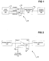
- FIG. 1 shows a representative system 100, according to an embodiment of the invention.
- the system 100 includes a host device 102, an electronic device 104 coupled to a power source 106, and a connection 108 coupling the host device 102 to the electronic device 104.
- the connection 108 is depicted in FIG. 1 as including a conductor 110 (such as a power conductor), a ground conductor 112, and two signal conductors 114A and 114B.
- the connection 108 may be a Universal Serial Bus (USB) connection, or another type of connection.
- the connection 108 may be implemented as a cable in one embodiment.
- USB Universal Serial Bus
- the conductor 110 has a voltage thereon when the host device 102 is operating in a turned-on and fully operational state. That is, when the host device 102 is operating in a turned-on and fully operational state, the host device 102 provides a voltage on the conductor 110.
- the host device 102 may operate in a turned-on and fully operational state when it is not in a sleep state, a hibernation state, or a turned-off state. In the sleep, hibernation, and turned-off states, the host device 102 does not provide a voltage on the conductor 110.
- the host device 102 may be a desktop or laptop computer, or another type of computing or host device.
- the host device 102 In the turned-off state, the host device 102, where it is a computer, is turned off, such that when the device 102 is turned back on, it reboots to begin a new computing session.
- the host device 102 In the hibernation state, the host device 102, where it is a computer, first saves its current state, such as system information, open applications, files, and so on, to a persistent storage like a hard disk drive before turning itself off. When the host device 102 is then turned back on, it reloads its previous state from the persistent storage, so that the previously saved computing session continues. Therefore, the hibernation state may be considered a special type of the turned-off state.
- the host device 102 may enter a low-power mode, in which the device 102 retains power to its volatile memory to maintain its current state, but turns off many other peripherals, such as hard disk drives, monitors, and so on, to consume less power.
- the host device 102 In the turned-on and fully operational state, the host device 102, where it is a computer, is able to be actively used by the user.
- Both the sleep state and the turned-on and fully operational states are different types of turned-on states. The difference is that in the sleep state, power is provided usually just to the volatile memory of the host device 102, such as dynamic random-access memory (DRAM), and perhaps to some other components of the device 102. By comparison, in the turned-on and fully operational state, power is usually provided to all components and peripherals of the device 102.
- DRAM dynamic random-access memory
- connection 108 includes at least the conductor 110.
- the connection 108 may also include the ground conductor 112 to provide a power loop between the host device 102 and the electronic device 104.
- the connection 108 is generally intended to allow the electronic device 104 and the host device 102 to communicate with one another over the connection 108.
- the connection 108 may also include one or more separate signal conductors 114, where in FIG. 1 two signal conductors 114A and 114B are depicted in accordance with the connection 108 being a USB-type connection.
- the electronic device 104 is an image-forming device, such as an inkjet-printing or a laser-printing device
- the device 104 receives the image to be formed onto media thereby from the host device 102 over the connection 108, and more specifically over the signal conductors 114 thereof in one embodiment.
- the electronic device 104 may be another type of peripheral device other than an image-forming device.
- the electronic device 104 receives power to perform its intended functionality, such as image formation on media, from the power source 106.
- the electronic device 104 has a power supply 116 that is coupled to the power source 106, where the power supply 116 converts or otherwise processes the power provided by the power source 106 so that the power is in a usable form for use by other components of the electronic device 104.
- the power source 106 may be an alternating current (AC) power source, such as a wall outlet, into which the power supply 116 is plugged.
- the power source 106 may also be a direct current (DC) power source, such as a battery.
- the power supply 116 is depicted in FIG. 1 as being internal to the electronic device 104, it may also be external to the device 104.
- the power source 106 is depicted in FIG. 1 as being external to the electronic device 104, it may also be internal to the device 104.
- the power supply 116 of the electronic device 104 is connected to the power source 106.
- the electronic device 104 is able to function and operate normally, because it receives power from the power source 106 via the power supply 116.
- the host device 102 when the host device 102 is operating in a turned-on and fully operational state, it provides a voltage on the conductor 110, and this presence of the voltage on the conductor 110 causes the power supply 116 of the electronic device 104 to be connected to the power source 106.
- the power supply 116 of the electronic device 104 is disconnected from the power source 106.
- the electronic device 104 enters a turned-off state as well, in which the device 104 consumes no power. That is, when the host device 102 is not operating in a turned-on and fully operational state, it does not provide a voltage on the conductor 110, and this absence of the voltage on the conductor 110 causes the power supply 116 of the electronic device 104 to be disconnected from the power source 106.
- Power savings are afforded in the system 100 of FIG. 1 due to the electronic device 104 not consuming any power when the voltage is not present on the conductor 110 of the connection 108.
- the electronic device 104 does not have to even consume a small amount of power from the power source 106 so that it is able to turn itself back on at a later point in time, because the voltage on the conductor 110 of the connection 108 instead provides this minimal amount of power.
- electronic device 104 may enter this turned-off state without the use, for instance, of complicated circuitry. This is because whether the electronic device 104 is in a turned-on and fully operational state or in a turned-off state is basically controlled by the presence or absence of the voltage on the conductor 110.
- FIG. 2 shows a power-switching mechanism 200 for the electronic device 104, according to an embodiment of the invention.
- the power-switching mechanism 200 includes a relay 202 and a control input line 204.
- the relay 202 is more generally a switching device, such as a switch, a semiconductor switching device, and so on. That is, whereas the relay 202 is described and depicted in FIG. 2 as particular to one embodiment of the invention, in other embodiments of the invention, other types of switching devices may be employed. Furthermore, the term relay is used herein inclusively as a switching device, to encompass other types of switching devices in addition to the electrical component commonly referred to as a relay.
- the relay 202 is connected between the power supply 116 of the electronic device 104, and the power source 106.
- the relay 202 itself includes a switch 206 and an actuation element 208, as can be appreciated by those of ordinary skill within the art.
- the actuation element 208 may be a coil that when energized due to current running therethrough causes the switch 206 to close.
- the relay 202 is thus a normally open relay, including a normally open switch 206, in one embodiment of the invention.
- the switch 206 has one terminal connected to the power supply 116, and another terminal connected to the power source 106.
- the control input line 204 is connected to the conductor 110 of the connection 108 between the host device 102 and the electronic device 104.
- the actuation element 208 is energized, as one terminal of the actuation element 208 is connected to the control input line 204, and the other terminal of the element 208 is connected to ground 210. Energizing the actuation element 208 causes the switch 206 to close, connecting the power supply 116 to the power source 106.
- a bias network may be included between the control input line 204 and the relay 202, to limit current from the conductor 110 to the relay 202.
- a bias network may include a resistor, for example.
- the power-switching mechanism 200 serves to connect the power source 106 to the power supply 116 of the electronic device 104 when the host device 102 is in a state such that it provides a voltage on the conductor 110, to which the control input line 204 is connected.
- the mechanism 200 disconnects the power source 106 from the power supply 116 of the electronic device 104.
- the electronic device 104 consumes no power when a voltage is absent on the conductor 110.
- the relay 202 is powered by the voltage on the conductor 110, such that the power supply 116 can be completely turned off and disconnected from the power source 106, because the host device 102 will provide the voltage on the conductor 110 for the supply 116 to again be connected to the source 106.
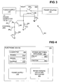
- FIG. 3 shows the power-switching mechanism 200 in more detail than but consistent with the mechanism 200 of FIG. 2, according to another embodiment of the invention.
- a switch 302 and an override line 304 have been added to the power-switching mechanism 200.
- resistors 306 and 308 are depicted in FIG. 2 for the specific implementation or embodiment where a bipolar junction transistor (BJT) is used as the switch 302, as shown in FIG. 2, and as can be appreciated by those of ordinary skill within the art.
- BJT bipolar junction transistor
- Each of the resistors 306 and 308 terminate to ground 210 as shown in FIG. 2.
- the control input line 204 is connected directly to a terminal of the actuation element 208 of the relay 202
- the switch 302 is connected between the line 204 and the actuation element 208.
- a resistor may also be placed in series between the switch 302 and the connection point of the relay 202 and the resistor 308.
- the switch 302 When the override line 304 is high, the switch 302 is on, and the control input line 204, being connected to the conductor 110, controls energizing of the actuation element 208 of the relay 202, and thus is able to control the relay 202 and whether the power supply 116 is connected to the power source 106. Therefore, when the override line 304 is high, the power-switching mechanism 200 of FIG. 3 operates in the same way as the power-switching mechanism 200 of FIG. 2. However, when the override line 304 is low, the switch 302 is off.
- control input line 204 does not control energizing of the actuation element 208 of the relay 202, and the relay 202 remains off regardless of the voltage on the conductor 110 to which the control input line 204 is connected. Therefore, when the switch 302 is off, due to the override line 304 being low, the electronic device 104 remains in the turned-off state, and consumes no power, regardless of whether a voltage is present on the conductor 110.
- the switch 302 may be turned on and off by user control.
- the override line 304 may go high or low based on the state of actuation of an externally accessible physical switch on the electronic device 104.
- the default state of the override line 304 may be high, allowing the conductor 110 via the control input line 204 to control the relay 202, and whether or not the power supply 116 is connected to the power source 106.
- the user may be able to actuate the externally accessible physical switch on the electronic device 104 to cause the override line 304 to go low, causing the power supply 116 to become disconnected from the power source 106 regardless of the voltage present on the conductor 110. This may be desirable to allow the user to turn off the electronic device 104 even when the host device 102 is in a state in which it is providing a voltage on the conductor 110.
- the user is able to override control of the relay 202 by the control input line 204 via the voltage present on the conductor 110, to disconnect the power supply 116 from the power source 106.
- the switch 302 in this embodiment is thus effectively turned on and off by user control, such that the user is able to control whether the electronic device 104 is on when the host device 102 is on.
- the user remains unable to control whether the electronic device 104 is on when the host device 102 is off, such that the device 104 remains off when the device 102 is off regardless of whether the switch 302 has been turned on or off.
- Such inability to turn on the electronic device 104 when the host device 102 is off is due to no voltage being present on the conductor 110 when the device 102 is off. Therefore, even if the switch 302 is on, there is no voltage on the conductor 110 and thus on the control input line 204 to energize the actuation element 208 of the relay 202. The user is thus able to manually override connection of the power supply 116 to the power source 106 by the voltage on the conductor 110, but is unable to manually override disconnection of the supply 116 from the source 106.
- FIG. 4 shows a block diagram of the electronic device 104, according to an embodiment of the invention.
- the electronic device includes a connector 402, the power-switching mechanism 200, a power supply 116, and an image-forming (or other) mechanism 404.
- the mechanism 404 is an image-forming mechanism
- the electronic device 104 is an image-forming device.
- the image-forming mechanism 404 may be an inkjet-printing mechanism or a laser-printing mechanism, such that the electronic device 104 is an inkjet-printing device, such as an inkjet printer, or a laser-printing device, such as a laser printer.
- the mechanism 404 generally includes those components to perform the intended functionality of the electronic device 104.
- the image-forming mechanism 404 includes image-forming components to perform the image-forming functionality of the electronic device 104.
- the intended functionality of the electronic device 104 is other than image formation, the mechanism 404 includes those components to perform such other functionality.
- the connector 402 includes the conductor 110, and may also include the ground conductor 112 and the signal conductors 114.
- the connector 402 is receptive to the connection 108 coupling the host device 102 to the electronic device 104.
- the connection 108 is a Universal Serial Bus (USB) cable terminating in a USB plug
- the connector 402 may be a USB receptacle into which the USB cable can be inserted.
- the connector 402 is capable of connecting the electronic device 104 to the host device 102, such that the device 104 communicates with the device 102 through the connector 402.
- the conductor 110 has a voltage present when the host device 102 is in a state other than a sleep state, a hibernation state, or a turned-off state.
- the power-switching mechanism 200 includes the relay 202, and may also include the switch 302.
- the power supply 116 provides power to the image-forming (or other) mechanism 404, from the power source 106, and is connected to the power source 106 through the relay 202 of the power-switching mechanism 200, as has been described, where the relay 202 is controlled by the voltage on the conductor 110, and optionally via the switch 302.
- the relay 202 connects the power supply 116 to the power source 106 when the voltage is present on the conductor 110, and where the switch 302 is either not present or is present and on.
- FIG. 5 shows a method 500 for using the power-switching mechanism 200, as part of the electronic device 104, and in conjunction with the host device 102, according to an embodiment of the invention.
- the power-switching mechanism 200 as described in relation to FIG. 5 is that of FIG. 2, and not that of FIG. 3. That is, the method 500 is described in relation to the power-switching mechanism 200 not including the switch 302 and the override line 304, for descriptive clarity, as can be appreciated by those of ordinary skill within the art.
- the host device 102 enters, or begins at, a sleep state, a hibernation state, or a turned-off state (502). In response to the host device 102 entering one of these states, the device 102 no longer provides a voltage on the conductor 110, such as a power conductor in one embodiment of the invention, of the connection 108 between the device 102 and the electronic device 104 (504). In response to the absence of a voltage on the conductor 110, the power supply 116 of the electronic device 104 is disconnected from the power source 106 (506).
- a voltage on the conductor 110 such as a power conductor in one embodiment of the invention
- the voltage on the conductor 110 may control the relay 202 of the power-switching mechanism 200 coupling the power supply 116 to the power source 106, such that the absence of the voltage turns off the relay 202, disconnecting the supply 116 from the source 106.
- the host device 102 enters a turned-on and fully operational state (508).
- the device 102 provides a voltage on the conductor 110, such as a power conductor in one embodiment of the invention (510).
- the power supply 116 of the electronic device 104 is connected to the power source 106 (512).
- the voltage on the conductor 110 may control the relay 202 coupling the power supply 116 to the power source 106, such that the presence of the voltage turns on the relay 202, connecting the supply 116 to the source 106.
- the method 500 may repeat at 502, as indicated by the line 514. Furthermore, the method 500 may begin at 508, instead of at 502.
Landscapes
- Engineering & Computer Science (AREA)
- Theoretical Computer Science (AREA)
- Physics & Mathematics (AREA)
- General Physics & Mathematics (AREA)
- General Engineering & Computer Science (AREA)
- Power Sources (AREA)
- Direct Current Feeding And Distribution (AREA)
- Dc-Dc Converters (AREA)
Abstract
Description
Furthermore, whereas in FIG. 2 the
Claims (9)
- A power-switching mechanism (200) for an electronic device (104) comprising:a control input (204) connectable to a conductor (110) of a connection (108) between the electronic device and a host device; and,a switching device (202) capable of coupling a power source (106) to a power supply (116), the switching device controlled by the control input such that the switching device connects the power source to the power supply when a voltage is present on the conductor and the switching device disconnects the power supply from the power source when the voltage is absent on the conductor.
- The power-switching mechanism of claim 1, wherein the electronic device consumes no power when the voltage is absent on the conductor and the switching device correspondingly disconnects the power supply of the electronic device from the power source.
- The power-switching mechanism of claim 1, wherein the conductor has the voltage present when the host device is in a turned-on and fully operational state.
- The power-switching mechanism of claim 1, further comprising a switch (302) coupled between the control input and the switching device, such that when the switch is on, the control input is able to control the switching device via the voltage present on the conductor, and when the switch is off, the switching device disconnects the power supply from the power source and the control input is unable to control the switching device, regardless of the voltage present on the conductor.
- The power-switching mechanism of claim 4, wherein the switch is turned on and off by user control, such that the user is able to override control of the switching device by the control input via the voltage present on the conductor for disconnecting the power supply from the power source.
- The power-switching mechanism of claim 4, wherein the switch is turned on and off by user control, such that the user is able to control whether the electronic device is on when the host device is on but is unable to control whether the electronic device is on when the host device is off, the electronic device remaining off when the host device is off regardless of user control of the switch.
- The power-switching mechanism of claim 1, wherein the connection between the electronic device and the host device is a cable including the conductor, a ground conductor, and at least one signal conductor over which the electronic device and the host device communicate.
- The power-switching mechanism of claim 1, wherein the electronic device is an image-forming device, such that the image-forming device is to receive an image to be formed on media from the host device over the connection.
- A power-switching mechanism (200) for an electronic device (104) comprising:a control input line (204) connectable to a power conductor (110) of a connection (108) between the electronic device and a host device over which the electronic device and the host device communicate, the power conductor having a voltage present when the host device is in a state other than one of: a sleep state, a hibernation state, and a turned-off state; and,a relay (202) capable of coupling a power source (106) to a power supply (116) of the electronic device, the relay controlled by the control input line such that the relay connects the power source to the power supply when the voltage is present on the power conductor and the relay disconnects the power supply from the power source when the voltage is absent on the power conductor.
Applications Claiming Priority (2)
| Application Number | Priority Date | Filing Date | Title |
|---|---|---|---|
| US719174 | 1985-04-03 | ||
| US10/719,174 US6987334B2 (en) | 2003-11-22 | 2003-11-22 | Power-switching mechanism for electronic device |
Publications (2)
| Publication Number | Publication Date |
|---|---|
| EP1533662A2 true EP1533662A2 (en) | 2005-05-25 |
| EP1533662A3 EP1533662A3 (en) | 2006-12-27 |
Family
ID=34435801
Family Applications (1)
| Application Number | Title | Priority Date | Filing Date |
|---|---|---|---|
| EP20040257124 Withdrawn EP1533662A3 (en) | 2003-11-22 | 2004-11-17 | Power-switching mechanism for electronic device |
Country Status (3)
| Country | Link |
|---|---|
| US (1) | US6987334B2 (en) |
| EP (1) | EP1533662A3 (en) |
| JP (1) | JP3931186B2 (en) |
Families Citing this family (8)
| Publication number | Priority date | Publication date | Assignee | Title |
|---|---|---|---|---|
| US20030212130A1 (en) * | 2000-09-14 | 2003-11-13 | Miller Donald W. | Creatine ester anti-inflammatory compounds and formulations |
| US20070180277A1 (en) * | 2006-01-27 | 2007-08-02 | Subramanian Jayaram | Enhanced printer power management |
| US7644295B1 (en) * | 2006-06-26 | 2010-01-05 | Rockwell Automation Technologies, Inc. | Powering a human machine interface by way of USB |
| US7598631B2 (en) * | 2007-01-29 | 2009-10-06 | Fifth Light Technology Ltd. | Addressable power switch |
| TWI391823B (en) * | 2009-09-14 | 2013-04-01 | Avision Inc | Peripheral device capable of connecting with a computer host and power control method thereof |
| US20110095728A1 (en) | 2009-10-28 | 2011-04-28 | Superior Communications, Inc. | Method and apparatus for recharging batteries in a more efficient manner |
| TWI428750B (en) * | 2010-12-30 | 2014-03-01 | Via Tech Inc | Processing device and operation system utilizing the same |
| CN109378733B (en) * | 2018-12-04 | 2024-10-22 | 广州南沙珠江啤酒有限公司 | Junction box suitable for ink jet numbering machine |
Family Cites Families (13)
| Publication number | Priority date | Publication date | Assignee | Title |
|---|---|---|---|---|
| JPS5331952A (en) | 1976-09-06 | 1978-03-25 | Hitachi Ltd | Solid switch circuit |
| US4581571A (en) | 1984-03-02 | 1986-04-08 | Eaton Corporation | Electrical power disconnect system |
| US4670810A (en) | 1986-03-17 | 1987-06-02 | Electronic Instrument & Specialty Corp. | Zero-current a.c. switching system |
| US4820938A (en) | 1988-06-03 | 1989-04-11 | The Watt Watcher, Inc. | Low voltage motion sensor for activating a high voltage load |
| US5003578A (en) | 1989-08-11 | 1991-03-26 | Lin Den K | Power-saving device for a cable-information receiving/transmitting apparatus |
| JP3100249B2 (en) * | 1992-12-03 | 2000-10-16 | キヤノン株式会社 | Image forming apparatus and method of controlling image forming apparatus |
| US5491721A (en) | 1994-02-23 | 1996-02-13 | Motorola, Inc. | Modem powering method and apparatus |
| KR970073986A (en) * | 1996-05-15 | 1997-12-10 | 김광호 | Printer power control device and method |
| JP2000092754A (en) | 1998-09-14 | 2000-03-31 | Toshiba Corp | Power supply circuit for electrical equipment |
| US6282451B1 (en) | 1998-11-24 | 2001-08-28 | Lawrence D. White | Method and apparatus for allowing or disrupting passage of power in electrical appliances |
| JP2003118204A (en) * | 2001-10-16 | 2003-04-23 | Ricoh Co Ltd | Printing equipment |
| KR100460951B1 (en) * | 2002-01-28 | 2004-12-09 | 삼성전자주식회사 | Printer capable of controlling power supply by a host |
| TW561334B (en) * | 2002-06-20 | 2003-11-11 | Benq Corp | Power management system of liquid crystal display |
-
2003
- 2003-11-22 US US10/719,174 patent/US6987334B2/en not_active Expired - Fee Related
-
2004
- 2004-11-16 JP JP2004331791A patent/JP3931186B2/en not_active Expired - Fee Related
- 2004-11-17 EP EP20040257124 patent/EP1533662A3/en not_active Withdrawn
Also Published As
| Publication number | Publication date |
|---|---|
| JP2005160295A (en) | 2005-06-16 |
| US20050110350A1 (en) | 2005-05-26 |
| US6987334B2 (en) | 2006-01-17 |
| EP1533662A3 (en) | 2006-12-27 |
| JP3931186B2 (en) | 2007-06-13 |
Similar Documents
| Publication | Publication Date | Title |
|---|---|---|
| CN105630724B (en) | A kind of USB Type C system control circuits | |
| US7454641B2 (en) | System powered from a local area network cable | |
| CN100373367C (en) | Apparatus and method for controlling pin voltage of connector | |
| US6091617A (en) | Automatic power supply selector for ACPI-compliant PCI devices | |
| US6128743A (en) | Intelligent system and method for universal bus communication and power | |
| EP1451668B1 (en) | Sensing socket assembly | |
| US10203707B2 (en) | Power sharing solid-state relay | |
| US20090082910A1 (en) | Information processing apparatus | |
| CN101165990B (en) | Power supply management system, terminal, information processor and power supply management law | |
| US20030110403A1 (en) | System for shared power supply in computer peripheral devices | |
| US8055831B2 (en) | Computer system for supplying electric power to external apparatus and control method thereof | |
| CN1245931A (en) | Method for waking up signal control computer system power supply by using local area network and its equipment | |
| US7062191B2 (en) | Image forming device including AC loads driven by an AC power supply | |
| CN110649694A (en) | NCSI network card power supply system | |
| US20020111076A1 (en) | Data-interface-controlled multiple plug | |
| US9195297B2 (en) | Bridging device for connecting to a host executes a power saving operation or a polling operation according to status detected by the connection detector | |
| US6987334B2 (en) | Power-switching mechanism for electronic device | |
| US20140013135A1 (en) | System and method of controlling a power supply | |
| KR20090060431A (en) | Reduced oscillation in systems with foldback current limit when inductive loads are connected | |
| US6351820B1 (en) | PC card with automated drag and sleep function | |
| CN101441505B (en) | Energy-saving controlled computer power supply device | |
| CN110994973B (en) | A power supply and server | |
| WO2024067031A1 (en) | Power switching circuit and electronic device | |
| US20220155837A1 (en) | Power Management Control Method in Use of Connector | |
| CN116248417A (en) | Ethernet power supply and its power saving control method |
Legal Events
| Date | Code | Title | Description |
|---|---|---|---|
| PUAI | Public reference made under article 153(3) epc to a published international application that has entered the european phase |
Free format text: ORIGINAL CODE: 0009012 |
|
| AK | Designated contracting states |
Kind code of ref document: A2 Designated state(s): AT BE BG CH CY CZ DE DK EE ES FI FR GB GR HU IE IS IT LI LU MC NL PL PT RO SE SI SK TR |
|
| AX | Request for extension of the european patent |
Extension state: AL HR LT LV MK YU |
|
| PUAL | Search report despatched |
Free format text: ORIGINAL CODE: 0009013 |
|
| AK | Designated contracting states |
Kind code of ref document: A3 Designated state(s): AT BE BG CH CY CZ DE DK EE ES FI FR GB GR HU IE IS IT LI LU MC NL PL PT RO SE SI SK TR |
|
| AX | Request for extension of the european patent |
Extension state: AL HR LT LV MK YU |
|
| RIC1 | Information provided on ipc code assigned before grant |
Ipc: G06F 1/26 20060101ALI20061123BHEP Ipc: B41J 29/393 20060101ALI20061123BHEP Ipc: G03G 15/00 20060101AFI20050303BHEP |
|
| 17P | Request for examination filed |
Effective date: 20070507 |
|
| AKX | Designation fees paid |
Designated state(s): DE ES FR GB |
|
| STAA | Information on the status of an ep patent application or granted ep patent |
Free format text: STATUS: THE APPLICATION IS DEEMED TO BE WITHDRAWN |
|
| 18D | Application deemed to be withdrawn |
Effective date: 20090603 |