EP1533623A2 - Method of detecting a branch with an earth fault - Google Patents
Method of detecting a branch with an earth fault Download PDFInfo
- Publication number
- EP1533623A2 EP1533623A2 EP05100754A EP05100754A EP1533623A2 EP 1533623 A2 EP1533623 A2 EP 1533623A2 EP 05100754 A EP05100754 A EP 05100754A EP 05100754 A EP05100754 A EP 05100754A EP 1533623 A2 EP1533623 A2 EP 1533623A2
- Authority
- EP
- European Patent Office
- Prior art keywords
- branch
- difference
- zero
- ground fault
- admittance
- Prior art date
- Legal status (The legal status is an assumption and is not a legal conclusion. Google has not performed a legal analysis and makes no representation as to the accuracy of the status listed.)
- Withdrawn
Links
Images


Classifications
-
- H—ELECTRICITY
- H02—GENERATION; CONVERSION OR DISTRIBUTION OF ELECTRIC POWER
- H02H—EMERGENCY PROTECTIVE CIRCUIT ARRANGEMENTS
- H02H7/00—Emergency protective circuit arrangements specially adapted for specific types of electric machines or apparatus or for sectionalised protection of cable or line systems, and effecting automatic switching in the event of an undesired change from normal working conditions
- H02H7/26—Sectionalised protection of cable or line systems, e.g. for disconnecting a section on which a short-circuit, earth fault, or arc discharge has occured
-
- G—PHYSICS
- G01—MEASURING; TESTING
- G01R—MEASURING ELECTRIC VARIABLES; MEASURING MAGNETIC VARIABLES
- G01R31/00—Arrangements for testing electric properties; Arrangements for locating electric faults; Arrangements for electrical testing characterised by what is being tested not provided for elsewhere
- G01R31/50—Testing of electric apparatus, lines, cables or components for short-circuits, continuity, leakage current or incorrect line connections
- G01R31/52—Testing for short-circuits, leakage current or ground faults
-
- G—PHYSICS
- G01—MEASURING; TESTING
- G01R—MEASURING ELECTRIC VARIABLES; MEASURING MAGNETIC VARIABLES
- G01R31/00—Arrangements for testing electric properties; Arrangements for locating electric faults; Arrangements for electrical testing characterised by what is being tested not provided for elsewhere
- G01R31/08—Locating faults in cables, transmission lines, or networks
- G01R31/081—Locating faults in cables, transmission lines, or networks according to type of conductors
- G01R31/086—Locating faults in cables, transmission lines, or networks according to type of conductors in power transmission or distribution networks, i.e. with interconnected conductors
-
- G—PHYSICS
- G01—MEASURING; TESTING
- G01R—MEASURING ELECTRIC VARIABLES; MEASURING MAGNETIC VARIABLES
- G01R31/00—Arrangements for testing electric properties; Arrangements for locating electric faults; Arrangements for electrical testing characterised by what is being tested not provided for elsewhere
- G01R31/08—Locating faults in cables, transmission lines, or networks
- G01R31/088—Aspects of digital computing
-
- H—ELECTRICITY
- H02—GENERATION; CONVERSION OR DISTRIBUTION OF ELECTRIC POWER
- H02H—EMERGENCY PROTECTIVE CIRCUIT ARRANGEMENTS
- H02H3/00—Emergency protective circuit arrangements for automatic disconnection directly responsive to an undesired change from normal electric working condition with or without subsequent reconnection ; integrated protection
- H02H3/38—Emergency protective circuit arrangements for automatic disconnection directly responsive to an undesired change from normal electric working condition with or without subsequent reconnection ; integrated protection responsive to both voltage and current; responsive to phase angle between voltage and current
- H02H3/385—Emergency protective circuit arrangements for automatic disconnection directly responsive to an undesired change from normal electric working condition with or without subsequent reconnection ; integrated protection responsive to both voltage and current; responsive to phase angle between voltage and current using at least one homopolar quantity
Definitions
- the present invention relates to a method and an apparatus for determination a faulty branch in an inductive star point compensated electrical power supply network, wherein at least the displacement voltage as measured variables or the sum of the phase ground voltages of the individual phases and the zero currents all branches or the sum of the individual phase currents of these branches or equivalent measured variables are selected and measured.
- measured variables which are evaluated by the methods, at least the star point ground voltage or the sum of the phase ground voltages of the individual phases and the zero currents or the sum of the individual phase currents of all branches or equivalent measured variables of particular advantage, since these measures for a plurality can be used by different line models or evaluation methods.
- a simple method for determining the defectiveness of the overall network results, if the real parts of the difference zero admittance Y (i) of all branches are determined and a Erd gleichvermutung remains intact, as long as the sum of the real parts of the Differenznulladmittanzen is negative across all branches.
- a branch of a size which is made up of the difference of the real part of the difference zero admittance for the power-frequency fundamental wave and a threshold, which is, for example, by the sum g r of the real parts of the difference zero admittances over those branches whose real part of the difference zero admittance is positive, possibly including the iron and / or copper losses of the quenching coil, formed and determines a degree of fulfillment for the existence of a ground fault.
- a distance function normalized to the threshold value is advantageously used, which represents the distance between the real part and the threshold value, from which the degree of fulfillment for the presence of a ground fault is then determined.
- a monitored branch or line section After adjusting a quench coil or a different kind of neutral earth impedance change, for example, to minimize the fault current at the ground fault point, for a monitored branch or line section advantageously a difference zero impedance after impedance change as a quotient of the difference from the branch zero current associated with the branch after changing the Neutral point earth fault in the earth fault case and the branch zero current before earth fault occurrence and the difference of the residual voltage after changing the neutral point earth impedance in case of earth fault and before ground fault occurrence, which can also be evaluated to detect earth faults.
- an admittance difference is advantageously determined as the difference between the difference zero admittance before and the difference zero admittance after changing the star point earth impedance, from which a degree of fulfillment for the presence of a ground fault in a branch can be determined.
- the degree of fulfillment for the presence of a ground fault can be determined, for example, from the relative absolute values of the admittance differences for this branch with respect to the power-frequency fundamental wave, for example based on the sum of the amounts of the admittance differences.
- the application of this method results from the knowledge that changes in the detuning of the entire network erased, eg by an adjustment of the core coil, the fault current at the ground fault point and thus the Differenznulladmittanz before and after a change in the neutral earth impedance, while the Differenznulladmittanz fault-free branches remains unchanged before and after a change in the neutral point earth impedance.
- the degrees of fulfillment determined by the two methods are optionally linked to a total degree of completion and subsequently a ground fault for a branch if this total degree of completion is indicated by a two or more-valued logic, eg with methods of Fuzzy Logic exceeds a certain value.
- the existence of the prerequisites for the application of the respective method can be included, which is advantageously taken into account in the form of a degree of fulfillment for the existence of the prerequisites for the application of this particular method.
- the logic operation is realized by using a two or more-valued logic, for example by Fuzzy Logic.
- a particularly sharp statement about the overall degree of completion for the existence of a Earth leakage at a particular branch can be due to formation of the algebraic product the degree of fulfillment for the presence above a predetermined threshold value of a ground fault via the individual methods.
- a comparatively softer statement about the overall degree of completion for the presence of a ground fault a certain branch can be graded by the algebraic mean with the degrees of process fulness weighted degrees of fulfillment for the existence of an earth fault of the individual Methods are determined.
- the evaluation unit comprises a processing unit for measuring and evaluation of the measured variables, wherein the evaluation unit to set up is, by determining and evaluating a difference zero admittance as a quotient of the Difference from the Abzweigullstrom assigned to the branch or line section after ground fault entry and the branch zero current before ground fault entry and the difference the displacement voltage after and before the Erd gleicheintritt for each branch one Degree of fulfillment for the existence of a ground fault.
- the degrees of fulfillment Two different evaluation methods are advantageous in a linking unit Logically linked to a total degree of completion.
- the supply network 1 shown in Figure 1 has a three-phase busbar 2, which is fed by a transformer 3, the star point via an extinguishing choke 4, for example, a Tauchkernspule whose inductance is generally tuned to the resonance point of the displacement voltage U ne , grounded, So an erased or inductively star point compensated supply network.
- an extinguishing choke 4 for example, a Tauchkernspule whose inductance is generally tuned to the resonance point of the displacement voltage U ne , grounded, So an erased or inductively star point compensated supply network.
- 2 or more branches 1, 2,... N are connected to the busbar, each having ohmic and capacitive derivatives C, as well as series resistances and inductances.
- a ground fault with the ohmic conductance g k is indicated at location x, via which the fault current I F flows.
- FIG. 2 shows in more detail the line model on which the calculations are based.
- a suitable model (equivalent circuit diagram) to design the line.
- the structure of the model depends heavily on the considered one Frequency spectrum. Basically, one line is in the entire frequency spectrum only writable by a system with distributed parameters.
- the methods described below are used, on the one hand, to determine the degree of erosion Branching (earth fault of a phase) and provides on the other hand statements about the presence of a ground fault in the deleted overall network.
- the methods described set as measured variables, the three phase ground voltages U 1e , U 2e , U 3e , or the neutral point ground voltage (or displacement voltage) U ne and the measurement of the zero currents of all branches (I 01 , I 02 , ..., I on ) or as a replacement for a A unitedeegullstrom the sum of the phase currents i 1 , i 2 , i 3 this branch ahead, possibly in a slightly modified form, for example, the sampling and digitization of a measured variable at equidistant time intervals, the measurement of the mains frequency fundamental component and / or a or several harmonic components of these measured quantities in magnitude and phase with respect to a (temporal) reference variable.
- the star point ground voltage or displacement voltage U ne alternatively, the arithmetic mean of the three phase ground voltages ((D 1e + U 2e + U 3e ) / 3) can be used.
- the fundamental - and odd-numbered Obwellenanteile all measured variables - using a discrete Fourier transform over a integer multiple of the period of the fundamental wave performed.
- the used Sampling frequency for measured value sampling and subsequent analog / digital conversion should ideally also an integer multiple of the fundamental frequency and the O-wave frequencies be in the kilohertz range.
- the arithmetic operations are also complex, as long as they are complex quantities perform.
- Wattmetric summation admittance method This method considers only the fundamental components (50 Hz, 60 Hz) of the measured quantities and presupposes the settled (stationary) system state.
- the determination of the faulty branch is made by determining the difference zero admittances as a quotient of zero current and voltage differences with subsequent verification of their real parts.
- the derivation shows that the real parts of the difference zero admittances of faultless branches or line sections are positive, while the real parts of the difference zero admittances of faulty branches or line sections assume a negative value determined by g s from equation (7).
- the further execution of the method yields a standardized degree of fulfillment, lying between 0 and 1, of the ground fault presumption p (1, n) for all N branches with n equal to 1 to N.
- Zero admittance method with coil detuning or change of the star point ground impedance The method is based on the fact that the difference zero adders with respect to the line frequency fundamental components described in the wattmetric sum admittance method undergo a change before and after an adjustment of the core coil or a change of the star point earth impedance in faulty branches while in healthy branches they are not influenced by the coil adjustment or by the change of the neutral point earth impedance.
- the method presupposes a stable (stationary) system state. As a result, the execution of the method yields a normalized degree of fulfillment of the ground fault presumption p (2, n) between 0 and 1 for all N branches with n equal to 1 to N.
- each of the methods described above is subject to its significance Procedural requirements. Only if these conditions are met can that be Process result (determination of the faulty branch) considered meaningful become. Otherwise, the result is to be rejected.
- the height of the neutral point ground voltage (residual voltage) U ne after ground fault entry is a measure of the low resistance of the ground fault.
- the absolute amount of the relative displacement voltage U ne after earth leakage, based on the rated voltage of the grid can be used as the satisfaction measure pv (1) of the process requirements. This measure should be set to zero if the ground fault was only transient.
- the phase voltage normalized displacement voltage U ne after ground fault entry can be defined as a measure of the compliance pv (2) of the process requirements. This measure should be set to zero if the ground fault was only transient.
- the fulfillment measures p (j, n) defined above for the earth fault presumption of the jth Method and n-th branches can in the sense of fuzzy logic as membership functions the linguistic variable "branch n is subject to method representative, Fuzzymenge be construed.
- the decision criteria for determining the faulty branch can be formulated differently. Below are two non-limiting Examples are presented how the decision logic can be realized. The formulation The requirements of the decision logic also depend on that collected in practice Experiences.
- Version 1 Based on the consideration that every method above a certain degree of fulfillment must provide a representative statement about the faulty branch, the logical "rounding" over all those process-specific degrees of fulfillment of the same branch can be performed as total degree of completion of a branch, the degree of fulfillment of the procedural requirements above a threshold P lim . If the algebraic product is used as the T-NORM, then for the branch-specific total degree of filling pg (i) with i equal to 1 to N for branches 1 to N:
- the branch is identified as having the pg (i) of all N branches is largest (maximum).
- FIG. 3 is a block diagram for a non-limiting embodiment for implementation represented the device according to the invention.
- the device comprises a scanning unit 10, with which the analog measured quantities supplied by corresponding known measuring devices and transducers described above can be sampled and subsequently converted into digital values, namely the signals supplied by the branch current transformers for the zero currents i 0 of all branches derived from the Voltage transducers coming signals for the phase ground voltages U 1e , U 2e , U 3e and / or the signal supplied by the voltage measurement winding of the quenching coil (Tauchkernspule) or an additional voltage converter for the neutral point ground voltage U ne (displacement voltage).
- synchronizing unit 11 is provided, which for forming a temporal reference signal as a phase reference for the scanning unit 10 is set up.
- This phase reference is sent to a PLL unit 12 (phase locked loop) delivered, which is used for phase-synchronous multiplication of the network frequency and on the one hand an output signal for sampling the measurement signals to the scanning unit 10, on the other hand an output signal to a DFT unit 14 (digital Fourier transformation) for Fourier Hornberg or for Fourier transformation of the sampled and A / D converted Delivers measured values.
- PLL unit 12 phase locked loop
- DFT unit 14 digital Fourier transformation
- the sampled and A / D converted measured values are first transmitted to a trigger unit 13, in which the measured zero currents i 0 and the displacement voltage U ne , and the phase ground voltages are monitored for sudden changes. Whenever predefined threshold values are exceeded, this trigger unit 13 triggers a measured-value recording cycle provided by the method for one of these measured variables. The recorded measuring cycles are stored in a memory (not shown). Further, the DFT unit 14 is connected to the synchronizing unit 11 via the PLL unit 12 for determining the phase relations of the measured quantities with respect to the reference signal.
- the stored measured values are then counted by a number of evaluation units 16, 18 evaluated by one evaluation method.
- the unit 16 may be implemented the first method described above (sum admittance method) and the unit 18 for carrying out the second method described above (Nulladmittanzmaschinen with change of the neutral point earth impedance).
- Each unit 16, 18 delivers in Case of a triggered recording and evaluation of measured variables, for each branch i a result concerning the degree of fulfillment p (i) for the presence of a ground fault a certain branch and a further result for the degree of fulfillment pv (i) for the Existence of the conditions for the application of the respective procedure.
- a multi-valued one Logic e.g. a fuzzy logic
- a meaningful result total degree of completion pg (i)
- an output unit 20 which e.g. a display, an alarm, an emergency operation, a shutdown od.
Abstract
Description
Die vorliegende Erfindung bezieht sich auf ein Verfahren und eine Vorrichtung zur Bestimmung eines erdschlussbehafteten Abzweiges in einem induktiv sternpunktkompensierten elektrischen Stromversorgungsnetz, wobei als Messgrößen zumindest die Verlagerungsspannung oder die Summe der Phasen-Erdspannungen der einzelnen Phasen und die Nullströme aller Abzweige oder die Summe der einzelnen Phasenströme dieser Abzweige oder gleichwertige Messgrößen ausgewählt und gemessen werden.The present invention relates to a method and an apparatus for determination a faulty branch in an inductive star point compensated electrical power supply network, wherein at least the displacement voltage as measured variables or the sum of the phase ground voltages of the individual phases and the zero currents all branches or the sum of the individual phase currents of these branches or equivalent measured variables are selected and measured.
Zur Bestimmung eines erdschlussbehafteten Abzweiges in einem gelöschten elektrischen Stromversorgungsnetz ist eine Anzahl von unterschiedlichen Verfahren bekannt, die z.B. in der WO92/18872, der EP 82103, der DE 27 11 629 oder der WO96/27138, aber auch in der Fachliteratur, z.B. Schutztechnik in elektrischen Netzen, VDE Verlag, ISBN 3-8007-1498-1, ausführlich beschrieben sind. Jedes dieser Verfahren hat jedoch bestimmte Nachteile, z.B. können mit einigen Verfahren keine kurzzeitigen Erdschlüsse erkannt werden, wogegen bei anderen Verfahren beispielsweise keine hochohmigen Erdschlüsse erkannt werden können.To determine a faulty branch in a deleted electrical Power grid is known a number of different methods, e.g. in WO92 / 18872, EP 82103, DE 27 11 629 or WO96 / 27138, but also in the Technical literature, e.g. Protection technology in electrical networks, VDE Verlag, ISBN 3-8007-1498-1, are described in detail. However, each of these methods has certain disadvantages, e.g. can be detected with some methods no short-term ground faults, whereas at other methods, for example, no high-impedance ground faults can be detected.
Es ist daher eine Aufgabe der vorliegenden Erfindung, ein neuartiges Verfahren zu schaffen, bei welchem die Nachteile bekannter Verfahren vermieden werden und welches sich insbesondere durch eine besonders hohe Verfahrenssicherheit auszeichnet, bei welchem jedoch kein wesentlicher zusätzlicher gerätetechnischer Aufwand entsteht und folglich keine Mehrkosten verursacht werden. Insbesondere ist es ein Ziel der vorliegenden Erfindung, ein Verfahren zu schaffen, welches sich besonders für die Erfassung hochohmiger Erdfehler eignet.It is therefore an object of the present invention to provide a novel method in which the disadvantages of known methods are avoided and which in particular characterized by a particularly high process reliability, in which, however There is no significant additional equipment expense and therefore no additional costs caused. In particular, it is an object of the present invention to provide a method which is particularly suitable for the detection of high-impedance earth faults.
Diese Aufgabe wird durch ein Verfahren gelöst, welches zur Bestimmung eines erdschlussbehafteten
Abzweiges für die Abzweige eine Differenznulladmittanz als Quotient aus der
Differenz aus dem dem Abzweig zugeordneten Abzweignullstrom nach Erdschlusseintritt und
dem Abzweignullstrom vor Erdschlusseintritt und der Differenz der Verlagerungsspannung
nach und vor dem Erdschlusseintritt ermittelt und ausgewertet wird.
Da sowohl der Zähler als auch der Nenner der Differenznulladmittanz aus einer Differenz
kurzzeitig aufeinanderfolgender Messungen besteht, werden Fehler durch Fremdinduktionen
auf den Verdrahtungsleitungen der Messeingänge weitgehend eliminiert. Bedingt durch die
signifikante Erhöhung der Verlagerungsspannung im Erdschlussfall und die relativ kleine
Verlagerungsspannung bei fehlerfreiem Netzbetrieb treten sowohl im Zähler als auch im
Nenner vernünftig große Signaldifferenzen auf. Die in den Abzweignullströmen vorkommenden
Unsymmetrieströme, bedingt durch kapazitive sowie ohmsche Unsymmetrien der drei
Leiter gegen Erde (innere Unsymmetrien) sowie durch kapazitive Einkoppelungen, verursacht
von parallelen Leitungsführungen (äußere Unsymmetrien), werden durch die Differenzbildung
der Nullströme gänzlich eliminiert. Dadurch erhält man ein Verfahren, welches
die Zuverlässigkeit und Verfahrenssicherheit erhöht. Bei dieser Anwendung können besonders
hochohmige Erdschlüsse erkannt und einem bestimmten Abzweig zugeordnet werden.
Als Messgrößen, welche durch die Methoden ausgewertet werden, sind zumindest die
Sternpunkt-Erdspannung oder die Summe der Phasen-Erdspannungen der einzelnen Phasen
und die Nullströme oder die Summe der einzelnen Phasenströme aller Abzweige oder
gleichwertiger Messgrößen von besonderem Vorteil, da diese Messgrößen für eine Mehrzahl
von unterschiedlichen Leitungsmodellen oder Auswertemethoden genutzt werden können.This object is achieved by a method which determines a differential zero admittance as a quotient of the difference between the branch zero flow associated with the branch after Erdschlusseintritt and the Abzweignullstrom before Erdschlusseintritt and the difference of the displacement voltage after and before Erdschlusseintritt to determine a faulty branch for the branches becomes.
Since both the numerator and the denominator of the difference zero admittance consist of a difference of short-term successive measurements, errors due to extraneous inductances on the wiring lines of the measuring inputs are largely eliminated. Due to the significant increase in the residual voltage in the case of an earth fault and the relatively small displacement voltage during faultless mains operation, reasonably large signal differences occur both in the numerator and in the denominator. The unbalance currents occurring in the branch zero currents due to capacitive and ohmic asymmetries of the three conductors to ground (internal asymmetries) as well as capacitive couplings caused by parallel cable runs (external asymmetries) are completely eliminated by subtraction of the zero currents. This gives a method which increases reliability and process safety. In this application, particularly high-impedance ground faults can be detected and assigned to a specific feeder. As measured variables, which are evaluated by the methods, at least the star point ground voltage or the sum of the phase ground voltages of the individual phases and the zero currents or the sum of the individual phase currents of all branches or equivalent measured variables of particular advantage, since these measures for a plurality can be used by different line models or evaluation methods.
Vorteilhafter Weise werden die Differenznulladmittanzen nur bezüglich der netzfrequenten Grundwellenanteile der Messwerte ermittelt, wobei die Grundwellenanteile vorzugsweise mit Hilfe der diskreten Fouriertransformation bzw. durch Fourierreihenentwicklung oder gleichwertige Methoden bestimmt werden.Advantageously, the difference zero admittances only with respect to the mains frequency Fundamental wave components of the measured values determined, the fundamental components preferably with Help of the discrete Fourier transformation or by Fourierreihenentwicklung or equivalent Methods are determined.
Ein einfaches Verfahren zur Ermttlung der Fehlerhaftigkeit des Gesamtnetzes ergibt sich, wenn die Realteile der Differenznulladmittanz Y(i) aller Abzweige ermittelt werden und eine Erdschlussvermutung aufrecht bleibt, solange die Summe der Realteile der Differenznulladmittanzen über alle Abzweige negativ ist.A simple method for determining the defectiveness of the overall network results, if the real parts of the difference zero admittance Y (i) of all branches are determined and a Erdschlussvermutung remains intact, as long as the sum of the real parts of the Differenznulladmittanzen is negative across all branches.
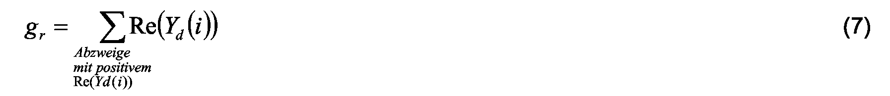
Vorteilhaft wird für einen Abzweig aus einer Größe, welche aus der Differenz des Realteils der Differenznulladmittanz für die netzfrequente Grundwelle und einem Schwellwert, welcher beispielsweise durch die Summe gr der Realteile der Differenznulladmittanzen über jene Abzweige, deren Realteil der Differenznulladmittanz positiv ist, gegebenenfalls unter Einbeziehung der Eisen- und/oder Kupfer verluste der Löschspule, gebildet und daraus ein Erfülltheitsgrad für das Vorliegen eines Erdschlusses ermittelt. Dazu wird vorteilhaft eine auf den Schwellwert normierte Distanzfunktion verwendet, die den Abstand zwischen dem Realteil und dem Schwellwert repräsentiert, aus der dann der Erfülltheitsgrad für das Vorliegen eines Erdfehlers ermittelt wird.Advantageously, for a branch of a size, which is made up of the difference of the real part of the difference zero admittance for the power-frequency fundamental wave and a threshold, which is, for example, by the sum g r of the real parts of the difference zero admittances over those branches whose real part of the difference zero admittance is positive, possibly including the iron and / or copper losses of the quenching coil, formed and determines a degree of fulfillment for the existence of a ground fault. For this purpose, a distance function normalized to the threshold value is advantageously used, which represents the distance between the real part and the threshold value, from which the degree of fulfillment for the presence of a ground fault is then determined.
Um auch die Fehlerhaftigkeit von Ringschaltungen bzw. von einer andersartigen Vermaschung von Abzweigen erfassen zu können, werden im Fall, dass die Realteile der Differenznulladmittanzen mehrerer Abzweige negativ sind, die Summe dieser negativen Realteile für die Ermittlung des Erfülltheitsgrades herangezogen .To the defectiveness of ring circuits or of a different type of meshing of branches, in the case that the real parts of the difference zero admittances become several branches are negative, the sum of these negative real parts for the determination of the degree of fulfillment used.
Nach dem Verstellen einer Löschspule oder einer andersartigen Änderung der Sternpunkt-Erdimpedanz,
zum Beispiel zur Minimierung des Fehlerstromes an der Erdschlussstelle,
kann für einen überwachten Abzweig oder Leitungsabschnitt vorteilhaft eine Differenznulladmittanz
nach Impedanzänderung als Quotient aus der Differenz aus dem dem Abzweig
zugeordneten Abzweignullstrom nach Änderung der Sternpunkt-Erdimpedanz im Erdschlussfall
und dem Abzweignullstrom vor Erdschlusseintritt und der Differenz der Verlagerungsspannung
nach Änderung der Sternpunkt-Erdimpedanz im Erdschlussfall und vor dem Erdschlusseintritt
ermittelt werden, die ebenfalls zur Erfassung von Erdschlüssen ausgewertet
werden kann. Dazu wird vorteilhaft eine Admittanzdifferenz als Differenz aus der Differenznulladmittanz
vor und der Differenznulladmittanz nach Änderung der Sternpunkt-Erdimpedanz
ermittelt, aus der ein Erfülltheitsgrad für das Vorliegen eines Erdfehlers in einem Abzweig
ermittelt werden kann.
Der Erfülltheitsgrad für das Vorliegen eines Erdschlusses kann beispielsweise aus den relativen
Absolutbeträgen der Admittanzdifferenzen für diesen Abzweig bezüglich der netzfrequenten
Grundwelle, z.B. bezogen auf die Summe der Beträge der Admittanzdifferenzen,
ermittelt werden. Die Anwendung dieser Methode resultiert aus der Erkenntnis, dass sich bei
einer Änderung der Verstimmung des gelöschten Gesamtnetzes, z.B. durch eine Verstellung
der Tauchkernspule, der Fehlerstrom an der Erdschlussstelle und damit die Differenznulladmittanz
vor und nach einer Änderung der Sternpunkt-Erdimpedanz ändert, während die Differenznulladmittanz
fehlerfreier Abzweige vor und nach einer Änderung der Sternpunkt-Erdimpedanz
unverändert bleibt.After adjusting a quench coil or a different kind of neutral earth impedance change, for example, to minimize the fault current at the ground fault point, for a monitored branch or line section advantageously a difference zero impedance after impedance change as a quotient of the difference from the branch zero current associated with the branch after changing the Neutral point earth fault in the earth fault case and the branch zero current before earth fault occurrence and the difference of the residual voltage after changing the neutral point earth impedance in case of earth fault and before ground fault occurrence, which can also be evaluated to detect earth faults. For this purpose, an admittance difference is advantageously determined as the difference between the difference zero admittance before and the difference zero admittance after changing the star point earth impedance, from which a degree of fulfillment for the presence of a ground fault in a branch can be determined.
The degree of fulfillment for the presence of a ground fault can be determined, for example, from the relative absolute values of the admittance differences for this branch with respect to the power-frequency fundamental wave, for example based on the sum of the amounts of the admittance differences. The application of this method results from the knowledge that changes in the detuning of the entire network erased, eg by an adjustment of the core coil, the fault current at the ground fault point and thus the Differenznulladmittanz before and after a change in the neutral earth impedance, while the Differenznulladmittanz fault-free branches remains unchanged before and after a change in the neutral point earth impedance.
Um die Zuverlässigkeit der Erkennung zu erhöhen , werden gegebenenfalls für die Abzeige
die mit den beiden Verfahren ermittelten Erfülltheitsgrade durch eine zwei oder mehrwertige
Logik, z.B. mit Methoden der Fuzzy Logic, zu einem Gesamterfülltheitsgrad verknüpft und
nachfolgend für einen Abzweig ein Erdschluss angezeigt, wenn dieser Gesamterfülltheitsgrad
einen bestimmten Wert überschreitet. Dazu kann auch das Vorliegen der Voraussetzungen
für die Anwendung der jeweiligen Methode einbezogen werden, was vorteilhafter
Weise in Form eines Erfülltheitsgrades für das Vorliegen der Voraussetzungen zur Anwendung
dieser jeweiligen Methode berücksichtigt wird.
Durch diese logische Verknüpfung zumindest zweier unterschiedlicher Verfahren kann ein
größerer Anwendungsbereich und über diesen Anwendungsbereich eine größere Verfahrenssicherheit
realisiert werden, wobei die zwei Verfahren durch eine einzelne Einrichtung
realisiert werden können, da im wesentlichen von denselben Messgrößen ausgegangen wird
und/oder eine ähnliche Verarbeitung dieser Messgrößen möglich ist, so dass Synergien zwischen
diesen Verfahren auftreten, die zu einer kostengünstigen und raschen Erkennung eines
erdschlussbehafteten Abzweiges führen. Die Einbeziehung der Voraussetzungen für die
Anwendbarkeit der einzelnen Methoden stellt sicher, dass keine falsche Interpretation von
ausgewerteten Messwerten erfolgt, die das Gesamtergebnis verfälschen könnten. Die Erfülltheitsgrade
für das Vorliegen eines Erdschlusses an einem einzelnen Abzweig, sowie
gegebenenfalls der Gesamterfülltheitsgrad werden zweckmäßigerweise auf eins normiert,
um eine einfache Handhabung der Daten zu gewährleisten. Die Anzahl der Abzweige, sowie
die Anzahl der benutzten Methoden ist dabei beliebig. Zweckmäßigerweise werden auch die
Erfülltheitsgrade für das Vorliegen der Verfahrensvoraussetzungen für die einzelnen Methoden
auf eins normiert, um eine einfache Handhabung der Daten zu gewährleisten.
Bei einer vorteilhaften Ausgestaltung des erfindungsgemäßen Verfahrens ist die logische
Verknüpfung durch Anwendung einer zwei oder mehrwertigen Logik, z.B. von Fuzzy Logic,
realisiert. Durch den Einsatz dieser Logik zur Verknüpfung der Ergebnisse einzelner Verfahren
kann gegenüber konventionellen Lösungen eine Verbesserung der Erkennung eines
Erdschlusses und der sichereren Identifizierung des erdschlussbehafteten Abzweiges erreicht
werden.In order to increase the reliability of the recognition, the degrees of fulfillment determined by the two methods are optionally linked to a total degree of completion and subsequently a ground fault for a branch if this total degree of completion is indicated by a two or more-valued logic, eg with methods of Fuzzy Logic exceeds a certain value. In addition, the existence of the prerequisites for the application of the respective method can be included, which is advantageously taken into account in the form of a degree of fulfillment for the existence of the prerequisites for the application of this particular method.
By means of this logical combination of at least two different methods, a larger field of application and greater field security can be realized over this area of application, whereby the two methods can be realized by a single device, since essentially the same measured variables are assumed and / or similar processing of these measured variables synergies between these methods, resulting in cost-effective and rapid detection of a faulty feeder. The inclusion of the preconditions for the applicability of the individual methods ensures that there is no misinterpretation of evaluated measurement values that could falsify the overall result. The degrees of fulfillment for the existence of a ground fault at a single branch, as well as, if appropriate, the total degree of filling are expediently normalized to one in order to ensure easy handling of the data. The number of branches, as well as the number of methods used is arbitrary. Appropriately, the degrees of fulfillment for the existence of the procedural requirements for the individual methods are normalized to one in order to ensure easy handling of the data.
In an advantageous embodiment of the method according to the invention, the logic operation is realized by using a two or more-valued logic, for example by Fuzzy Logic. By using this logic to link the results of individual methods, an improvement in the detection of a ground fault and the more secure identification of the faulty feeder can be achieved compared to conventional solutions.
Bei einem Einsatz von Fuzzy Logic hat es sich als vorteilhaft erwiesen, wenn der Erfülltheitsgrad für das Vorliegen eines Erdschlusses, ermittelt anhand einer bestimmten Methode für einen bestimmten Abzweig, als eine durch eine erste Fuzzymenge repräsentierte linguistische Variable, z.B. "Abzweig n ist nach Methode j erdschlussbehaftet" und der Erfülltheitsgrad für das Vorliegen der Verfahrensvoraussetzungen für die jeweilige Methode als eine durch eine zweite Fuzzymenge repräsentierte linguistische Variable, z.B. "Verfahrensvoraussetzungen für Verfahren j sind erfüllt" definiert werden, und wenn die Entscheidung über das Vorliegen eines Erdschlusses durch eine Verknüpfung dieser Fuzzymengen mittels Fuzzy Logic getroffen wird.When using Fuzzy Logic, it has proved to be advantageous if the degree of fulfillment for the presence of a ground fault, determined by a specific method for a particular branch, as a linguistic one represented by a first fuzzy set Variable, e.g. "Branch n is subject to method j" and the degree of fulfillment for the existence of the procedural requirements for the respective method as one linguistic variable represented by a second fuzzy set, e.g. "Procedural requirements for method j are met "defined, and when the decision on the Presence of a ground fault by linking these fuzzy sets by means of fuzzy Logic is hit.
Eine besonders scharfe Aussage über den Gesamterfülltheitsgrad für das Vorliegen eines Erdschlusses an einem bestimmten Abzweig kann durch Bildung des algebraische Produktes der über einen vorbestimmten Schwellwert liegenden Erfülltheitsgrade für das Vorliegen eines Erdschlusses über die einzelnen Methoden bestimmt werden. Eine vergleichsweise weichere Aussage über den Gesamterfülltheitsgrad für das Vorliegen eines Erdschlusses an einem bestimmten Abzweig kann durch das algebraische Mittel der mit den Verfahrenserfülltheitsgraden gewichteten Erfülltheitsgrade für das Vorliegen eines Erdschlusses der einzelnen Methoden ermittelt werden.A particularly sharp statement about the overall degree of completion for the existence of a Earth leakage at a particular branch can be due to formation of the algebraic product the degree of fulfillment for the presence above a predetermined threshold value of a ground fault via the individual methods. A comparatively softer statement about the overall degree of completion for the presence of a ground fault a certain branch can be graded by the algebraic mean with the degrees of process fulness weighted degrees of fulfillment for the existence of an earth fault of the individual Methods are determined.
Für den Fall, dass die Annahme getroffen werden kann, dass zu einem bestimmten Zeitpunkt nur ein erdschlussbehafteter Abzweig vorliegt, kann das Ergebnis dadurch verbessert werden, dass jener Abzweig als erdschlussbehaftet angezeigt wird, für welchen der Gesamterfülltheitsgrad aller Abzweige am größten ist. Für den Fall, dass ein Ring oder ein vermaschtes Netz erdschlussbehaftet sind, können diese ebenso in obiger Weise als ein einzelner Abzweig behandelt werden.In the event that the assumption can be made that at some point only a faulty branch is present, the result can be improved that branch is displayed as faulty, for which the overall degree of completion all branches is the largest. In the event that a ring or a meshed Mains are earth faulty, they can also in the above manner as a single Branch are treated.
Weiters werden die eingangs genannten Aufgaben durch eine Vorrichtung zur Bestimmung eines erdschlussbehafteten Abzweiges in einem sternpunktkompensierten elektrischen Stromversorgungsnetz gelöst, wobei die Auswerteeinheit eine Verarbeitungseinheit zur Messung und Auswertung der Messgrößen aufweist, wobei die Auswerteeinheit dazu eingerichtet ist, durch Ermittlung und Auswertung einer Differenznulladmittanz als Quotient aus der Differenz aus dem dem Abzweig oder Leitungsabschnitt zugeordneten , Abzweignullstrom nach Erdschlusseintritt und dem Abzweignullstrom vor Erdschlusseintritt und der Differenz der Verlagerungsspannung nach und vor dem Erdschlusseintritt für jeden Abzweig einen Erfülltheitsgrad für das Vorliegen eines Erdschlusses zu ermitteln. Die Erfülltheitsgrade aus zwei unterschiedlichen Auswertemethoden werden in einer Verknüpfungseinheit vorteilhaft zu einem Gesamterfülltheitsgrad logisch verknüpft.Furthermore, the objects mentioned above by a device for determining a faulty branch in a star point-compensated electrical Power supply network solved, wherein the evaluation unit comprises a processing unit for measuring and evaluation of the measured variables, wherein the evaluation unit to set up is, by determining and evaluating a difference zero admittance as a quotient of the Difference from the Abzweigullstrom assigned to the branch or line section after ground fault entry and the branch zero current before ground fault entry and the difference the displacement voltage after and before the Erdschlusseintritt for each branch one Degree of fulfillment for the existence of a ground fault. The degrees of fulfillment Two different evaluation methods are advantageous in a linking unit Logically linked to a total degree of completion.
Nachfolgend werden ohne Einschränkung der vorliegenden Erfindung zwei besonders vorteilhafte
und erfinderische Methoden zur Bestimmung eines erdschlussbehafteten Abzweiges,
sowie besonders vorteilhafte Beispiele zu deren logischen Verknüpfung und eine Vorrichtung
zur Durchführung des erfindungsgemäßen Verfahrens im Detail beschrieben, wobei
auf die beiliegenden Figuren 1, 2 und 3 Bezug genommen wird, von welchen
Das in Figur 1 dargestellte Versorgungsnetz 1 weist eine dreiphasige Sammelschiene 2 auf,
welche von einem Transformator 3 gespeist wird, dessen Sternpunkt über eine Löschdrossel
4, z.B. eine Tauchkernspule, deren Induktivität i.a. auf den Resonanzpunkt der Verlagerungsspannung
Une abgestimmt werden kann, geerdet ist, also ein gelöschtes bzw. induktiv
sternpunktkompensiertes Versorgungsnetz. Verbraucherseitig sind an der Sammelschiene
2 oder mehrere Abzweige 1, 2, ... n angeschlossen, welche jeweils ohmsche g und
kapazitive Ableitungen C, sowie Längswiderstände und -induktivitäten aufweisen. An der
Phase L3 des Abzweiges 1 ist am Ort x ein Erdschluss mit dem ohmschen Leitwert gk angedeutet,
über welchen der Fehlerstrom IF fließt.The
In Figur 2 ist das den Berechnungen zugrunde gelegte Leitungsmodell näher dargestellt. Zur Behandlung von einpoligen Erdschlüssen in gelöschten Mittel- und Hochspannungsleitungen ist es grundsätzlich notwendig, für die weiteren Betrachtungen ein geeignetes Modell (Ersatzschaltbild) der Leitung zu entwerfen. Die Struktur des Modells hängt stark vom betrachteten Frequenzspektrum ab. Grundsätzlich ist eine Leitung im gesamten Frequenzspektrum nur durch ein System mit verteilten Parametern beschreibbar.FIG. 2 shows in more detail the line model on which the calculations are based. to Treatment of single-pole earth faults in deleted medium and high voltage lines it is basically necessary for the further considerations a suitable model (equivalent circuit diagram) to design the line. The structure of the model depends heavily on the considered one Frequency spectrum. Basically, one line is in the entire frequency spectrum only writable by a system with distributed parameters.
Bei Einschränkung des Frequenzbereiches von 0 Hz bis ca. 400 Hz kann das Ersatzschaltbild gemäß Figur 2 als gute Näherung verwendet werden. Dieses Leitungsmodell enthält keine verteilten, sondern nur konzentrierte Elemente, deren physikalische Werte unabhängig von den fließenden Strömen bzw. Spannungen sind. Daher ist dieses Leitungsmodell auch linear. Diese Eigenschaft ist von grundlegender Bedeutung für die nachfolgenden Betrachtungen. If the frequency range is restricted from 0 Hz to approx. 400 Hz, the equivalent circuit diagram can be used can be used as a good approximation according to FIG. This line model contains no distributed but only concentrated elements whose physical values are independent from the flowing currents or voltages. Therefore, this line model also linear. This property is of fundamental importance for the following considerations.
Zwecks Vereinfachung werden die Unsymmetrien der Leitungsgrößen auf den Leitungsanfang konzentriert. Ferner werden aufgrund der besseren Übersichtlichkeit die Lastwiderstände gleich und ohmsch (also ohne induktive oder kapazitive Komponenten) angenommen. Diese beiden Vereinfachungen haben jedoch keinen großen Einfluß auf das Ergebnis.For simplicity, the unbalances of the line sizes become the beginning of the line concentrated. Furthermore, because of the better clarity, the load resistances equal and resistive (ie without inductive or capacitive components) adopted. However, these two simplifications have no great influence on the result.
Die nachstehend beschriebenen Verfahren dienen einerseits zur Bestimmung des erdschlussbehafteten Abzweiges (Erdfehler einer Phase) und liefert andererseits Aussagen über das Vorhandensein eines Erdschlusses im gelöschten Gesamtnetz.The methods described below are used, on the one hand, to determine the degree of erosion Branching (earth fault of a phase) and provides on the other hand statements about the presence of a ground fault in the deleted overall network.
Die beschriebenen Verfahren setzen als Messgrößen die drei Phasen-Erdspannungen U1e, U2e, U3e, oder die Sternpunkt-Erdspannung (oder Verlagerungsspannung) Une und die Messung der Nullströme aller Abzweige (I01, I02, ..., Ion) oder als Ersatz für einen Abzweignullstrom die Summe der Phasenströme i1, i2, i3 dieses Abzweigs voraus, gegebenenfalls in leicht abgewandelter Form, z.B. die Abtastung und Digitalisierung einer Messgröße in äquidistanten Zeitabständen, die Messung des netzfrequenten Grundwellenanteiles und/oder einer oder mehrerer Oberwellenanteile dieser Messgrößen in Betrag und Phase bezüglich einer (zeitlichen) Referenzgröße. Statt der Sternpunkt-Erdspannung bzw. Verlagerungsspannung Une kann alternativ das arithmetische Mittel der drei Phasen-Erdspannungen ((D1e + U2e + U3e)/3) verwendet werden.The methods described set as measured variables, the three phase ground voltages U 1e , U 2e , U 3e , or the neutral point ground voltage (or displacement voltage) U ne and the measurement of the zero currents of all branches (I 01 , I 02 , ..., I on ) or as a replacement for a Abzweegullstrom the sum of the phase currents i 1 , i 2 , i 3 this branch ahead, possibly in a slightly modified form, for example, the sampling and digitization of a measured variable at equidistant time intervals, the measurement of the mains frequency fundamental component and / or a or several harmonic components of these measured quantities in magnitude and phase with respect to a (temporal) reference variable. Instead of the star point ground voltage or displacement voltage U ne , alternatively, the arithmetic mean of the three phase ground voltages ((D 1e + U 2e + U 3e ) / 3) can be used.
Sämtliche Messgrößen sind bezüglich einer (zeitlichen) Referenzgröße in Betrag und Phase oder in Form von Real- und Imaginärteil zu ermitteln.All measured quantities are in terms of a (temporal) reference size in amount and phase or in the form of real and imaginary part.
Die nachstehend beschriebenen Verfahren sind nur auf eingeschwungene Systemzustände anwendbar. Die Fourierreihenzerlegung der gemessenen Ströme und Spannungen ergibt neben dem netzfrequenten Grundwellenanteil (50 Hz oder eventuell 60 Hz) Oberwellenanteile mit einem ungeradzahligen Vielfachen der Grundwellenfrequenz. Diese ungeradzahligen Oberwellen werden für die die Durchführung dieser Verfahren jedoch nicht benötigt.The procedures described below are only for steady state systems applicable. The Fourier series decomposition of the measured currents and voltages yields In addition to the mains frequency fundamental wave component (50 Hz or possibly 60 Hz) harmonic components with an odd multiple of the fundamental frequency. These odd ones However, harmonics are not required for performing these procedures.
Zweckmäßigerweise, aber nicht zwingend, werden die Grundwellen - sowie ungeradzahligen Obwellenanteile aller Messgrößen - mit Hilfe einer diskreten Fouriertransformation über ein ganzzahliges Vielfaches der Periodendauer der Grundwelle durchgeführt. Die verwendete Abtastfrequenz zur Messwertabtastung und nachfolgender Analog/Digitalwandlung sollte idealerweise ebenfalls ein ganzzahliges Vielfaches der Grundwellenfrequenz sowie der O-berwellenfrequenzen sein und im Kilohertzbereich liegen.Expediently, but not necessarily, the fundamental - and odd-numbered Obwellenanteile all measured variables - using a discrete Fourier transform over a integer multiple of the period of the fundamental wave performed. The used Sampling frequency for measured value sampling and subsequent analog / digital conversion should ideally also an integer multiple of the fundamental frequency and the O-wave frequencies be in the kilohertz range.
Die Rechenoperationen sind, sofern es sich um komplexe Größen handelt, auch komplex durchzuführen. The arithmetic operations are also complex, as long as they are complex quantities perform.
Im folgenden wird das erfindungsgemäße Verfahren, das sogenannte Wattmetrische Summenadmittanzverfahren,
an Hand konkreter Verfahrensschritte im Detail beschrieben:
Die Nullströme aller Abzweige I0(1)(1) bis I0(1)(n) (n-ter Abzweig) (die vor Erdschlusseintritt gemessenen Größen werden mit Index (1) gekennzeichnet).
Die Nullströme aller Abzweige I0(2)(1) bis I0(2)(n) (die nach Erdschlusseintritt gemessenen Größen werden mit Index (2) gekennzeichnet).
Diese Differenznulladmittanz Yd(i) wird für jeden Abzweig (Index i) sowie für die netzfrequente Grundwelle berechnet. Differenznulladmittanz für i-ten Abzweig:
- I0(1)(i)
- Nullstrom i-ter Abzweig vor Erdschlusseintritt
- I0(2)(i)
- Nullstrom i-ter Abzweig nach Erdschlusseintritt
- Une(1)
- Sternpunkt-Erdspannung vor Erdschlusseintritt
- Une(2)
- Sternpunkt-Erdspannung nach Erdschlusseintritt
- Index i
- Abzweignummer
Ist gl positiv, so wird die Erdschlussvermutung verworfen (es liegt kein Erdschluss vor).
Ist d(i) > 1, dann wird d(i) auf
Erfülltheitsgrad für i-ten Abzweig: p(i) = 1 - d(i)
The zero currents of all branches I 0 (1) (1) to I 0 (1) (n) (nth branch) (the quantities measured before ground fault entry are marked with index (1)).
The zero currents of all branches I 0 (2) (1) to I 0 (2) (n) (the quantities measured after ground fault entry are marked with index (2)).
This difference zero admittance Y d (i) is calculated for each branch (index i) and for the mains frequency fundamental wave. Difference zero admittance for ith branch:
- I 0 (1) (i)
- Zero current i-th branch before earth leakage
- I 0 (2) (i)
- Zero current i-th branch after ground fault entry
- U ne (1)
- Neutral point ground voltage before ground fault occurs
- U ne (2)
- Neutral point earth voltage after earth fault entry
- Index i
- branch number
If g l is positive, the earth fault presumption is discarded (there is no ground fault).
If d (i)> 1, then d (i) is set to the value 1 (limited).
Completeness degree for ith branch: p (i) = 1-d (i)
Im Anschluss wird eine weitere Methode zur Bestimmung eines erdschlussbehafteten Abzweiges,
das sogenannte Nulladmittanzverfahren mit Spulenverstimmung, also mit Änderung
der Sternpunkt-Erdimpedanz , im Detail beschrieben.
- I0(1)(i)
- Nullstrom i-ter Abzweig vor Erdschlusseintritt
- I0(3)(i)
- Nullstrom i-ter Abzweig nach Verstimmung bzw. Impedanzänderung im Erdschlussfall
- Une(1)
- Sternpunkt-Erdspannung vor Erschlusseintritt
- Une(3)
- Sternpunkt-Erdspannung nach Verstimmung bzw. Impedanzänderung im Erdschlussfall
- Index i
- Abzweignummer
- DY(i)
- Admittanzdifferenz für Grundwelle und i-ten Abzweig
- F(i)
- Fehlerfunktion i-ter Abzweig als Betrag von DY(i)
Erfülltheitsgrad p(i) = F(i) / Fs
- I 0 (1) (i)
- Zero current i-th branch before earth leakage
- I 0 (3) (i)
- Zero current i-th branch after detuning or impedance change in case of earth fault
- U ne (1)
- Neutral point earth voltage before entry
- U ne (3)
- Neutral point ground voltage after detuning or impedance change in an earth fault case
- Index i
- branch number
- DY (i)
- Admittance difference for fundamental and i-th branch
- F (i)
- Error function ith branch as amount of DY (i)
Degree of fulfillment p (i) = F (i) / F s
Nach Erdschlusseintritt werden prinzipiell mehrere unterschiedliche Methoden zur Bestimmung des erdschlussbehafteten Abzweiges angewendet. Diese Verfahren sollten sich in ihrer Methodik als auch in der Auswahl der Art der zu verarbeitenden Messgrößen sowie in ihrer Selektivität bezüglich verschiedenartiger Erdschlussphänomene unterscheiden.After earth leakage, in principle, several different methods for determining of the faulty branch applied. These procedures should be in their methodology as well as in the choice of the type of measured quantities to be processed and in distinguish their selectivity with regard to various ground fault phenomena.
Zusammenfassend werden die oben im Detail beschriebenen Verfahren nochmals kurz beschrieben: In summary, the methods described in detail above are briefly described again:
Wattmetrisches Summenadmittanzverfahren: Diese Methode betrachtet nur die Grundwellenanteile (50 Hz, 60 Hz) der Messgrößen und setzt den eingeschwungenen (stationären) Systemzustand voraus. Die Ermittlung des erdschlussbehafteten Abzweiges erfolgt über die Ermittlung der Differenznulladmittanzen als Quotient von Nullstrom - und Spannungsdifferenzen mit nachfolgender Verifikation Ihrer Realteile. Die Herleitung zeigt, dass die Realteile der Differenznulladmittanzen fehlerfreier Abzweige oder Leitungsabschnitte positiv sind, während die Realteile der Differenznulladmittanzen fehlerhafter Abzweige oder Leitungsabschnitte einen negativen, durch gs aus Gleichung (7) festgelegten, Wert annehmen. Die weitere Ausführung des Verfahrens liefert als Ergebnis einen normierten, zwischen 0 und 1 liegenden, Erfülltheitsgrad der Erdschlussvermutung p(1,n) für alle N Abzweige mit n gleich 1 bis N.Wattmetric summation admittance method: This method considers only the fundamental components (50 Hz, 60 Hz) of the measured quantities and presupposes the settled (stationary) system state. The determination of the faulty branch is made by determining the difference zero admittances as a quotient of zero current and voltage differences with subsequent verification of their real parts. The derivation shows that the real parts of the difference zero admittances of faultless branches or line sections are positive, while the real parts of the difference zero admittances of faulty branches or line sections assume a negative value determined by g s from equation (7). As a result, the further execution of the method yields a standardized degree of fulfillment, lying between 0 and 1, of the ground fault presumption p (1, n) for all N branches with n equal to 1 to N.
Nulladmittanzverfahren mit Spulenverstimmung bzw. Änderung der Sternpunkt-Erdimpedanz:
Das Verfahren beruht auf der Tatsache, dass die beim wattmetrischen Summenadmittanzverfahren
beschriebenen Differenznulladmittanzen bezüglich der netzfrequenten Grundwellenanteile
vor und nach einer Verstellung der Tauchkernspule bzw. einer Änderung der
Sternpunkt-Erdimpedanz in erdschlussbehafteten Abzweigen einer Änderung unterliegen,
während Sie bei gesunden Abzweigen durch die Spulenverstellung bzw. durch die Änderung
der Sternpunkt-Erdimpedanz nicht beeinflußt werden. Durch Vergleich dieser Differenznulladmittanzen
vor und nach einer Spulenverstellung bzw. durch eine Änderung der Sternpunkt-Erdimpedanz
ist eine Aussage über das Vorliegen eines Erdschlusses auf dem betrachteten
Abzweig möglich. Das Verfahren setzt einen eingeschwungenen (stationären)
Systemzustand voraus.
Die Ausführung des Verfahrens liefert als Ergebnis einen normierten, zwischen 0 und 1 liegenden,
Erfülltheitsgrad der Erdschlussvermutung p(2,n) für alle N Abzweige mit n gleich 1
bis N.Zero admittance method with coil detuning or change of the star point ground impedance: The method is based on the fact that the difference zero adders with respect to the line frequency fundamental components described in the wattmetric sum admittance method undergo a change before and after an adjustment of the core coil or a change of the star point earth impedance in faulty branches while in healthy branches they are not influenced by the coil adjustment or by the change of the neutral point earth impedance. By comparing these Differenznulladmittanzen before and after a coil adjustment or by changing the neutral earth impedance is a statement about the existence of a ground fault on the considered branch possible. The method presupposes a stable (stationary) system state.
As a result, the execution of the method yields a normalized degree of fulfillment of the ground fault presumption p (2, n) between 0 and 1 for all N branches with n equal to 1 to N.
Jede der oben beschriebenen Methoden unterliegt bezüglich seiner Aussagekraft bestimmten Verfahrensvoraussetzungen. Nur wenn diese Voraussetzungen gegeben sind, kann das Verfahrensergebnis (Bestimmung des fehlerhaften Abzweiges) als aussagekräftig betrachtet werden. Ansonsten ist das Resultat zu verwerfen. Als Maß für die Aussagekraft (Gültigkeit) der einzelnen Verfahren wird eine, zwischen null und eins liegende, normierte Größe eingeführt, deren Wert die Voraussetzungen zur Verfahrensdurchführung beschreibt. Ist dieser "Erfülltheitsgrad der Verfahrensvoraussetzungen" pv(k) nahe 1, so kann auf das Verfahrensergebnis vertraut werden. Liegt dieser Wert nahe null, so sind die Voraussetzungen kaum erfüllt und das Ergebnis ist zu verwerfen.Each of the methods described above is subject to its significance Procedural requirements. Only if these conditions are met can that be Process result (determination of the faulty branch) considered meaningful become. Otherwise, the result is to be rejected. As a measure of validity (validity) each method introduces a normalized quantity lying between zero and one, whose value describes the prerequisites for carrying out the procedure. Is this "Degree of fulfillment of the procedural requirements" pv (k) close to 1, so can the process result be trusted. If this value is close to zero, the conditions are scarce fulfilled and the result is to be rejected.
Nachfolgend werden die, den obigen Verfahren zuzuordnenden Erfülltheitsgrade der Verfahrensvoraussetzungen für die zwei Methoden beispielhaft definiert und festgelegt. Hereinafter, the degrees of completion of the method requirements attributable to the above methods will be described for the two methods exemplified and defined.
Beim wattmetrischen Summenadmittanzverfahren ist die Höhe der Sternpunkt-Erdspannung (Verlagerungsspannung) Une nach Erdschlusseintritt ein Maß für die Niederohmigkeit des Erdschlusses. Mit der Höhe der Une steigt aber auch die Differenz der zu berechnenden Strom- und Spannungsdifferenzen und somit die numerische Konditionierung des Verfahrens. Daher kann zum Beispiel der Absolutbetrag der relativen Verlagerungsspannung Une nach Erdschlusseintritt, bezogen auf die Nennspannung des Netzes, als Erfülltheitsmaß pv(1) der Verfahrensvoraussetzungen verwendet werden. Dieses Maß ist auf null zu setzen, wenn der Erdschluss nur transient war.In the case of the wattmetric summation admittance method, the height of the neutral point ground voltage (residual voltage) U ne after ground fault entry is a measure of the low resistance of the ground fault. With the height of the U ne but also increases the difference of the calculated current and voltage differences and thus the numerical conditioning of the process. Therefore, for example, the absolute amount of the relative displacement voltage U ne after earth leakage, based on the rated voltage of the grid, can be used as the satisfaction measure pv (1) of the process requirements. This measure should be set to zero if the ground fault was only transient.
Beim Nulladmittanzverfahren mit Spulenverstimmung kann, analog zum wattmetrischen Summenadmittanzverfahren, zum Beispiel die mit der Phasennennspannung normierte Verlagerungsspannung Une nach Erdschlusseintritt, gegebenenfalls gewichtet mit dem Ausmaß der Tauchkernspulenverstimmung, als Maß für die Erfülltheit pv(2) der Verfahrensvoraussetzungen definiert werden. Dieses Maß ist auf null zu setzen, wenn der Erdschluss nur transient war.In the zero admittance method with coil detuning, analogous to the wattmetric summation admittance method, for example the phase voltage normalized displacement voltage U ne after ground fault entry, optionally weighted with the extent of plunger coil detuning, can be defined as a measure of the compliance pv (2) of the process requirements. This measure should be set to zero if the ground fault was only transient.
Die weiter oben definierten Erfülltheitsmaße p(j,n) für die Erdschlussvermutung des j-ten Verfahrens und n-ten Abzweiges können im Sinne der Fuzzy - Logik als Zugehörigkeitsfunktionen der, die linguistische Variable "Abzweig n ist nach Verfahren j erdschlussbehaftet" repräsentierenden, Fuzzymenge aufgefaßt werden.The fulfillment measures p (j, n) defined above for the earth fault presumption of the jth Method and n-th branches can in the sense of fuzzy logic as membership functions the linguistic variable "branch n is subject to method representative, Fuzzymenge be construed.
Analog können die oben definierten Erfülltheitsmaße pv(j) für das j-te Verfahren im Sinne der Fuzzy - Logik als Zugehörigkeitsfunktionen der, die linguistische Variable "Verfahrensvoraussetzungen für das Verfahren sind erfüllt" repräsentierenden, Fuzzymenge aufgefaßt werden.Analogously, the fulfillment measures pv (j) defined above for the jth method in the sense of Fuzzy logic as membership functions, the linguistic variable "procedural requirements for the method are fulfilled "representative, fuzzy amount to be construed.
Zur logischen "UND" - Verknüpfung zweier linguistischer Variabler "A", "B" werden zum Beispiel
die, den beiden Variablen zugehörigen, Fuzzy Mengen derart verknüpft, dass daraus
eine neue, die linguistische Variable "A UND B" repräsentierende, Fuzzy-Menge entsteht.
Dies geschieht durch Anwendung einer sogenannten T - Norm auf die zu den ursprünglichen
Fuzzy - Mengen gehörenden Zugehörigkeitsfunktionen. Die einfachste "UND" Verknüpfung
(T-NORM) der den linguistischen Variablen "A" sowie "B" zugehörigen Fuzzysets
wird durch nachfolgende Operation der beiden Zugehörigkeitsfunktionen realisiert:
Das heißt, dass die der Fuzzy Menge "A UND B" entsprechende Zugehörigkeitsfunktion sich als Minimum der beiden, zu "A" sowie "B" gehörenden Zugehörigkeitsfunktionen ergibt. That is, the membership function corresponding to the fuzzy set "A AND B" as the minimum of the two membership functions belonging to "A" and "B".
Eine andere Möglichkeit der "UND" Verknüpfung ergibt sich durch Bildung des algebraischen
Produktes der beiden Zugehörigkeitsfunktionen. Also:
Diese Art der "UND" Verknüpfung ergibt ein "trennschärferes UND".This type of "AND" join results in a "sharpened AND".
Analog zum Minimum Operator für die UND Verknüpfung wird z.B. die "ODER" Verknüpfung
bestimmt durch:
Die der Fuzzy - Menge "NICHT A" entsprechende Zugehörigkeitsfunktion wird zum Beispiel
folgendermaßen festgelegt:
An dieser Stelle ist zu bemerken, dass dem Fachmann eine Vielzahl von Möglichkeiten für T - NORMEN ("UND" Verknüpfungen) und entsprechenden S - NORMEN ("ODER" Verknüpfungen) bekannt sind, die je nach Anwendungsfall eingesetzt werden können.At this point it should be noted that those skilled in the art a variety of possibilities for T - NORMS ("AND" shortcuts) and corresponding S - NORMS ("OR" shortcuts) are known, which can be used depending on the application.
Die Entscheidungskriterien, nach denen der erdschlussbehaftete Abzweig zu bestimmen ist, können unterschiedlich formuliert werden. Nachfolgend werden zwei nicht einschränkende Beispiele vorgestellt, wie die Entscheidungslogik realisiert werden kann. Die Formulierung der Anforderungen an die Entscheidungslogik hängt auch von der in der Praxis gesammelten Erfahrungen ab.The decision criteria for determining the faulty branch, can be formulated differently. Below are two non-limiting Examples are presented how the decision logic can be realized. The formulation The requirements of the decision logic also depend on that collected in practice Experiences.
Nachfolgend wird eine erste Variante mit sehr "harten" Entscheidungskriterien "Version 1"
und eine zweite Variante "Version 2" mit eher weicheren und globaleren Eigenschaften beschrieben.Below is a first variant with very "hard" decision criteria "
Version 1: Ausgehend von der Überlegung, dass jedes Verfahren ab einem gewissen Erfülltheitsgrad
eine repräsentative Aussage über den fehlerhaften Abzweig liefern muß, kann als
Gesamterfülltheitsgrad eines Abzweiges die logische "Verundung" über all jene verfahrensspezifischen
Erfülltheitsgrade des gleichen Abzweiges durchgeführt werden, deren Erfülltheitsgrad
der Verfahrensvoraussetzungen über einem Schwellwert Plim liegen.
Wird als T - NORM das algebraische Produkt verwendet, so folgt für den abzweigspezifischen
Gesamterfülltheitsgrad pg(i) mit i gleich 1 bis N für die Abzweige 1 bis N:

If the algebraic product is used as the T-NORM, then for the branch-specific total degree of filling pg (i) with i equal to 1 to N for
Als erdschlussbehaftet wird jener Abzweig ausgewiesen, dessen pg(i) von allen N Abzweigen am größten (maximal) ist.The branch is identified as having the pg (i) of all N branches is largest (maximum).
Version 2: Als Gesamterfülltheitsgrad der Erdschlussvermutung für einen Abzweig kann
auch das mit den Verfahrenserfülltheitsgraden gewichtete arithmetische Mittel der Abzweigerfülltheitsgrade
verwendet werden. Dies entspricht ganz allgemein der Überlegung, dass
der erdschlussbehaftete Abzweig bezüglich aller Verfahren im Mittel generell höhere Erfülltheitsqrade
aufweist. Dies gilt speziell dann, wenn die Verfahrensvoraussetzungen gut sind.

Darüber hinaus kann zum Beispiel als dritte Variante ein Zusammenhang mit beiden Versionen versucht werden, bei welcher der umgangssprachliche Begriff der "Eindeutigkeit des Ergebnisses" im Sinne der Fuzzy - Logik formuliert wird.In addition, for example, as a third variant may be related to both versions The colloquial notion of "uniqueness of the Result "in terms of fuzzy logic is formulated.
Der Begriff "eindeutig" im Kontext mit der Abzweigbestimmung läßt sich umgangssprachlich
so formulieren: "Der und nur der Abzweig" weist einen hohen Erfülltheitsgrad auf. Statt " Der
und nur der" läßt sich auch sagen "Dieser und kein anderer ...". Der Begriff "Dieser und kein
anderer ...." kann auch in nachfolgender Weise ausgedrückt werden:
Bei Verwendung des Minimumoperators als T - NORM und der oben dargestellten logischen
Negation folgt für den, die Anforderung "Dieser und kein anderer ...." beschreibenden abzweigspezifischen
Erfülltheitsgrad pe(i) für den i-ten Abzweig:
![]()
![]()
![]()
![]()
![]()
![]()
Die dargestellten Verfahren sollten nur als eine von vielen möglichen Ausführungsvarianten betrachtet werden.The illustrated methods should only be considered as one of many possible embodiments to be viewed as.
In Figur 3 ist ein Blockschaltbild für ein nicht einschränkendes Ausführungsbeispiel zur Realisierung der erfindungsgemäßen Einrichtung dargestellt.FIG. 3 is a block diagram for a non-limiting embodiment for implementation represented the device according to the invention.
Die Einrichtung umfasst eine Abtasteinheit 10, mit welcher die oben beschriebenen, durch
entsprechende bekannte Messeinrichtungen und Messwandler gelieferten analogen Messgrößen
abgetastet und nachfolgend in digitale Werte konvertiert werden können, nämlich die
von den Abzweigstromwandlern gelieferten Signale für die Nullströme i0 aller Abzweige, die
von den Spannungsmesswandlern kommenden Signale für die Phasen-Erdspannungen U1e,
U2e, U3e und/oder das von der Spannungsmesswicklung der Löschspule (Tauchkernspule)
oder einem zusätzlichen Spannungswandler gelieferte Signal für die Sternpunkt-Erdspannung
Une (Verlagerungsspannung).The device comprises a
Weiters ist eine, mit zumindest zwei Signalen für die Phasen-Erdspannung oder einem anderen
netzfrequenten Referenzsignal verbundene, Synchronisiereinheit 11 vorgesehen, welche
zur Bildung eines zeitlichen Referenzsignales als Phasenreferenz für die Abtasteinheit
10 eingerichtet ist. Diese Phasenreferenz wird an eine PLL-Einheit 12 (phase locked loop)
geliefert, welche zur phasensynchronen Vervielfachung der Netzfrequenz dient und einerseits
ein Ausgangssignal zur Abtastung der Messsignale an die Abtasteinheit 10, andererseits
ein Ausgangssignal an eine DFT-Einheit 14 (digital fourier transformation) zur Fourierreihenentwicklung
bzw. zur Fouriertransformation der abgetasteten und A/D konvertierten
Messwerte liefert.Furthermore, one is, with at least two signals for the phase ground voltage or another
mains frequency reference signal connected, synchronizing
Die abgetasteten und A/D konvertierten Messwerte werden vorerst an eine Triggereinheit 13
übermittelt, in welcher die gemessenen Nullströme i0 und die Verlagerungsspannung Une,
bzw. die Phasen-Erdspannungen auf plötzliche Änderungen überwacht werden. Diese Triggereinheit
13 löst bei Überschreiten von vordefinierten Schwellwerten durch eine dieser
Messgrößen einen verfahrensbedingt vorgesehenen Messwertaufzeichnungszyklus aus. Die
aufgezeichneten Messzyklen werden in einem (nicht dargestellten) Speicher hinterlegt. Ferner
ist die DFT Einheit 14 zwecks Bestimmung der Phasenbeziehungen der Meßgrössen
bezüglich dem Referenzsignal über die PLL-Einheit 12 mit der Synchronisiereinheit 11 verbunden.The sampled and A / D converted measured values are first transmitted to a
Die hinterlegten Messwerte werden sodann durch eine Anzahl von Auswerteeinheiten 16, 18
durch je eine Auswertemethode ausgewertet. Beispielsweise kann die Einheit 16 zur Durchführung
der ersten oben beschriebenen Methode (Summenadmittanzverfahren) und die Einheit
18 zur Durchführung der zweiten oben beschriebenen Methode (Nulladmittanzverfahren
mit Änderung der Sternpunkt-Erdimpedanz ) vorgesehen sein. Jede Einheit 16, 18 liefert im
Fall einer getriggerten Aufzeichnung und Auswertung von Messgrößen, für jeden Abzweig i
ein Ergebnis betreffend den Erfülltheitsgrad p(i) für das Vorliegen eines Erdschlusses an
einem bestimmten Abzweig und ein weiteres Ergebnis für den Erfülltheitsgrad pv(i) für das
Vorliegen der Voraussetzungen zur Anwendung des jeweiligen Verfahrens.The stored measured values are then counted by a number of
Diese Erfülltheitsgrade werden in der Folge beispielhaft in einer Einheit 19 durch eine mehrwertige
Logik, z.B. eine Fuzzy Logic, zu einem aussagekräftigen Ergebnis (Gesamterfülltheitsgrad
pg(i)) für jeden Abzweig i verarbeitet und an eine Ausgabeeinheit 20 weitergeleitet,
welche z.B. eine Anzeige, einen Alarm, einen Notbetrieb, eine Abschaltung od. dgl. auslöst.These degrees of fulfillment will be exemplified below in a
Claims (23)
Applications Claiming Priority (3)
| Application Number | Priority Date | Filing Date | Title |
|---|---|---|---|
| AT0194698A ATA194698A (en) | 1998-11-20 | 1998-11-20 | METHOD FOR DETERMINING THE EARTHED BRANCH |
| AT194698 | 1998-11-20 | ||
| EP99963307A EP1131642A1 (en) | 1998-11-20 | 1999-11-17 | Method for determining an earth-faulted branch |
Related Parent Applications (1)
| Application Number | Title | Priority Date | Filing Date |
|---|---|---|---|
| EP99963307.6 Division | 1999-11-17 |
Publications (2)
| Publication Number | Publication Date |
|---|---|
| EP1533623A2 true EP1533623A2 (en) | 2005-05-25 |
| EP1533623A3 EP1533623A3 (en) | 2010-10-06 |
Family
ID=3524463
Family Applications (3)
| Application Number | Title | Priority Date | Filing Date |
|---|---|---|---|
| EP04004802A Expired - Lifetime EP1443336B1 (en) | 1998-11-20 | 1999-11-17 | Method of detecting a branch with an earth fault |
| EP99963307A Withdrawn EP1131642A1 (en) | 1998-11-20 | 1999-11-17 | Method for determining an earth-faulted branch |
| EP05100754A Withdrawn EP1533623A3 (en) | 1998-11-20 | 1999-11-17 | Method of detecting a branch with an earth fault |
Family Applications Before (2)
| Application Number | Title | Priority Date | Filing Date |
|---|---|---|---|
| EP04004802A Expired - Lifetime EP1443336B1 (en) | 1998-11-20 | 1999-11-17 | Method of detecting a branch with an earth fault |
| EP99963307A Withdrawn EP1131642A1 (en) | 1998-11-20 | 1999-11-17 | Method for determining an earth-faulted branch |
Country Status (4)
| Country | Link |
|---|---|
| EP (3) | EP1443336B1 (en) |
| AT (2) | ATA194698A (en) |
| DE (1) | DE59914531D1 (en) |
| WO (1) | WO2000031554A1 (en) |
Families Citing this family (2)
| Publication number | Priority date | Publication date | Assignee | Title |
|---|---|---|---|---|
| DE102021112016B3 (en) | 2021-05-07 | 2022-09-15 | Dipl.-Ing. H. Horstmann Gmbh | Method and device for determining a ground fault direction |
| DE102022210539A1 (en) | 2022-10-06 | 2024-04-11 | Vitesco Technologies GmbH | Insulation fault detection based on changed signal shapes in the phase voltage compared to protective conductor potential |
Citations (19)
| Publication number | Priority date | Publication date | Assignee | Title |
|---|---|---|---|---|
| DE2711629B1 (en) * | 1977-03-17 | 1978-04-13 | Gossen Gmbh | Method and circuit arrangement for locating permanent earth faults in three-phase networks |
| DE2911844A1 (en) * | 1978-04-06 | 1979-10-18 | Asea Ab | DIRECTIVE WAVE DETECTOR |
| EP0082103A1 (en) * | 1981-11-02 | 1983-06-22 | Asea Ab | Method and arrangement for realising the detection of earth faults in an electric-energy distribution network |
| US4528497A (en) * | 1982-08-23 | 1985-07-09 | Isolation Systems Limited | Method and apparatus for monitoring ground faults in isolated electrical systems |
| EP0195449A2 (en) * | 1985-03-20 | 1986-09-24 | Kabushiki Kaisha Toshiba | Automatic trouble analysis apparatus and method therefor |
| EP0267500A1 (en) * | 1986-11-10 | 1988-05-18 | Siemens Aktiengesellschaft | Method and device for the location of an earth fault in a conductor in a three-phase electrical power system |
| FR2620828A1 (en) * | 1987-09-17 | 1989-03-24 | Iberduero Sa | FAULT LOCATOR ON AN ELECTRIC POWER TRANSMISSION SYSTEM |
| WO1992018872A1 (en) * | 1991-04-19 | 1992-10-29 | Elektro-Bau Ag | Process for detecting a branch circuit subject to earth leaks in an electric power supply or distribution system |
| US5340964A (en) * | 1992-09-29 | 1994-08-23 | Cincinnati Milacron Inc. | Method and apparatus for monitoring electrical loads |
| JPH06281684A (en) * | 1993-03-26 | 1994-10-07 | Hitachi Ltd | Apparatus monitoring system |
| JPH06292322A (en) * | 1993-03-31 | 1994-10-18 | Omron Corp | Overcurrent relay |
| WO1995014322A1 (en) * | 1993-11-16 | 1995-05-26 | Haefely Trench Austria Gmbh | Method for the resonance matching of petersen coils |
| US5455776A (en) * | 1993-09-08 | 1995-10-03 | Abb Power T & D Company Inc. | Automatic fault location system |
| WO1996027138A1 (en) * | 1995-02-28 | 1996-09-06 | Haefely Trench Austria Gmbh | Unipolar earth leakage recognition process for three phase mains |
| US5568399A (en) * | 1995-01-31 | 1996-10-22 | Puget Consultants Inc. | Method and apparatus for power outage determination using distribution system information |
| FR2738963A1 (en) * | 1995-09-15 | 1997-03-21 | Electricite De France | Improvements to Petersen coil earthed HV distribution system |
| US5734575A (en) * | 1993-10-22 | 1998-03-31 | New York State Electric & Gas Corp. | Method and apparatus for detecting high-impedance faults in electrical power systems |
| WO1998029752A1 (en) * | 1996-12-31 | 1998-07-09 | Abb Substation Automation Oy | System for locating faults and estimating fault resistance in distribution networks with tapped loads |
| US5825189A (en) * | 1994-01-26 | 1998-10-20 | Gec Alsthom Limited | Method of locating the position of a fault on a power transmission |
-
1998
- 1998-11-20 AT AT0194698A patent/ATA194698A/en not_active Application Discontinuation
-
1999
- 1999-11-17 DE DE59914531T patent/DE59914531D1/en not_active Expired - Lifetime
- 1999-11-17 EP EP04004802A patent/EP1443336B1/en not_active Expired - Lifetime
- 1999-11-17 WO PCT/EP1999/008833 patent/WO2000031554A1/en not_active Application Discontinuation
- 1999-11-17 AT AT04004802T patent/ATE376188T1/en active
- 1999-11-17 EP EP99963307A patent/EP1131642A1/en not_active Withdrawn
- 1999-11-17 EP EP05100754A patent/EP1533623A3/en not_active Withdrawn
Patent Citations (19)
| Publication number | Priority date | Publication date | Assignee | Title |
|---|---|---|---|---|
| DE2711629B1 (en) * | 1977-03-17 | 1978-04-13 | Gossen Gmbh | Method and circuit arrangement for locating permanent earth faults in three-phase networks |
| DE2911844A1 (en) * | 1978-04-06 | 1979-10-18 | Asea Ab | DIRECTIVE WAVE DETECTOR |
| EP0082103A1 (en) * | 1981-11-02 | 1983-06-22 | Asea Ab | Method and arrangement for realising the detection of earth faults in an electric-energy distribution network |
| US4528497A (en) * | 1982-08-23 | 1985-07-09 | Isolation Systems Limited | Method and apparatus for monitoring ground faults in isolated electrical systems |
| EP0195449A2 (en) * | 1985-03-20 | 1986-09-24 | Kabushiki Kaisha Toshiba | Automatic trouble analysis apparatus and method therefor |
| EP0267500A1 (en) * | 1986-11-10 | 1988-05-18 | Siemens Aktiengesellschaft | Method and device for the location of an earth fault in a conductor in a three-phase electrical power system |
| FR2620828A1 (en) * | 1987-09-17 | 1989-03-24 | Iberduero Sa | FAULT LOCATOR ON AN ELECTRIC POWER TRANSMISSION SYSTEM |
| WO1992018872A1 (en) * | 1991-04-19 | 1992-10-29 | Elektro-Bau Ag | Process for detecting a branch circuit subject to earth leaks in an electric power supply or distribution system |
| US5340964A (en) * | 1992-09-29 | 1994-08-23 | Cincinnati Milacron Inc. | Method and apparatus for monitoring electrical loads |
| JPH06281684A (en) * | 1993-03-26 | 1994-10-07 | Hitachi Ltd | Apparatus monitoring system |
| JPH06292322A (en) * | 1993-03-31 | 1994-10-18 | Omron Corp | Overcurrent relay |
| US5455776A (en) * | 1993-09-08 | 1995-10-03 | Abb Power T & D Company Inc. | Automatic fault location system |
| US5734575A (en) * | 1993-10-22 | 1998-03-31 | New York State Electric & Gas Corp. | Method and apparatus for detecting high-impedance faults in electrical power systems |
| WO1995014322A1 (en) * | 1993-11-16 | 1995-05-26 | Haefely Trench Austria Gmbh | Method for the resonance matching of petersen coils |
| US5825189A (en) * | 1994-01-26 | 1998-10-20 | Gec Alsthom Limited | Method of locating the position of a fault on a power transmission |
| US5568399A (en) * | 1995-01-31 | 1996-10-22 | Puget Consultants Inc. | Method and apparatus for power outage determination using distribution system information |
| WO1996027138A1 (en) * | 1995-02-28 | 1996-09-06 | Haefely Trench Austria Gmbh | Unipolar earth leakage recognition process for three phase mains |
| FR2738963A1 (en) * | 1995-09-15 | 1997-03-21 | Electricite De France | Improvements to Petersen coil earthed HV distribution system |
| WO1998029752A1 (en) * | 1996-12-31 | 1998-07-09 | Abb Substation Automation Oy | System for locating faults and estimating fault resistance in distribution networks with tapped loads |
Non-Patent Citations (2)
| Title |
|---|
| FERRERO A ET AL: "A FUZZY-SET APPROACH TO FAULT-TYPE IDENTIFICATION IN DIGITAL RELAYING" IEEE TRANSACTIONS ON POWER DELIVERY, IEEE SERVICE CENTER, NEW YORK, NY, US LNKD- DOI:10.1109/61.368401, Bd. 10, Nr. 1, 1. Januar 1995 (1995-01-01) , Seiten 169-175, XP000513165 ISSN: 0885-8977 * |
| LEITHOFF V ET AL: "Messung der Parameter eines kompnesierten Netzes durch Injektion eines Stromes in den Sternpunkt" ELEKTRIZITAETSWIRTSCHAFT, VEREINIGUNG DEUTSCHER ELEKTRIZITAETZSWERKE, FRA, DE, Bd. 93, Nr. 22, 1994, Seiten 1371-1372,1374, XP002102033 ISSN: 0013-5496 * |
Also Published As
| Publication number | Publication date |
|---|---|
| EP1131642A1 (en) | 2001-09-12 |
| EP1443336A2 (en) | 2004-08-04 |
| ATE376188T1 (en) | 2007-11-15 |
| EP1443336A3 (en) | 2005-12-14 |
| EP1533623A3 (en) | 2010-10-06 |
| EP1443336B1 (en) | 2007-10-17 |
| WO2000031554A1 (en) | 2000-06-02 |
| ATA194698A (en) | 2001-11-15 |
| DE59914531D1 (en) | 2007-11-29 |
Similar Documents
| Publication | Publication Date | Title |
|---|---|---|
| EP3379273B1 (en) | Method, device and system for determining the location a fault on a line of an electrical energy supply network | |
| DE60018666T2 (en) | A method of calculating the removal of fault current in an annular electric power network | |
| EP3193420B1 (en) | Method, device and system for determining the location a fault on a line of an electrical energy supply network | |
| EP3223026B1 (en) | Method, device and system for determining the location a fault on a line of an electrical energy supply network | |
| EP1693679B1 (en) | Method for the determination of a parameter of an electric power supply network | |
| EP2845286B1 (en) | Fault detection in energy supply networks | |
| EP3660523B1 (en) | Method, device and system for determining the location of a fault on a line of an electrical energy supply network | |
| EP0890111A1 (en) | Process for producing fault classification signals | |
| WO2011029464A1 (en) | Fault detection in energy supply networks having an unearthed or resonant-earthed star point | |
| EP3719510B1 (en) | Method, device and system for determining the location of a fault on a line of an electrical energy supply network | |
| DE19545267C2 (en) | Method for obtaining faulty loops in signals characterizing a multi-phase electrical power supply network | |
| AT413769B (en) | METHOD FOR DETERMINING A PARAMETER OF AN ELECTRICAL NETWORK | |
| DE10307972A1 (en) | Earth connection method for recognizing and locating earth connections with low and high impedance measures frequencies different from a mains frequency | |
| EP2057726B1 (en) | Differential protection method and differential protection unit | |
| EP2901534B1 (en) | Differential protection method and protective device for carrying out a differential protection method | |
| DE102021112016B3 (en) | Method and device for determining a ground fault direction | |
| EP1533623A2 (en) | Method of detecting a branch with an earth fault | |
| DE102018113627B4 (en) | Method and device for fault diagnosis in an electrical network having a ring structure, and computer program product | |
| DE4142471A1 (en) | Monitoring one or more electrical conductors for short circuits - scanning time course of current(s) at measuring point(s), and storing results in digital form | |
| EP1348970A1 (en) | Check for plausibility of current transformers in substations | |
| DE60128022T2 (en) | Method for determining an electrical isolation state on the transmission side of an electrical network | |
| EP2848949B1 (en) | Method and device for monitoring an insulation resistance in a non-earthed power supply system | |
| DE102019132071A1 (en) | Device for monitoring a supply network | |
| DE4429310C2 (en) | Method and device for locating earth faults in three-phase networks | |
| DE102015101870A1 (en) | Method for compensating a portion of a differential current flowing via a leakage capacitance and suitable inverters for carrying out the method |
Legal Events
| Date | Code | Title | Description |
|---|---|---|---|
| PUAI | Public reference made under article 153(3) epc to a published international application that has entered the european phase |
Free format text: ORIGINAL CODE: 0009012 |
|
| AC | Divisional application: reference to earlier application |
Ref document number: 1131642 Country of ref document: EP Kind code of ref document: P |
|
| AK | Designated contracting states |
Kind code of ref document: A2 Designated state(s): AT CH DE FR GB IT LI |
|
| PUAL | Search report despatched |
Free format text: ORIGINAL CODE: 0009013 |
|
| AK | Designated contracting states |
Kind code of ref document: A3 Designated state(s): AT CH DE FR GB IT LI |
|
| RIC1 | Information provided on ipc code assigned before grant |
Ipc: G01R 31/02 20060101ALI20100830BHEP Ipc: G01R 31/08 20060101ALI20100830BHEP Ipc: G01R 31/28 20060101AFI20100830BHEP |
|
| AKY | No designation fees paid | ||
| REG | Reference to a national code |
Ref country code: DE Ref legal event code: R108 Effective date: 20110526 |
|
| STAA | Information on the status of an ep patent application or granted ep patent |
Free format text: STATUS: THE APPLICATION IS DEEMED TO BE WITHDRAWN |
|
| 18D | Application deemed to be withdrawn |
Effective date: 20110407 |