EP1533584A1 - Egr cooler - Google Patents
Egr cooler Download PDFInfo
- Publication number
- EP1533584A1 EP1533584A1 EP03733025A EP03733025A EP1533584A1 EP 1533584 A1 EP1533584 A1 EP 1533584A1 EP 03733025 A EP03733025 A EP 03733025A EP 03733025 A EP03733025 A EP 03733025A EP 1533584 A1 EP1533584 A1 EP 1533584A1
- Authority
- EP
- European Patent Office
- Prior art keywords
- tube
- exhaust gas
- tubes
- egr cooler
- inclination angle
- Prior art date
- Legal status (The legal status is an assumption and is not a legal conclusion. Google has not performed a legal analysis and makes no representation as to the accuracy of the status listed.)
- Withdrawn
Links
Images


Classifications
-
- F—MECHANICAL ENGINEERING; LIGHTING; HEATING; WEAPONS; BLASTING
- F28—HEAT EXCHANGE IN GENERAL
- F28F—DETAILS OF HEAT-EXCHANGE AND HEAT-TRANSFER APPARATUS, OF GENERAL APPLICATION
- F28F1/00—Tubular elements; Assemblies of tubular elements
- F28F1/02—Tubular elements of cross-section which is non-circular
- F28F1/06—Tubular elements of cross-section which is non-circular crimped or corrugated in cross-section
-
- F—MECHANICAL ENGINEERING; LIGHTING; HEATING; WEAPONS; BLASTING
- F02—COMBUSTION ENGINES; HOT-GAS OR COMBUSTION-PRODUCT ENGINE PLANTS
- F02M—SUPPLYING COMBUSTION ENGINES IN GENERAL WITH COMBUSTIBLE MIXTURES OR CONSTITUENTS THEREOF
- F02M26/00—Engine-pertinent apparatus for adding exhaust gases to combustion-air, main fuel or fuel-air mixture, e.g. by exhaust gas recirculation [EGR] systems
- F02M26/13—Arrangement or layout of EGR passages, e.g. in relation to specific engine parts or for incorporation of accessories
- F02M26/22—Arrangement or layout of EGR passages, e.g. in relation to specific engine parts or for incorporation of accessories with coolers in the recirculation passage
- F02M26/29—Constructional details of the coolers, e.g. pipes, plates, ribs, insulation or materials
- F02M26/32—Liquid-cooled heat exchangers
-
- F—MECHANICAL ENGINEERING; LIGHTING; HEATING; WEAPONS; BLASTING
- F02—COMBUSTION ENGINES; HOT-GAS OR COMBUSTION-PRODUCT ENGINE PLANTS
- F02M—SUPPLYING COMBUSTION ENGINES IN GENERAL WITH COMBUSTIBLE MIXTURES OR CONSTITUENTS THEREOF
- F02M26/00—Engine-pertinent apparatus for adding exhaust gases to combustion-air, main fuel or fuel-air mixture, e.g. by exhaust gas recirculation [EGR] systems
- F02M26/50—Arrangements or methods for preventing or reducing deposits, corrosion or wear caused by impurities
-
- F—MECHANICAL ENGINEERING; LIGHTING; HEATING; WEAPONS; BLASTING
- F28—HEAT EXCHANGE IN GENERAL
- F28D—HEAT-EXCHANGE APPARATUS, NOT PROVIDED FOR IN ANOTHER SUBCLASS, IN WHICH THE HEAT-EXCHANGE MEDIA DO NOT COME INTO DIRECT CONTACT
- F28D7/00—Heat-exchange apparatus having stationary tubular conduit assemblies for both heat-exchange media, the media being in contact with different sides of a conduit wall
- F28D7/16—Heat-exchange apparatus having stationary tubular conduit assemblies for both heat-exchange media, the media being in contact with different sides of a conduit wall the conduits being arranged in parallel spaced relation
-
- F—MECHANICAL ENGINEERING; LIGHTING; HEATING; WEAPONS; BLASTING
- F28—HEAT EXCHANGE IN GENERAL
- F28F—DETAILS OF HEAT-EXCHANGE AND HEAT-TRANSFER APPARATUS, OF GENERAL APPLICATION
- F28F1/00—Tubular elements; Assemblies of tubular elements
- F28F1/10—Tubular elements and assemblies thereof with means for increasing heat-transfer area, e.g. with fins, with projections, with recesses
- F28F1/42—Tubular elements and assemblies thereof with means for increasing heat-transfer area, e.g. with fins, with projections, with recesses the means being both outside and inside the tubular element
- F28F1/424—Means comprising outside portions integral with inside portions
- F28F1/426—Means comprising outside portions integral with inside portions the outside portions and the inside portions forming parts of complementary shape, e.g. concave and convex
-
- F—MECHANICAL ENGINEERING; LIGHTING; HEATING; WEAPONS; BLASTING
- F28—HEAT EXCHANGE IN GENERAL
- F28D—HEAT-EXCHANGE APPARATUS, NOT PROVIDED FOR IN ANOTHER SUBCLASS, IN WHICH THE HEAT-EXCHANGE MEDIA DO NOT COME INTO DIRECT CONTACT
- F28D21/00—Heat-exchange apparatus not covered by any of the groups F28D1/00 - F28D20/00
- F28D21/0001—Recuperative heat exchangers
- F28D21/0003—Recuperative heat exchangers the heat being recuperated from exhaust gases
-
- F—MECHANICAL ENGINEERING; LIGHTING; HEATING; WEAPONS; BLASTING
- F28—HEAT EXCHANGE IN GENERAL
- F28F—DETAILS OF HEAT-EXCHANGE AND HEAT-TRANSFER APPARATUS, OF GENERAL APPLICATION
- F28F2210/00—Heat exchange conduits
- F28F2210/06—Heat exchange conduits having walls comprising obliquely extending corrugations, e.g. in the form of threads
Definitions
- the present invention relates to an EGR cooler attached to an EGR apparatus, which recirculates exhaust gas from a diesel engine to suppress generation of nitrogen oxides, so as to cool the exhaust gas for recirculation.
- EGR apparatus which recirculates part of exhaust gas from an engine in a vehicle or the like to the engine to suppress generation of nitrogen oxides.
- Some of such EGR apparatuses are equipped with, midway of an exhaust gas recirculation line to the engine, an EGR cooler for cooling the exhaust gas since cooling the exhaust gas to be recirculated to the engine will drop the temperature of and reduce the volume of the exhaust gas to lower the combustion temperature in the engine without substantial decrease in output of the engine, thereby effectively suppressing generation of nitrogen oxides.
- Fig. 1 is a sectional view showing an example of the EGR coolers in which reference numeral 1 denotes a cylindrical shell with axially opposite ends to which plates 2 are respectively fixed so as to close the ends of the shell 1. Penetratingly fixed to the respective plates 2 are opposite ends of a number of tubes 3 which extend axially within the shell 1.
- the shell 1 is provided with an outer cooling water inlet pipe 4 in the vicinity of one end of the shell 1 and with an outer cooling water outlet pipe 5 in the vicinity of the other end of the shell 1 so that cooling water 9 is supplied via the cooling water inlet pipe 4 into the shell 1, flows outside of the tubes 3 and is discharged via the cooling water outlet pipe 5 from the shell 1.
- the respective plates 2 have, on their sides away from the shell 1, bowl-shaped hoods 6 fixed to the respective plates 2 so as to enclose end faces of the plates.
- the one and the other hoods 6 provide central exhaust gas inlet and outlet 7 and 8, respectively, so that exhaust gas 10 from the engine enters via the exhaust gas inlet 7 into the one hood 6, is cooled during passage through the number of tubes 3 by means of heat exchange with cooling water 9 flowing outside of the tubes 3 and is discharged to the other hood 6 to be recirculated via the exhaust gas outlet 8 to the engine.
- reference numeral 11 denotes a bypass outlet pipe arranged at a position diametrically opposed to the cooling water inlet pipe 4, part of the cooling water 9 being withdrawn through the bypass outlet pipe 11 so as to prevent the cooling water 9 from stagnating at the position diametrically opposed to the cooling water inlet pipe 4.
- Such conventional EGR cooler has poor heat exchange efficiency since the exhaust gas 10 flows straight in the tubes 3 and insufficiently contacts inner peripheries of the tubes 3. Therefore, it has been proposed that an inner periphery of the tube 3 is formed with spiral protrusions to causes the exhaust gas 10 passing through the tube 3 to be whirled, thereby increasing contact frequency and contact distance of the exhaust gas 10 to the inner periphery of the tube 3 to enhance the heat exchange efficiency of the EGR cooler.
- a design concept conventionally adopted for formation of a spiral protrusion on the inner periphery of the tube 3 is such that an inclination angle (to a plane perpendicular to an axis of the tube 3) of the spiral protrusion is minimized in merely focusing attention on initial performance value. It has been revealed, from experimental results by the inventor, that application of such design concept to an diesel engine from which the exhaust gas 10 with much sooty contents is discharged unsmooths the flow of the exhaust gas 10 since the inclination angle of the spiral protrusion is small, resulting in accumulation of soot within the tube 3 with lapse of time and thus substantial lowering of the heat exchange efficiency.
- the invention was made in view of the above and has its object to provide an EGR cooler which can be satisfactorily applied to an diesel engine with no substantial lowering in performance.
- the invention is directed to an EGR cooler comprising tubes and a shell for enclosing said tubes, cooling water being supplied into and discharged from the shell, exhaust gas from a diesel engine being guided into said tubes to be heat exchanged with said cooling water, characterized in that an inner periphery of each of said tubes is formed with a spiral protrusion with an inclination angle in a range of 26°-50° to a plane perpendicular to an axis of the tube.
- Such inclination angle of the spiral protrusion set to 26°-50° is slightly inferior in initial performance value on heat exchange efficiency in comparison with an inclination angle of less than 26°, but keeps the exhaust gas to have less pressure loss and causes it to flow smoothly with tendency of the soot not to accumulate on the inner periphery of the tube, and therefore is superior in eventual performance value on heat exchange efficiency after deterioration; in view of long use thereafter, it turns out that there is a prolonged time period with good heat exchange efficiency maintained.
- the inclination angle of spiral protrusion set to less than 26° increases the pressure loss so that soot tends to accumulate in the tube, resulting in substantial lowering in performance.
- the inner periphery of the tube is formed with a plurality of strands of spiral protrusions running without crossing and with phases peripherally shifted to each other.
- This enables the axial pitch of the protrusions to be decreased with the inclination angle of the spiral protrusion of more than 26°, whereby whirling force of the exhaust gas can be increased without increasing the pressure loss.
- the inclination angle of the spiral protrusion is set to a range of 26°-50°, it is preferable that ridge height of the spiral protrusion to the inner periphery of the tube is 5-15% of the inner diameter of the tube.
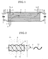
- Fig. 2 shows an embodiment according to the invention in which parts similar to those in Fig. 1 are designated by the same reference numerals.
- this embodiment is directed to an EGR cooler constructed substantially in the same manner as described above with respect to Fig. 1, and an inner periphery of the tube 3 through which exhaust gas 10 passes is formed with a plurality of streaks of spiral protrusions 12 and 13 with inclination angle ⁇ in a range of 26°-50° relative to a plane perpendicular to an axis of the tube 3.
- two streaks of spiral protrusions 12 and 13 run without crossing and with phases peripherally shifted at 180° to each other.
- the spiral protrusions 12 and 13 may be formed by spirally indenting the tube 3 from outside by means of, for example, a roll having spiral convex streaks, so that portions pressed from outside provide the spiral protrusions 12 and 13 on the inner periphery of the tube 3.
- the spiral protrusions 12 and 13 may be formed by cutting the inner periphery of the tube 3 so as to leave the spiral protrusions 12 and 13.
- the ridge height h of the spiral protrusions 12 and 13 to the inner periphery of the tube 3 is preferably 5-15% of the inner diameter d of the tube 3.
- the ridge height h of the spiral protrusions 12 and 13 being more than 15% would result in worthless increase of pressure loss; that being less than 5% would result in too small whirling force by the spiral protrusions 12 and 13 and loose the worth of forming the spiral protrusions 12 and 13.
- such inclination angle ⁇ of the spiral protrusions 12 and 13 set to the range of 26°-50° is slightly inferior in initial performance value on heat exchange efficiency in comparison with an inclination angle ⁇ of less than 26°, but keeps the exhaust gas 10 to have less pressure loss and causes it to flow smoothly with tendency of the soot not to accumulate on the inner periphery of the tube 3, and therefore is superior in eventual performance value on heat exchange efficiency after deterioration; in view of long use thereafter, it turns out that there is a prolonged time period with good heat exchange efficiency maintained.
- the spiral protrusions 12 and 13 When the inclination angle ⁇ of the spiral protrusions 12 and 13 is set to the range of 26°-50°, and if the single strand of spiral protrusion 12 is used as schematically shown in Fig. 5, the axial pitch P of the spiral protrusion 12 is inevitably increased; however, if two streaks of spiral protrusions 12 and 13 are used as schematically shown in Fig. 6, the spiral protrusions 12 and 13 may have inclination angle ⁇ of more than 26° while the axial pitch P of the spiral protrusions 12 and 13 may be shortened, whereby the whirling force of the exhaust gas 10 can be enhanced without increasing the pressure loss.
- the inclination angle ⁇ of the spiral protrusions 12 and 13 is set to the range of 26°-50° so that accumulation of the soot on the inner periphery of the tube 3 can be suppressed to maintain higher the eventual performance value after deterioration than that in the conventional design concept which merely focuses attention on initial performance value, whereby an EGR cooler can be provided which can be satisfactorily applied with no substantial lowering in performance to a diesel engine from which is discharged exhaust gas 10 rich with sooty contents.
- the inner periphery of the tube 3 is formed with two streaks of spiral protrusions 12 and 13 running without crossing and with phases peripherally shifted to each other, so that the axial pitch P of the protrusions 12 and 13 can be decreased with the inclination angle ⁇ of the spiral protrusions 12 and 13 being more than 26°, which enables whirling force of the exhaust gas 10 to be increased without increasing the pressure loss.
- an EGR cooler according to the invention exhibits the following excellent features and advantages.
Landscapes
- Engineering & Computer Science (AREA)
- Physics & Mathematics (AREA)
- Mechanical Engineering (AREA)
- General Engineering & Computer Science (AREA)
- Thermal Sciences (AREA)
- Geometry (AREA)
- Chemical & Material Sciences (AREA)
- Combustion & Propulsion (AREA)
- Heat-Exchange Devices With Radiators And Conduit Assemblies (AREA)
- Exhaust-Gas Circulating Devices (AREA)
Abstract
Description
Such inclination angle of the spiral protrusion set to 26°-50° is slightly inferior in initial performance value on heat exchange efficiency in comparison with an inclination angle of less than 26°, but keeps the exhaust gas to have less pressure loss and causes it to flow smoothly with tendency of the soot not to accumulate on the inner periphery of the tube, and therefore is superior in eventual performance value on heat exchange efficiency after deterioration; in view of long use thereafter, it turns out that there is a prolonged time period with good heat exchange efficiency maintained. In fact, it has been ensured by the inventor's experiments that the inclination angle of spiral protrusion set to less than 26° increases the pressure loss so that soot tends to accumulate in the tube, resulting in substantial lowering in performance. It has been also ensured that, with the inclination angle of the spiral protrusion in a range of 26°-50°, the eventual performance value after deterioration substantially stays flat.
On the other hand, it has been ensured that even with the inclination angle of more than 50°, it hardly contributes to lowering in pressure loss of the exhaust gas while an amount of heat exchanged tends to be drastically decreased by slight increase in inclination angle; moreover, insufficiency of whirling force afforded to the exhaust gas remarkably impairs the function of the soot in the exhaust gas gathering to the whirling axis; as a result, inversely there may be a tendency of the soot to accumulate on the inner periphery of the tube.
Moreover, according to the invention, preferably the inner periphery of the tube is formed with a plurality of strands of spiral protrusions running without crossing and with phases peripherally shifted to each other. This enables the axial pitch of the protrusions to be decreased with the inclination angle of the spiral protrusion of more than 26°, whereby whirling force of the exhaust gas can be increased without increasing the pressure loss.
When the inclination angle of the spiral protrusion is set to a range of 26°-50°, it is preferable that ridge height of the spiral protrusion to the inner periphery of the tube is 5-15% of the inner diameter of the tube.
Claims (4)
- An EGR cooler comprising tubes and a shell for enclosing said tubes, cooling water being supplied into and discharged from said shell, exhaust gas from a diesel engine being guided into said tubes to be heat exchanged with said cooling water, characterized in that an inner periphery of each of said tubes is formed with a spiral protrusion with an inclination angle in a range of 26°-50° to a plane perpendicular to an axis of the tube.
- The EGR cooler according to claim 1, characterized in that an inner periphery of each of the tubes is formed with a plurality of streaks of spiral protrusions running without crossing and with phases peripherally shifted to each other.
- The EGR cooler according to claim 1, characterized in that height of the spiral protrusion to an inner periphery of the tube is 5-15% of an inner diameter of the tube.
- The EGR cooler according to claim 2, characterized in that that height of the spiral protrusion to an inner periphery of the tube is 5-15% of an inner diameter of the tube.
Applications Claiming Priority (3)
| Application Number | Priority Date | Filing Date | Title |
|---|---|---|---|
| JP2002181757A JP2004028376A (en) | 2002-06-21 | 2002-06-21 | EGR cooler |
| JP2002181757 | 2002-06-21 | ||
| PCT/JP2003/006400 WO2004001314A1 (en) | 2002-06-21 | 2003-05-22 | Egr cooler |
Publications (2)
| Publication Number | Publication Date |
|---|---|
| EP1533584A1 true EP1533584A1 (en) | 2005-05-25 |
| EP1533584A4 EP1533584A4 (en) | 2005-10-26 |
Family
ID=29996631
Family Applications (1)
| Application Number | Title | Priority Date | Filing Date |
|---|---|---|---|
| EP03733025A Withdrawn EP1533584A4 (en) | 2002-06-21 | 2003-05-22 | Egr cooler |
Country Status (6)
| Country | Link |
|---|---|
| US (1) | US7080634B2 (en) |
| EP (1) | EP1533584A4 (en) |
| JP (1) | JP2004028376A (en) |
| KR (1) | KR20050013218A (en) |
| CN (1) | CN1662785A (en) |
| WO (1) | WO2004001314A1 (en) |
Cited By (2)
| Publication number | Priority date | Publication date | Assignee | Title |
|---|---|---|---|---|
| FR2891355A1 (en) * | 2005-09-29 | 2007-03-30 | Wevista Sa | Curved heat exchanger e.g. for Exhaust Gas Recycling (EGR) circuit comprises outer sleeve containing bundle of tubes with at least one twist |
| EP1933023A4 (en) * | 2005-10-07 | 2008-12-10 | Hino Motors Ltd | Egr cooler |
Families Citing this family (16)
| Publication number | Priority date | Publication date | Assignee | Title |
|---|---|---|---|---|
| US8272431B2 (en) * | 2005-12-27 | 2012-09-25 | Caterpillar Inc. | Heat exchanger using graphite foam |
| US7287522B2 (en) * | 2005-12-27 | 2007-10-30 | Caterpillar Inc. | Engine system having carbon foam exhaust gas heat exchanger |
| CN100472166C (en) * | 2006-04-21 | 2009-03-25 | 北京美联桥科技发展有限公司 | An exhaust gas recirculation heat exchanger |
| US8978740B2 (en) * | 2006-06-22 | 2015-03-17 | Modine Manufacturing Company | Heat exchanger |
| US9403204B2 (en) * | 2010-01-29 | 2016-08-02 | Modine Manufacturing Company | Heat exchanger assembly and method |
| US8069912B2 (en) | 2007-09-28 | 2011-12-06 | Caterpillar Inc. | Heat exchanger with conduit surrounded by metal foam |
| US7461641B1 (en) * | 2007-10-18 | 2008-12-09 | Ford Global Technologies, Llc | EGR Cooling System with Multiple EGR Coolers |
| DE102009020306A1 (en) * | 2008-05-12 | 2010-02-11 | Modine Manufacturing Co., Racine | Heat exchanger and method of assembly |
| WO2010103130A2 (en) | 2009-03-13 | 2010-09-16 | Katholieke Universiteit Leuven, K.U.Leuven R&D | Novel bicyclic heterocycles |
| GB201012889D0 (en) | 2010-08-02 | 2010-09-15 | Univ Leuven Kath | Antiviral activity of novel bicyclic heterocycles |
| GB201015411D0 (en) | 2010-09-15 | 2010-10-27 | Univ Leuven Kath | Anti-cancer activity of novel bicyclic heterocycles |
| DE102011007748A1 (en) * | 2011-04-20 | 2012-10-25 | Behr Gmbh & Co. Kg | An exhaust gas cooler for cooling combustion exhaust gas of an internal combustion engine, a water collection adapter, an exhaust gas cooling system, and a method of manufacturing an exhaust gas cooling system |
| US20140116668A1 (en) * | 2012-10-31 | 2014-05-01 | GM Global Technology Operations LLC | Cooler pipe and method of forming |
| CN103697740A (en) * | 2013-12-18 | 2014-04-02 | 杭州汉惠通用设备有限公司 | Inner petal-shaped irregular-shaped heat exchange tube |
| GB2542995A (en) * | 2014-07-21 | 2017-04-05 | Dana Canada Corp | Heat exchanger with flow obstructions to reduce fluid dead zones |
| CN114278469B (en) * | 2021-12-30 | 2022-10-21 | 重庆望江摩托车制造有限公司 | A hybrid energy motorcycle using methanol cracking to produce hydrogen |
Family Cites Families (15)
| Publication number | Priority date | Publication date | Assignee | Title |
|---|---|---|---|---|
| US3088494A (en) * | 1959-12-28 | 1963-05-07 | Babcock & Wilcox Co | Ribbed vapor generating tubes |
| US3826304A (en) * | 1967-10-11 | 1974-07-30 | Universal Oil Prod Co | Advantageous configuration of tubing for internal boiling |
| US4081913A (en) * | 1976-07-26 | 1978-04-04 | Salminen Reijo K | Pulp and paper drying apparatus and method |
| US4118944A (en) * | 1977-06-29 | 1978-10-10 | Carrier Corporation | High performance heat exchanger |
| US4290389A (en) * | 1979-09-21 | 1981-09-22 | Combustion Engineering, Inc. | Once through sliding pressure steam generator |
| US4660630A (en) * | 1985-06-12 | 1987-04-28 | Wolverine Tube, Inc. | Heat transfer tube having internal ridges, and method of making same |
| US6164370A (en) * | 1993-07-16 | 2000-12-26 | Olin Corporation | Enhanced heat exchange tube |
| JPH08128793A (en) * | 1994-10-28 | 1996-05-21 | Toshiba Corp | Heat transfer tube with internal fin and manufacturing method thereof |
| US5655599A (en) | 1995-06-21 | 1997-08-12 | Gas Research Institute | Radiant tubes having internal fins |
| JPH11108578A (en) * | 1997-09-30 | 1999-04-23 | Usui Internatl Ind Co Ltd | Egr gas cooler |
| US6684938B2 (en) * | 1999-01-20 | 2004-02-03 | Hino Motors, Ltd. | EGR cooler |
| EP1238193B1 (en) * | 1999-12-14 | 2007-05-23 | Cooper-Standard Automotive Inc. | Integrated egr valve and cooler |
| JP2001254649A (en) * | 2000-03-13 | 2001-09-21 | Hino Motors Ltd | EGR cooler |
| JP2001304047A (en) * | 2000-04-24 | 2001-10-31 | Usui Internatl Ind Co Ltd | Egr gas cooling device |
| US6883597B2 (en) * | 2001-04-17 | 2005-04-26 | Wolverine Tube, Inc. | Heat transfer tube with grooved inner surface |
-
2002
- 2002-06-21 JP JP2002181757A patent/JP2004028376A/en active Pending
-
2003
- 2003-05-22 EP EP03733025A patent/EP1533584A4/en not_active Withdrawn
- 2003-05-22 US US10/517,313 patent/US7080634B2/en not_active Expired - Lifetime
- 2003-05-22 WO PCT/JP2003/006400 patent/WO2004001314A1/en not_active Ceased
- 2003-05-22 CN CN038145936A patent/CN1662785A/en active Pending
- 2003-05-22 KR KR10-2004-7020712A patent/KR20050013218A/en not_active Ceased
Cited By (3)
| Publication number | Priority date | Publication date | Assignee | Title |
|---|---|---|---|---|
| FR2891355A1 (en) * | 2005-09-29 | 2007-03-30 | Wevista Sa | Curved heat exchanger e.g. for Exhaust Gas Recycling (EGR) circuit comprises outer sleeve containing bundle of tubes with at least one twist |
| EP1770343A1 (en) * | 2005-09-29 | 2007-04-04 | Wevista | Bended heat exchanger |
| EP1933023A4 (en) * | 2005-10-07 | 2008-12-10 | Hino Motors Ltd | Egr cooler |
Also Published As
| Publication number | Publication date |
|---|---|
| WO2004001314A1 (en) | 2003-12-31 |
| US7080634B2 (en) | 2006-07-25 |
| JP2004028376A (en) | 2004-01-29 |
| US20050199228A1 (en) | 2005-09-15 |
| EP1533584A4 (en) | 2005-10-26 |
| KR20050013218A (en) | 2005-02-03 |
| CN1662785A (en) | 2005-08-31 |
Similar Documents
| Publication | Publication Date | Title |
|---|---|---|
| US7080634B2 (en) | EGR cooler | |
| US7594536B2 (en) | EGR cooler | |
| CN101400959B (en) | heat exchangers for cars | |
| CN100526789C (en) | Exhaust gas heat exchanger, in particular exhaust gas cooler for exhaust gas recirculation of motor vehicles | |
| EP2025913B1 (en) | Three-pass heat exchanger for an EGR system | |
| JP2014025695A (en) | Heat exchanger for cooling vehicle exhaust gas | |
| US7481040B2 (en) | Exhaust-gas heat exchanger, in particular exhaust-gas cooler for exhaust gas recirculation in motor vehicles | |
| US8079409B2 (en) | EGR cooler | |
| JP2002054511A (en) | EGR cooler | |
| JP4345470B2 (en) | Engine EGR cooler | |
| JP2000234566A (en) | Egr gas cooling device | |
| JP2006118436A (en) | Bonnet for egr gas cooling device | |
| CN1466651A (en) | Internal combustion engine exhaust system with catalytic converter | |
| JP2005273512A (en) | Engine EGR cooler | |
| JP2002180915A (en) | EGR cooler | |
| US20080245502A1 (en) | Heat Exchanger | |
| JP2001254649A (en) | EGR cooler | |
| JP2001342912A (en) | EGR cooler | |
| KR20190072416A (en) | Device for heat transfer | |
| JP2000345925A (en) | EGR cooler | |
| KR20150026006A (en) | Heat Exchanger Tube Having Groove and Manufacturing Method Thereof | |
| CN100489437C (en) | Shell-and-tube type heat exchanger employing crossed spiral tube | |
| JP4744746B2 (en) | Heat transfer tube and multi-tube heat exchanger using this heat transfer tube and radiator built-in oil cooler | |
| JPH11287588A (en) | EGR cooler | |
| JP2007303296A (en) | EGR cooler |
Legal Events
| Date | Code | Title | Description |
|---|---|---|---|
| PUAI | Public reference made under article 153(3) epc to a published international application that has entered the european phase |
Free format text: ORIGINAL CODE: 0009012 |
|
| 17P | Request for examination filed |
Effective date: 20041222 |
|
| AK | Designated contracting states |
Kind code of ref document: A1 Designated state(s): AT BE BG CH CY CZ DE DK EE ES FI FR GB GR HU IE IT LI LU MC NL PT RO SE SI SK TR |
|
| RBV | Designated contracting states (corrected) |
Designated state(s): DE |
|
| A4 | Supplementary search report drawn up and despatched |
Effective date: 20050912 |
|
| RIC1 | Information provided on ipc code assigned before grant |
Ipc: 7F 28F 1/06 B Ipc: 7F 02M 25/07 B Ipc: 7F 28F 1/40 B Ipc: 7F 28D 7/16 A |
|
| RIN1 | Information on inventor provided before grant (corrected) |
Inventor name: YAMASHITA, YOJI,C/O SANKYO RADIATOR CO., LTD. |
|
| 17Q | First examination report despatched |
Effective date: 20100105 |
|
| STAA | Information on the status of an ep patent application or granted ep patent |
Free format text: STATUS: THE APPLICATION IS DEEMED TO BE WITHDRAWN |
|
| 18D | Application deemed to be withdrawn |
Effective date: 20100518 |