EP1533525A1 - Pump unit - Google Patents
Pump unit Download PDFInfo
- Publication number
- EP1533525A1 EP1533525A1 EP03730748A EP03730748A EP1533525A1 EP 1533525 A1 EP1533525 A1 EP 1533525A1 EP 03730748 A EP03730748 A EP 03730748A EP 03730748 A EP03730748 A EP 03730748A EP 1533525 A1 EP1533525 A1 EP 1533525A1
- Authority
- EP
- European Patent Office
- Prior art keywords
- pressure
- pump
- discharge line
- mode
- variable
- Prior art date
- Legal status (The legal status is an assumption and is not a legal conclusion. Google has not performed a legal analysis and makes no representation as to the accuracy of the status listed.)
- Granted
Links
Images


Classifications
-
- F—MECHANICAL ENGINEERING; LIGHTING; HEATING; WEAPONS; BLASTING
- F04—POSITIVE - DISPLACEMENT MACHINES FOR LIQUIDS; PUMPS FOR LIQUIDS OR ELASTIC FLUIDS
- F04B—POSITIVE-DISPLACEMENT MACHINES FOR LIQUIDS; PUMPS
- F04B49/00—Control, e.g. of pump delivery, or pump pressure of, or safety measures for, machines, pumps, or pumping installations, not otherwise provided for, or of interest apart from, groups F04B1/00 - F04B47/00
- F04B49/002—Hydraulic systems to change the pump delivery
-
- F—MECHANICAL ENGINEERING; LIGHTING; HEATING; WEAPONS; BLASTING
- F04—POSITIVE - DISPLACEMENT MACHINES FOR LIQUIDS; PUMPS FOR LIQUIDS OR ELASTIC FLUIDS
- F04B—POSITIVE-DISPLACEMENT MACHINES FOR LIQUIDS; PUMPS
- F04B49/00—Control, e.g. of pump delivery, or pump pressure of, or safety measures for, machines, pumps, or pumping installations, not otherwise provided for, or of interest apart from, groups F04B1/00 - F04B47/00
- F04B49/007—Installations or systems with two or more pumps or pump cylinders, wherein the flow-path through the stages can be changed, e.g. from series to parallel
-
- F—MECHANICAL ENGINEERING; LIGHTING; HEATING; WEAPONS; BLASTING
- F04—POSITIVE - DISPLACEMENT MACHINES FOR LIQUIDS; PUMPS FOR LIQUIDS OR ELASTIC FLUIDS
- F04B—POSITIVE-DISPLACEMENT MACHINES FOR LIQUIDS; PUMPS
- F04B49/00—Control, e.g. of pump delivery, or pump pressure of, or safety measures for, machines, pumps, or pumping installations, not otherwise provided for, or of interest apart from, groups F04B1/00 - F04B47/00
- F04B49/06—Control using electricity
-
- F—MECHANICAL ENGINEERING; LIGHTING; HEATING; WEAPONS; BLASTING
- F04—POSITIVE - DISPLACEMENT MACHINES FOR LIQUIDS; PUMPS FOR LIQUIDS OR ELASTIC FLUIDS
- F04B—POSITIVE-DISPLACEMENT MACHINES FOR LIQUIDS; PUMPS
- F04B49/00—Control, e.g. of pump delivery, or pump pressure of, or safety measures for, machines, pumps, or pumping installations, not otherwise provided for, or of interest apart from, groups F04B1/00 - F04B47/00
- F04B49/06—Control using electricity
- F04B49/065—Control using electricity and making use of computers
-
- F—MECHANICAL ENGINEERING; LIGHTING; HEATING; WEAPONS; BLASTING
- F04—POSITIVE - DISPLACEMENT MACHINES FOR LIQUIDS; PUMPS FOR LIQUIDS OR ELASTIC FLUIDS
- F04B—POSITIVE-DISPLACEMENT MACHINES FOR LIQUIDS; PUMPS
- F04B49/00—Control, e.g. of pump delivery, or pump pressure of, or safety measures for, machines, pumps, or pumping installations, not otherwise provided for, or of interest apart from, groups F04B1/00 - F04B47/00
- F04B49/08—Regulating by delivery pressure
-
- F—MECHANICAL ENGINEERING; LIGHTING; HEATING; WEAPONS; BLASTING
- F04—POSITIVE - DISPLACEMENT MACHINES FOR LIQUIDS; PUMPS FOR LIQUIDS OR ELASTIC FLUIDS
- F04C—ROTARY-PISTON, OR OSCILLATING-PISTON, POSITIVE-DISPLACEMENT MACHINES FOR LIQUIDS; ROTARY-PISTON, OR OSCILLATING-PISTON, POSITIVE-DISPLACEMENT PUMPS
- F04C14/00—Control of, monitoring of, or safety arrangements for, machines, pumps or pumping installations
- F04C14/02—Control of, monitoring of, or safety arrangements for, machines, pumps or pumping installations specially adapted for several machines or pumps connected in series or in parallel
-
- F—MECHANICAL ENGINEERING; LIGHTING; HEATING; WEAPONS; BLASTING
- F04—POSITIVE - DISPLACEMENT MACHINES FOR LIQUIDS; PUMPS FOR LIQUIDS OR ELASTIC FLUIDS
- F04C—ROTARY-PISTON, OR OSCILLATING-PISTON, POSITIVE-DISPLACEMENT MACHINES FOR LIQUIDS; ROTARY-PISTON, OR OSCILLATING-PISTON, POSITIVE-DISPLACEMENT PUMPS
- F04C14/00—Control of, monitoring of, or safety arrangements for, machines, pumps or pumping installations
- F04C14/06—Control of, monitoring of, or safety arrangements for, machines, pumps or pumping installations specially adapted for stopping, starting, idling or no-load operation
-
- F—MECHANICAL ENGINEERING; LIGHTING; HEATING; WEAPONS; BLASTING
- F04—POSITIVE - DISPLACEMENT MACHINES FOR LIQUIDS; PUMPS FOR LIQUIDS OR ELASTIC FLUIDS
- F04C—ROTARY-PISTON, OR OSCILLATING-PISTON, POSITIVE-DISPLACEMENT MACHINES FOR LIQUIDS; ROTARY-PISTON, OR OSCILLATING-PISTON, POSITIVE-DISPLACEMENT PUMPS
- F04C14/00—Control of, monitoring of, or safety arrangements for, machines, pumps or pumping installations
- F04C14/08—Control of, monitoring of, or safety arrangements for, machines, pumps or pumping installations characterised by varying the rotational speed
-
- F—MECHANICAL ENGINEERING; LIGHTING; HEATING; WEAPONS; BLASTING
- F04—POSITIVE - DISPLACEMENT MACHINES FOR LIQUIDS; PUMPS FOR LIQUIDS OR ELASTIC FLUIDS
- F04C—ROTARY-PISTON, OR OSCILLATING-PISTON, POSITIVE-DISPLACEMENT MACHINES FOR LIQUIDS; ROTARY-PISTON, OR OSCILLATING-PISTON, POSITIVE-DISPLACEMENT PUMPS
- F04C2270/00—Control; Monitoring or safety arrangements
- F04C2270/56—Number of pump/machine units in operation
Definitions
- the present invention relates to a pump unit.
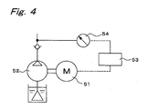
- This pump unit has a fixed-capacity type pump 52 whose rotational speed is variably driven by a variable-speed motor 51, and a controller 53 for controlling the rotational speed of the variable-speed motor 51 by changing the frequency of supply current to the motor 51.
- This controller 53 upon receiving a signal from a pressure sensor 54 which detects a pressure of a discharge line of the pump 52, controls the rotational speed of the variable-speed motor 51 so that the value of the pressure detected by the pressure sensor 54 becomes a specified value, thus controlling the rotational speed of the pump 52.
- an object of the present invention is to provide a pump unit capable of obtaining a high discharge pressure with use of a relatively small-torque motor, and yet capable of reducing noise and vibrations, during high flow-rate operations.
- a pump unit of this invention comprises:
- the switching valve in the first mode, the switching valve is switched over into a state that the first discharge line and the second discharge line are disconnected with each other, making the first fixed-capacity type pump unloaded.
- the control device which has received a signal from the pressure sensor and a signal representing a rotational speed of the variable-speed motor, the variable-speed motor is controlled so that a constant-horsepower operation in the first mode is performed.
- the switching valve in the second mode, is switched over into a state that the first discharge line and the second discharge line are connected with each other, in which state the variable-speed motor is controlled by the control device that has received a signal from the pressure sensor and a signal representing the rotational speed of the variable-speed motor, where a constant-horsepower operation is performed.
- variable-speed motor is controlled by the control device so that a constant-horsepower operation is performed
- discharge pressure and flow rate are autonomously controlled without receiving any command signal from external of the pump unit. Therefore, input signal lines for commands can be omitted, allowing the wiring to be simplified, and moreover operations for inputs of the command signals become unnecessary, thus making the pump unit easier to operate.
- control device switches the switching valve from connecting state to disconnecting state when the rotational speed of the variable-speed motor has decreased below a predetermined set rotational speed, and switches the switching valve from disconnecting state to connecting state when the pressure detected by the pressure sensor has decreased below a predetermined set pressure.
- the switching valve is switched over from connecting state to disconnecting state based on the rotational speed of the variable-speed motor, while the switching valve is switched over from disconnecting state to connecting state based on the detected pressure by the pressure sensor. Therefore, since the dead band of control inevitably becomes larger in width, it can be prevented that the switching valve becomes unstable between connecting state and disconnecting state. As a result, hunting of pressure and flow rate of the discharge fluid of the pump unit can be prevented.
- the control device since a constant-horsepower operation is performed by the control device, and since the switching valve is switched over based on the rotational speed of the motor and the detected value of the pressure sensor, the control of discharge pressure and flow rate as well as the switching of operational mode are autonomously controlled without receiving any command signal from external of the pump unit. Therefore, input signal lines for commands can be omitted, allowing the wiring to be simplified, and moreover operations for inputs of the command signals become unnecessary, thus making the pump unit easier to operate.
- control device switches the switching valve from disconnecting state to connecting state when the rotational speed of the variable-speed motor has increased over a predetermined set rotational speed, and switches the switching valve from connecting state to disconnecting state when the pressure detected by the pressure sensor has increased over a predetermined set pressure.
- the switching valve is switched over from disconnecting state to connecting state based on the rotational speed of the variable-speed motor, while the switching valve is switched over from connecting state to disconnecting state based on the detected pressure by the pressure sensor. Therefore, since the dead band of control inevitably becomes larger in width, it can be prevented that the switching valve becomes unstable between connecting state and disconnecting state. As a result, hunting of pressure and flow rate of the discharge fluid of the pump unit can be prevented.
- the control device since a constant-horsepower operation is performed by the control device, and since the switching valve is switched over based on the rotational speed of the motor and the detected value of the pressure sensor, the control of discharge pressure and flow rate as well as the switching of operational mode are autonomously controlled without receiving any command signal from external of the pump unit. Therefore, input signal lines for commands can be omitted, allowing the wiring to be simplified, and moreover operations for inputs of the command signals become unnecessary, thus making the pump unit easier to operate.
- control device includes an input section from which the set rotational speed and the set pressure are variably inputted so that the first mode and the second mode are operable in a plurality of modes, respectively.
- the pump unit by the input section, a plurality of settings are inputted for the set rotational speed and the set pressure, respectively, so that the first mode and the second mode are operable in a plurality of modes, respectively.
- the pump unit can work appropriately for characteristics or operating conditions or the like of equipment to which the pump unit feeds the fluid.
- Fig. 1 is a view showing a pump unit of an embodiment of the present invention.
- This pump unit is a pump unit that feeds a working fluid of a tank T to an unshown actuator such as hydraulic cylinder.
- This pump unit has a first pump 1 as a first fixed-capacity type pump of large capacity, and a second pump 2 as a second fixed-capacity type pump of small capacity directly connected to the first pump 1.
- the first pump 1 is a gear pump of 5.5 cc/rev.
- the second pump 2 is a gear pump of 3.5 cc/rev.
- These first pump 1 and second pump 2 are connected to a variable-speed motor 3, and this variable-speed motor 3 is electrically connected to a control device 4.
- An outlet port of the first pump 1 is connected to a first discharge line 5, and an outlet port of the second pump 2 is connected to a second discharge line 8.
- the first discharge line 5 is connected to a switching valve 6 so as to be switchable by this switching valve 6 to the second discharge line 8 or a drain line 11 leading to a tank 10.
- the second discharge line 8 is connected to an unshown actuator via a check valve-equipped flow-rate control valve 9.
- the second discharge line 8 is connected to the drain line 11 via a restrictor 13 for leaking a specified amount of working fluid, and also connected to the drain line 11 via a relief valve 14 provided in parallel to the restrictor 13.
- a pressure sensor 17 for detecting discharge pressures of the first and second pumps 1, 2 is provided on the second discharge line 8.
- the first discharge line 5 is connected to the drain line 11 via a relief valve 15.
- the control device 4 is electrically connected to an input section 19, to which such settings as maximum pressure and maximum flow rate of the working fluid discharged from the second discharge line 8 are inputted. Further, the control device 4 is electrically connected to the pressure sensor 17 and moreover connected to the motor 3 so as to be able to receive a signal indicating the rotational speed of the variable-speed motor 3.
- the control device 4 is composed of an inverter section for outputting a drive current to the variable-speed motor 3, and a control section which is implemented by a microcomputer and which controls the frequency of an output current of the inverter section.
- this control device calculates pressure-flow rate characteristics to be fulfilled by the first and second pumps 1, 2. Based on the pressure-flow rate characteristics, a current pressure value derived from the pressure sensor 17 and a current rotational speed of the variable-speed motor 3, the control section controls the rotational speed of the variable-speed motor 3 via the inverter section, and further controls the switching state of the switching valve 6.
- the control section of the control device 4 is so made up as to control the variable-speed motor 3 and the switching valve 6 in a first mode and a second mode.
- the first discharge line 5 is disconnected from the second discharge line 8, and a constant-horsepower operation is performed with the first pump 1 unloaded. That is, only the discharge fluid of the second pump 2 is fed out to the actuator via the second discharge line 8.
- constant-horsepower operation is performed with the first discharge line 5 connected to the second discharge line 8. In other words, the discharge fluid of both the first and second pumps 1, 2 is transmitted to the actuator via the second discharge line 8.
- Fig. 2 is a chart in which values of pressure-flow rate characteristics calculated by the control section of the control device 4 based on information inputted from the input section 19 are represented in two-dimensional coordinates showing flow rate in the vertical axis and pressure in the horizontal axis.
- this pressure-flow rate characteristic line is composed of a first-mode portion and a second-mode portion connected to each other at a changeover point CP.
- the first-mode portion of the pressure-flow rate characteristic line which is a portion related to the discharge fluid of the second pump 2 alone, is comprised of a maximum pressure line MP1, a maximum horsepower curve MHP1 and a maximum flow-rate line MV1.
- the second-mode portion of the pressure-flow rate characteristic line which is a portion related to the discharge fluid of the merged flow of the first and second pumps 1, 2, is comprised of a maximum pressure line MP2, a maximum horsepower curve MHP2 and a maximum flow-rate line MV2.
- the control section plots in the coordinates of Fig. 2 a current point determined by a current discharge pressure detected by the pressure sensor 17 and a current discharge flow rate corresponding to the rotational speed of the variable-speed motor 3.
- a current horsepower at this current point is calculated, and a deviation from a target horsepower on the pressure-flow rate characteristic line is determined.
- a control signal representing this deviation is inputted to the inverter section, and the rotational speed of the variable-speed motor 3 is controlled so as to make the current horsepower coincident with the target horsepower.
- pressure and flow rate of the discharge fluid derived from the second discharge line 8 fall on the pressure-flow rate characteristic line of Fig. 2. Consequently, the output of the pump unit is autonomously controlled to a maximum without depending on any command or input from external.
- the control device 4 makes the variable-speed motor 3 rotated at a low speed so that the pressure is held at an utmost set pressure Pm in a state of small discharge flow rate. Accordingly, it no longer occurs that the variable-speed motor 3 or the second pump 2 rotates at more than necessary rotational speeds, so that the loss of horsepower is suppressed to a small one, allowing an energy saving to be achieved, and moreover noise can be reduced.
- the control device 4 makes the variable-speed motor 3 via the inverter section so that discharge pressures of the first and second pumps 1, 2 become small pressures of points on the maximum flow-rate line MV2 generally parallel to the horizontal axis (pressure axis) of Fig. 2. Accordingly, it no longer occurs that the variable-speed motor 3 or the first and second pumps 1, 2 rotate at more than necessary rotational speeds, so that the loss of horsepower is suppressed to a small one, allowing an energy saving to be achieved, and moreover noise can be reduced.
- the pump unit of this embodiment in which the control of the rotational speed of the variable-speed motor 3 and the switching of the switching valve 6 are performed by the control device 4, is autonomously operable without depending on any command from external of the pump unit. Therefore, this pump unit is easy to operate. Also, since there are no needs for wiring or the like for reception of commands from the external, wiring for the pump unit can be reduced so that the vicinities of the installation place of this pump unit can be arranged tidily and moreover the installation work for the pump unit can be simplified.
- the control device 4 that has detected a decrease of the discharge pressure by the signal from the pressure sensor 17 switches over the switching valve 6. That is, the control device 4 applies a specified voltage to the solenoid of the switching valve 6 to make the first discharge line 5 connected to the second discharge line 8. Then, the control device 4 controls the rotational speed of the variable-speed motor 3 so that the merged discharge fluid of the first and second pumps 1, 2 falls on the maximum horsepower curve MHP2.
- the control device 4 that has detected a decrease of their discharge flow rates from the rotational speed of the motor switches over the switching valve 6. That is, the control device 4 changes the application voltage to the solenoid of the switching valve 6, thereby changing the valve position, so as to make the first discharge line 5 disconnected from the second discharge line 8. Then, the control device 4 controls the rotational speed of the variable-speed motor 3 so that its output horsepower for the discharge fluid of the second pump 2 alone, from which the first pump 1 has been disconnected, falls on the maximum horsepower curve MHP1 of Fig. 2.
- the switching of the switching valve 6 from disconnecting state to connecting state is effected based on the discharge pressure of the second discharge line 8, while its switching from connecting state to disconnecting state is effected based on the discharge flow rate of the second discharge line 8. That is, the switching from disconnecting state to connecting state and the switching from connecting state to disconnecting state are effected based on mutually different detection targets. Accordingly, since the dead band of control becomes larger in width, it never occurs that the switching valve 6 is frequently switched over between connecting state and disconnecting state so as to become unstable, even if detection-targeted pressure and flow rate are increased or decreased in the vicinity of their switching reference values. As a result, hunting of flow rate and pressure of the discharge fluid can be prevented, so that the output horsepower of the pump unit can be stabilized.
- the pump unit of this embodiment can be controlled based on pressure-flow rate characteristics of patterns different from the pattern shown in Fig. 2 by changing the input values of maximum pressure or maximum flow rate or the like inputted via the input section 19.
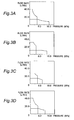
- Figs. 3A, 3B, 3C, 3D are views showing pressure-flow rate characteristics obtained with inputs of changed input values of maximum pressure, maximum flow rate and maximum horsepower by way of example.
- the values of maximum horsepower are set for the first-mode portion and the second-mode portion independently of each other, and besides the pressure value at which the first mode changes to the second mode, the flow rate value at which the second mode changes to the first mode, and the like are set independently of each other.
- pressure-flow rate characteristics of the discharge fluid can appropriately be set according to the characteristics of the actuator or the like to which the pump unit feeds the working fluid. Therefore, this pump unit can feed working fluid to a plurality of actuators of different characteristics at appropriate pressure-flow rate characteristics, and moreover can manage a plurality of operating conditions of the actuator.
- the switching valve 6 is switched over from connecting state to disconnecting state when the rotational speed of the variable-speed motor 3 has decreased below a predetermined set rotational speed, and that the switching valve 6 is switched over from disconnecting state to connecting state when the pressure detected by the pressure sensor 17 has decreased below a predetermined set pressure of Pc.
- the control may be reverse to this. That is, it may also be arranged that the switching valve 6 is switched over from disconnecting state to connecting state when the rotational speed of the variable-speed motor 3 has increased over a predetermined set rotational speed, and that the switching valve 6 is switched over from connecting state to disconnecting state when the pressure detected by the pressure sensor 17 has increased over a predetermined set pressure of Pc.
- the first and second pumps 1, 2 are implemented by gear pumps.
- pumps other than gear pumps such as trochoid pumps, vane pumps or piston pumps are also usable, and any type of pump will do only if it is a fixed-capacity type pump.
- the pressure-flow rate characteristic line is composed of a maximum flow-rate line, a maximum horsepower curve and a maximum pressure line.
- a pseudo maximum horsepower line made of inclined line or polygonal line may be used instead of the maximum horsepower curve.
- the target pressure-flow rate characteristic line may be arbitrary curved line or polygonal line that is most preferable from the operation's point of view.
- an utmost set pressure, a maximum set flow rate, a maximum set horsepower are to be set via the input section 19.
- an utmost set pressure, a maximum set flow rate and a maximum set horsepower may be programmed in those mediums after or before shipping of the pump unit.
- flow rate of the discharge fluid is determined from the rotational speed of the variable-speed motor 3.
- it is also possible to directly detect the flow rate of the discharge fluid for example, by setting a flow meter on the second discharge line 8.
Landscapes
- Engineering & Computer Science (AREA)
- Mechanical Engineering (AREA)
- General Engineering & Computer Science (AREA)
- Computer Hardware Design (AREA)
- Control Of Positive-Displacement Pumps (AREA)
- Eye Examination Apparatus (AREA)
- Details And Applications Of Rotary Liquid Pumps (AREA)
- Control Of Fluid Gearings (AREA)
Abstract
Description
Claims (4)
- A pump unit comprising:a first fixed-capacity type pump (1) having large capacity;a second fixed-capacity type pump (2) having small capacity;a first discharge line (5) connected to the first fixed-capacity type pump (1);a second discharge line (8) connected to the second fixed-capacity type pump (2);a variable-speed motor (3) for driving the first and second fixed-capacity type pumps (1, 2);a switching valve (6) for making the first discharge line (5) and the second discharge line (8) connected or disconnected with each other;a pressure sensor (17) for detecting a pressure of the second discharge line (8); anda control device (4) for, upon reception of a signal from the pressure sensor (17) and a signal representing a rotational speed of the variable-speed motor (3), controlling the switching valve (6) and the variable-speed motor (3) so that operation is performed in a first mode and in a second mode, the first mode being a mode in which the first discharge line (5) and the second line (8) are disconnected with each other to make the first fixed-capacity type pump (1) unloaded, in which state a constant-horsepower operation is performed, and the second mode being a mode in which the first discharge line (5) and the second discharge line (8) are connected with each other, in which state a constant-horsepower operation is performed.
- The pump unit according to Claim 1, wherein
the control device (4) switches the switching valve (6) from connecting state to disconnecting state when the rotational speed of the variable-speed motor (3) has decreased below a predetermined set rotational speed, and switches the switching valve (6) from disconnecting state to connecting state when the pressure detected by the pressure sensor (17) has decreased below a predetermined set pressure (Pc). - The pump unit according to Claim 1, wherein
the control device (4) switches the switching valve (6) from disconnecting state to connecting state when the rotational speed of the variable-speed motor (3) has increased over a predetermined set rotational speed, and switches the switching valve (6) from connecting state to disconnecting state when the pressure detected by the pressure sensor (17) has increased over a predetermined set pressure (Pc). - The pump unit according to Claim 1, wherein
the control device (4) includes an input section (19) from which the set rotational speed and the set pressure are variably inputted so that the first mode and the second mode are operable in a plurality of modes, respectively.
Applications Claiming Priority (3)
| Application Number | Priority Date | Filing Date | Title |
|---|---|---|---|
| JP2002169554A JP4218261B2 (en) | 2002-06-11 | 2002-06-11 | Pumping unit |
| JP2002169554 | 2002-06-11 | ||
| PCT/JP2003/006907 WO2003104655A1 (en) | 2002-06-11 | 2003-06-02 | Pump unit |
Publications (3)
| Publication Number | Publication Date |
|---|---|
| EP1533525A1 true EP1533525A1 (en) | 2005-05-25 |
| EP1533525A4 EP1533525A4 (en) | 2005-09-14 |
| EP1533525B1 EP1533525B1 (en) | 2007-08-01 |
Family
ID=29727737
Family Applications (1)
| Application Number | Title | Priority Date | Filing Date |
|---|---|---|---|
| EP03730748A Expired - Lifetime EP1533525B1 (en) | 2002-06-11 | 2003-06-02 | Pump unit |
Country Status (9)
| Country | Link |
|---|---|
| US (1) | US7399165B2 (en) |
| EP (1) | EP1533525B1 (en) |
| JP (1) | JP4218261B2 (en) |
| KR (1) | KR100615808B1 (en) |
| CN (1) | CN100414103C (en) |
| AT (1) | ATE368804T1 (en) |
| DE (1) | DE60315307T2 (en) |
| TW (1) | TWI224175B (en) |
| WO (1) | WO2003104655A1 (en) |
Cited By (3)
| Publication number | Priority date | Publication date | Assignee | Title |
|---|---|---|---|---|
| EP2058518A4 (en) * | 2006-09-01 | 2014-05-14 | Aigeltec Ingenieria S L | Control device for a power unit |
| WO2016173981A1 (en) * | 2015-04-27 | 2016-11-03 | Continental Automotive Gmbh | Method for regulating a fuel delivery pump |
| EP3943749A1 (en) * | 2017-04-28 | 2022-01-26 | Graco Minnesota Inc. | Portable hydraulic power unit |
Families Citing this family (21)
| Publication number | Priority date | Publication date | Assignee | Title |
|---|---|---|---|---|
| US8337166B2 (en) * | 2001-11-26 | 2012-12-25 | Shurflo, Llc | Pump and pump control circuit apparatus and method |
| SE529328C2 (en) | 2005-11-15 | 2007-07-10 | Johan Stenberg | Control system and method for controlling electromagnetically driven pumps |
| CN101033744B (en) * | 2006-03-08 | 2013-07-24 | Itt制造企业公司 | Pump protection method and apparatus without conventional sensors |
| US8303260B2 (en) * | 2006-03-08 | 2012-11-06 | Itt Manufacturing Enterprises, Inc. | Method and apparatus for pump protection without the use of traditional sensors |
| US7950910B2 (en) | 2006-09-12 | 2011-05-31 | Spx Corporation | Piston cartridge |
| US8192173B2 (en) | 2006-09-12 | 2012-06-05 | Spx Corporation | Pressure compensated and constant horsepower pump |
| JP5207910B2 (en) * | 2008-10-09 | 2013-06-12 | 日立三菱水力株式会社 | Operation control method and operation control apparatus for variable speed generator motor |
| DE102009025707B4 (en) * | 2009-06-20 | 2021-06-02 | Robert Bosch Gmbh | Device for controlling a system with hydraulic circuits |
| US8801407B2 (en) * | 2010-02-24 | 2014-08-12 | Harris Waste Management Group, Inc. | Hybrid electro-hydraulic power device |
| JP5126339B2 (en) * | 2010-02-25 | 2013-01-23 | 株式会社デンソー | Fuel supply device |
| JP2011185190A (en) * | 2010-03-10 | 2011-09-22 | Ebara Corp | Control device integrated type motor pump |
| JP5760816B2 (en) * | 2011-08-01 | 2015-08-12 | ダイキン工業株式会社 | Pumping unit |
| CN103629094B (en) * | 2012-08-24 | 2016-12-21 | 罗伯特·博世有限公司 | Pump installation |
| KR101405207B1 (en) * | 2012-11-06 | 2014-06-10 | 현대자동차 주식회사 | Oil pressure supply system of automatic transmission |
| CN104675775B (en) * | 2013-12-03 | 2017-08-04 | 北汽福田汽车股份有限公司 | A kind of pump truck hydraulic system and pump truck |
| RU171643U1 (en) * | 2016-05-17 | 2017-06-08 | Акционерное общество "Государственный ракетный центр имени академика В.П. Макеева" | ADJUSTABLE PUMP INSTALLATION |
| US10995746B2 (en) * | 2017-01-17 | 2021-05-04 | Innio Jenbacher Gmbh & Co Og | Two-stage reciprocating compressor optimization control system |
| KR102496257B1 (en) * | 2017-12-19 | 2023-02-08 | 현대자동차주식회사 | Control method of electric oil pump |
| WO2020217934A1 (en) | 2019-04-25 | 2020-10-29 | 株式会社村田製作所 | Pump device |
| DE102020200261A1 (en) * | 2020-01-10 | 2021-07-15 | Putzmeister Engineering Gmbh | Method for operating a thick matter pump and thick matter pump |
| JP7597438B2 (en) | 2020-12-25 | 2024-12-10 | ミネベアミツミ株式会社 | PUMP SYSTEM, FLUID SUPPLY DEVICE, AND DRIVE CONTROL METHOD FOR PUMP SYSTEM - Patent application |
Family Cites Families (31)
| Publication number | Priority date | Publication date | Assignee | Title |
|---|---|---|---|---|
| SE369948B (en) * | 1969-12-03 | 1974-09-23 | I Soeyland | |
| DD108795A1 (en) | 1973-12-28 | 1974-10-05 | ||
| GB1515157A (en) | 1974-11-19 | 1978-06-21 | Bosch Gmbh Robert | Control device for hydraulic pumps |
| JPS51163501U (en) * | 1975-06-20 | 1976-12-27 | ||
| JPS5350502A (en) * | 1976-10-20 | 1978-05-09 | Naito Bunji | Oil and water pressure circuits for pumps variable in discharge pressure and flow rate |
| JPS5350504A (en) * | 1976-10-20 | 1978-05-09 | Naito Bunji | Combination of motors and fixed volume pumps and oil pressure circuits therefor |
| US4377708A (en) * | 1977-10-14 | 1983-03-22 | Monsanto Company | Hydrocarboxylation of vinyl alkanoates |
| DE3016943A1 (en) | 1980-05-02 | 1981-11-05 | Robert Bosch Gmbh, 7000 Stuttgart | HYDRAULIC SYSTEM WITH TWO PUMPS |
| US4500727A (en) * | 1981-03-23 | 1985-02-19 | Kuraray Co., Ltd. | Process for producing methyl lactate |
| US5228289A (en) * | 1983-06-29 | 1993-07-20 | Peter Norton | Plural hydraulic pump system with unloading valve |
| JPS60100594U (en) * | 1983-12-14 | 1985-07-09 | 株式会社 川本製作所 | automatic water supply device |
| JP2506436B2 (en) * | 1989-03-30 | 1996-06-12 | 日産自動車株式会社 | Vehicle fluid pressure supply device |
| JP2509328B2 (en) * | 1989-04-28 | 1996-06-19 | 日産自動車株式会社 | Vehicle fluid pressure supply device |
| JP2621611B2 (en) * | 1990-08-08 | 1997-06-18 | 日産自動車株式会社 | Fluid pressure supply device |
| US5199854A (en) * | 1990-08-08 | 1993-04-06 | Nissan Motor Co., Ltd. | Hydraulic supply arrangement for use with active automotive suspension or the like |
| BE1004336A3 (en) * | 1991-01-15 | 1992-11-03 | Analis Sa | SEPARATION PROCESS AND QUANTIFICATION HEMOGLOBIN A1C Glycosylated HB. |
| JPH05263768A (en) * | 1992-03-24 | 1993-10-12 | Toshiba Corp | Booster pump operation controller |
| DE59410267D1 (en) * | 1993-02-26 | 2003-05-15 | Syngenta Participations Ag | Ferrocenyldiphosphines as ligands for homogeneous catalysts |
| WO1996016971A1 (en) * | 1994-11-29 | 1996-06-06 | Lonza Ag | Method of producing optically active metallocenyl phosphines |
| EP0729969B1 (en) * | 1995-02-24 | 2000-08-16 | Novartis AG | Silated ferrocene-diphosphine ligands, inorganic or polymeric organic support to which these ligands are bound and metal complexes thereof, and their preparation and use |
| CZ291280B6 (en) * | 1995-04-11 | 2003-01-15 | Syngenta Participations Ag | Ferrocenes and processes of their preparation |
| SE9600748D0 (en) | 1996-02-27 | 1996-02-27 | Pharmacia Biotech Ab | Pump |
| US6184391B1 (en) * | 1997-04-15 | 2001-02-06 | Union Carbide Chemicals & Plastics Technology Corporation | Processes for producing epsilon caprolactones and/or hydrates and/or esters thereof |
| IT1291926B1 (en) * | 1997-06-06 | 1999-01-21 | Univ Roma | INFRARED RADIATION DETECTION SYSTEM BASED ON AMORPHOUS SILICON SENSORS AND ITS ALLOYS |
| EP0967015B1 (en) * | 1998-06-19 | 2005-01-12 | Degussa AG | Use of ferrocenyl ligands in catalytic enantioselective hydrogenation |
| US6337406B1 (en) * | 1998-08-21 | 2002-01-08 | The Penn State Research Foundation | Asymmetric catalysis based on chiral phospholanes and hydroxyl phospholanes |
| AU7590600A (en) * | 1999-09-20 | 2001-04-24 | Penn State Research Foundation, The | Chiral phosphines, transition metal complexes thereof and uses thereof in asymmetric reactions |
| US6258979B1 (en) * | 1999-11-22 | 2001-07-10 | Henri Kagan | Chiral ferrocene phosphines active in asymmetric catalysis |
| MY133839A (en) * | 2000-03-14 | 2007-11-30 | Shell Int Research | Process for the carbonylation of pentenenitrile |
| US20030105348A1 (en) * | 2001-11-19 | 2003-06-05 | Bunel Emilio E. | Process for making 5-cyanovaleric acid, adipic acid or dimethyl adipate |
| CN100516017C (en) * | 2002-02-19 | 2009-07-22 | 国际壳牌研究有限公司 | Process for the carbonylation of an ethylenically unsaturated compound and catalyst therefore |
-
2002
- 2002-06-11 JP JP2002169554A patent/JP4218261B2/en not_active Expired - Lifetime
-
2003
- 2003-06-02 EP EP03730748A patent/EP1533525B1/en not_active Expired - Lifetime
- 2003-06-02 AT AT03730748T patent/ATE368804T1/en not_active IP Right Cessation
- 2003-06-02 DE DE60315307T patent/DE60315307T2/en not_active Expired - Lifetime
- 2003-06-02 CN CNB038132753A patent/CN100414103C/en not_active Expired - Lifetime
- 2003-06-02 WO PCT/JP2003/006907 patent/WO2003104655A1/en not_active Ceased
- 2003-06-02 KR KR1020047019967A patent/KR100615808B1/en not_active Expired - Lifetime
- 2003-06-02 US US10/516,912 patent/US7399165B2/en not_active Expired - Lifetime
- 2003-06-11 TW TW092115864A patent/TWI224175B/en not_active IP Right Cessation
Cited By (4)
| Publication number | Priority date | Publication date | Assignee | Title |
|---|---|---|---|---|
| EP2058518A4 (en) * | 2006-09-01 | 2014-05-14 | Aigeltec Ingenieria S L | Control device for a power unit |
| WO2016173981A1 (en) * | 2015-04-27 | 2016-11-03 | Continental Automotive Gmbh | Method for regulating a fuel delivery pump |
| EP3943749A1 (en) * | 2017-04-28 | 2022-01-26 | Graco Minnesota Inc. | Portable hydraulic power unit |
| US11441551B2 (en) | 2017-04-28 | 2022-09-13 | Graco Minnesota Inc. | Portable hydraulic power unit |
Also Published As
| Publication number | Publication date |
|---|---|
| DE60315307D1 (en) | 2007-09-13 |
| CN100414103C (en) | 2008-08-27 |
| TW200407503A (en) | 2004-05-16 |
| EP1533525B1 (en) | 2007-08-01 |
| DE60315307T2 (en) | 2007-12-20 |
| JP2004011597A (en) | 2004-01-15 |
| US20050180855A1 (en) | 2005-08-18 |
| KR20050008807A (en) | 2005-01-21 |
| WO2003104655A1 (en) | 2003-12-18 |
| EP1533525A4 (en) | 2005-09-14 |
| ATE368804T1 (en) | 2007-08-15 |
| US7399165B2 (en) | 2008-07-15 |
| TWI224175B (en) | 2004-11-21 |
| JP4218261B2 (en) | 2009-02-04 |
| CN1659380A (en) | 2005-08-24 |
| KR100615808B1 (en) | 2006-08-25 |
Similar Documents
| Publication | Publication Date | Title |
|---|---|---|
| EP1533525B1 (en) | Pump unit | |
| JP3587957B2 (en) | Engine control device for construction machinery | |
| US6010309A (en) | Control device for variable capacity pump | |
| JP3533085B2 (en) | Pump control device for construction machinery | |
| EP1830066B1 (en) | Hydraulic control apparatus of working machine | |
| US9709076B2 (en) | Hydraulic drive system | |
| US6976358B2 (en) | Circuit for controlling discharge amount of hydraulic pump | |
| JP2008303985A (en) | Fluid pressure unit | |
| KR101050890B1 (en) | Hydraulic drive of working vehicle | |
| KR101514465B1 (en) | Hydraulic pump control device and control method of construction machine | |
| KR100984142B1 (en) | Hydraulic drive | |
| WO2009132180A2 (en) | Method of controlling a hydraulic system | |
| CN113286950A (en) | Slewing drive device for construction machine | |
| KR20090068823A (en) | Hydraulic pump flow control device for construction machinery | |
| JP3444503B2 (en) | Control device for hydraulic drive machine | |
| WO2024014083A1 (en) | Hydraulic system | |
| JP5760816B2 (en) | Pumping unit | |
| JP4148884B2 (en) | Engine lag down suppression device for construction machinery | |
| JPH06280809A (en) | Control device for hydraulic drive machine | |
| JPH04325784A (en) | Pump absorption torque control device | |
| JPH08246509A (en) | Hydraulic control device for boom working machine | |
| WO2024014082A1 (en) | Hydraulic system | |
| JP2003314501A (en) | Control device for hydraulic drive machine | |
| JPH074362A (en) | Variable capacity vane pump | |
| JPH06280808A (en) | Control device for hydraulically-operated machine |
Legal Events
| Date | Code | Title | Description |
|---|---|---|---|
| PUAI | Public reference made under article 153(3) epc to a published international application that has entered the european phase |
Free format text: ORIGINAL CODE: 0009012 |
|
| 17P | Request for examination filed |
Effective date: 20041214 |
|
| AK | Designated contracting states |
Kind code of ref document: A1 Designated state(s): AT BE BG CH CY CZ DE DK EE ES FI FR GB GR HU IE IT LI LU MC NL PT RO SE SI SK TR |
|
| A4 | Supplementary search report drawn up and despatched |
Effective date: 20050729 |
|
| RIC1 | Information provided on ipc code assigned before grant |
Ipc: 7F 04B 49/08 B Ipc: 7F 04B 49/06 A Ipc: 7F 04B 49/00 B |
|
| GRAP | Despatch of communication of intention to grant a patent |
Free format text: ORIGINAL CODE: EPIDOSNIGR1 |
|
| GRAS | Grant fee paid |
Free format text: ORIGINAL CODE: EPIDOSNIGR3 |
|
| GRAA | (expected) grant |
Free format text: ORIGINAL CODE: 0009210 |
|
| AK | Designated contracting states |
Kind code of ref document: B1 Designated state(s): AT BE BG CH CY CZ DE DK EE ES FI FR GB GR HU IE IT LI LU MC NL PT RO SE SI SK TR |
|
| REG | Reference to a national code |
Ref country code: GB Ref legal event code: FG4D |
|
| REG | Reference to a national code |
Ref country code: CH Ref legal event code: EP |
|
| REG | Reference to a national code |
Ref country code: IE Ref legal event code: FG4D |
|
| REF | Corresponds to: |
Ref document number: 60315307 Country of ref document: DE Date of ref document: 20070913 Kind code of ref document: P |
|
| PG25 | Lapsed in a contracting state [announced via postgrant information from national office to epo] |
Ref country code: FI Free format text: LAPSE BECAUSE OF FAILURE TO SUBMIT A TRANSLATION OF THE DESCRIPTION OR TO PAY THE FEE WITHIN THE PRESCRIBED TIME-LIMIT Effective date: 20070801 Ref country code: ES Free format text: LAPSE BECAUSE OF FAILURE TO SUBMIT A TRANSLATION OF THE DESCRIPTION OR TO PAY THE FEE WITHIN THE PRESCRIBED TIME-LIMIT Effective date: 20071112 Ref country code: BG Free format text: LAPSE BECAUSE OF FAILURE TO SUBMIT A TRANSLATION OF THE DESCRIPTION OR TO PAY THE FEE WITHIN THE PRESCRIBED TIME-LIMIT Effective date: 20071101 Ref country code: NL Free format text: LAPSE BECAUSE OF FAILURE TO SUBMIT A TRANSLATION OF THE DESCRIPTION OR TO PAY THE FEE WITHIN THE PRESCRIBED TIME-LIMIT Effective date: 20070801 |
|
| NLV1 | Nl: lapsed or annulled due to failure to fulfill the requirements of art. 29p and 29m of the patents act | ||
| REG | Reference to a national code |
Ref country code: CH Ref legal event code: PL |
|
| PG25 | Lapsed in a contracting state [announced via postgrant information from national office to epo] |
Ref country code: CH Free format text: LAPSE BECAUSE OF FAILURE TO SUBMIT A TRANSLATION OF THE DESCRIPTION OR TO PAY THE FEE WITHIN THE PRESCRIBED TIME-LIMIT Effective date: 20070801 Ref country code: LI Free format text: LAPSE BECAUSE OF FAILURE TO SUBMIT A TRANSLATION OF THE DESCRIPTION OR TO PAY THE FEE WITHIN THE PRESCRIBED TIME-LIMIT Effective date: 20070801 Ref country code: AT Free format text: LAPSE BECAUSE OF FAILURE TO SUBMIT A TRANSLATION OF THE DESCRIPTION OR TO PAY THE FEE WITHIN THE PRESCRIBED TIME-LIMIT Effective date: 20070801 |
|
| EN | Fr: translation not filed | ||
| PG25 | Lapsed in a contracting state [announced via postgrant information from national office to epo] |
Ref country code: BE Free format text: LAPSE BECAUSE OF FAILURE TO SUBMIT A TRANSLATION OF THE DESCRIPTION OR TO PAY THE FEE WITHIN THE PRESCRIBED TIME-LIMIT Effective date: 20070801 |
|
| PG25 | Lapsed in a contracting state [announced via postgrant information from national office to epo] |
Ref country code: GR Free format text: LAPSE BECAUSE OF FAILURE TO SUBMIT A TRANSLATION OF THE DESCRIPTION OR TO PAY THE FEE WITHIN THE PRESCRIBED TIME-LIMIT Effective date: 20071102 Ref country code: DK Free format text: LAPSE BECAUSE OF FAILURE TO SUBMIT A TRANSLATION OF THE DESCRIPTION OR TO PAY THE FEE WITHIN THE PRESCRIBED TIME-LIMIT Effective date: 20070801 |
|
| PG25 | Lapsed in a contracting state [announced via postgrant information from national office to epo] |
Ref country code: SK Free format text: LAPSE BECAUSE OF FAILURE TO SUBMIT A TRANSLATION OF THE DESCRIPTION OR TO PAY THE FEE WITHIN THE PRESCRIBED TIME-LIMIT Effective date: 20070801 Ref country code: PT Free format text: LAPSE BECAUSE OF FAILURE TO SUBMIT A TRANSLATION OF THE DESCRIPTION OR TO PAY THE FEE WITHIN THE PRESCRIBED TIME-LIMIT Effective date: 20080102 Ref country code: CZ Free format text: LAPSE BECAUSE OF FAILURE TO SUBMIT A TRANSLATION OF THE DESCRIPTION OR TO PAY THE FEE WITHIN THE PRESCRIBED TIME-LIMIT Effective date: 20070801 |
|
| PLBE | No opposition filed within time limit |
Free format text: ORIGINAL CODE: 0009261 |
|
| STAA | Information on the status of an ep patent application or granted ep patent |
Free format text: STATUS: NO OPPOSITION FILED WITHIN TIME LIMIT |
|
| PG25 | Lapsed in a contracting state [announced via postgrant information from national office to epo] |
Ref country code: RO Free format text: LAPSE BECAUSE OF FAILURE TO SUBMIT A TRANSLATION OF THE DESCRIPTION OR TO PAY THE FEE WITHIN THE PRESCRIBED TIME-LIMIT Effective date: 20070801 Ref country code: SE Free format text: LAPSE BECAUSE OF FAILURE TO SUBMIT A TRANSLATION OF THE DESCRIPTION OR TO PAY THE FEE WITHIN THE PRESCRIBED TIME-LIMIT Effective date: 20071101 |
|
| 26N | No opposition filed |
Effective date: 20080506 |
|
| PG25 | Lapsed in a contracting state [announced via postgrant information from national office to epo] |
Ref country code: FR Free format text: LAPSE BECAUSE OF FAILURE TO SUBMIT A TRANSLATION OF THE DESCRIPTION OR TO PAY THE FEE WITHIN THE PRESCRIBED TIME-LIMIT Effective date: 20080328 |
|
| PG25 | Lapsed in a contracting state [announced via postgrant information from national office to epo] |
Ref country code: MC Free format text: LAPSE BECAUSE OF NON-PAYMENT OF DUE FEES Effective date: 20080630 |
|
| PG25 | Lapsed in a contracting state [announced via postgrant information from national office to epo] |
Ref country code: IE Free format text: LAPSE BECAUSE OF NON-PAYMENT OF DUE FEES Effective date: 20080602 Ref country code: EE Free format text: LAPSE BECAUSE OF FAILURE TO SUBMIT A TRANSLATION OF THE DESCRIPTION OR TO PAY THE FEE WITHIN THE PRESCRIBED TIME-LIMIT Effective date: 20070801 |
|
| PG25 | Lapsed in a contracting state [announced via postgrant information from national office to epo] |
Ref country code: SI Free format text: LAPSE BECAUSE OF FAILURE TO SUBMIT A TRANSLATION OF THE DESCRIPTION OR TO PAY THE FEE WITHIN THE PRESCRIBED TIME-LIMIT Effective date: 20070801 |
|
| PG25 | Lapsed in a contracting state [announced via postgrant information from national office to epo] |
Ref country code: CY Free format text: LAPSE BECAUSE OF FAILURE TO SUBMIT A TRANSLATION OF THE DESCRIPTION OR TO PAY THE FEE WITHIN THE PRESCRIBED TIME-LIMIT Effective date: 20070801 |
|
| PG25 | Lapsed in a contracting state [announced via postgrant information from national office to epo] |
Ref country code: LU Free format text: LAPSE BECAUSE OF NON-PAYMENT OF DUE FEES Effective date: 20080602 Ref country code: HU Free format text: LAPSE BECAUSE OF FAILURE TO SUBMIT A TRANSLATION OF THE DESCRIPTION OR TO PAY THE FEE WITHIN THE PRESCRIBED TIME-LIMIT Effective date: 20080202 |
|
| PG25 | Lapsed in a contracting state [announced via postgrant information from national office to epo] |
Ref country code: TR Free format text: LAPSE BECAUSE OF FAILURE TO SUBMIT A TRANSLATION OF THE DESCRIPTION OR TO PAY THE FEE WITHIN THE PRESCRIBED TIME-LIMIT Effective date: 20070801 |
|
| PGFP | Annual fee paid to national office [announced via postgrant information from national office to epo] |
Ref country code: GB Payment date: 20210505 Year of fee payment: 19 |
|
| PGFP | Annual fee paid to national office [announced via postgrant information from national office to epo] |
Ref country code: IT Payment date: 20220510 Year of fee payment: 20 Ref country code: DE Payment date: 20220505 Year of fee payment: 20 |
|
| GBPC | Gb: european patent ceased through non-payment of renewal fee |
Effective date: 20220602 |
|
| PG25 | Lapsed in a contracting state [announced via postgrant information from national office to epo] |
Ref country code: GB Free format text: LAPSE BECAUSE OF NON-PAYMENT OF DUE FEES Effective date: 20220602 |
|
| REG | Reference to a national code |
Ref country code: DE Ref legal event code: R071 Ref document number: 60315307 Country of ref document: DE |
|
| P01 | Opt-out of the competence of the unified patent court (upc) registered |
Effective date: 20230525 |