EP1533239A2 - Carton and carton blank - Google Patents
Carton and carton blank Download PDFInfo
- Publication number
- EP1533239A2 EP1533239A2 EP05003503A EP05003503A EP1533239A2 EP 1533239 A2 EP1533239 A2 EP 1533239A2 EP 05003503 A EP05003503 A EP 05003503A EP 05003503 A EP05003503 A EP 05003503A EP 1533239 A2 EP1533239 A2 EP 1533239A2
- Authority
- EP
- European Patent Office
- Prior art keywords
- modular
- carton
- closure panel
- modular part
- access
- Prior art date
- Legal status (The legal status is an assumption and is not a legal conclusion. Google has not performed a legal analysis and makes no representation as to the accuracy of the status listed.)
- Withdrawn
Links
- 238000004806 packaging method and process Methods 0.000 claims abstract description 10
- 230000004044 response Effects 0.000 claims description 6
- 238000010276 construction Methods 0.000 description 15
- 230000014759 maintenance of location Effects 0.000 description 10
- 238000004873 anchoring Methods 0.000 description 6
- 239000003292 glue Substances 0.000 description 6
- 125000006850 spacer group Chemical group 0.000 description 6
- 238000004026 adhesive bonding Methods 0.000 description 3
- 238000004519 manufacturing process Methods 0.000 description 3
- 239000000463 material Substances 0.000 description 3
- 239000011087 paperboard Substances 0.000 description 3
- 239000000843 powder Substances 0.000 description 3
- 238000000926 separation method Methods 0.000 description 3
- 238000005406 washing Methods 0.000 description 3
- 230000009471 action Effects 0.000 description 2
- 238000000034 method Methods 0.000 description 2
- 230000008569 process Effects 0.000 description 2
- 230000001154 acute effect Effects 0.000 description 1
- 230000003466 anti-cipated effect Effects 0.000 description 1
- 230000008901 benefit Effects 0.000 description 1
- 239000000969 carrier Substances 0.000 description 1
- 230000005484 gravity Effects 0.000 description 1
- 230000000717 retained effect Effects 0.000 description 1
Images





Classifications
-
- B—PERFORMING OPERATIONS; TRANSPORTING
- B65—CONVEYING; PACKING; STORING; HANDLING THIN OR FILAMENTARY MATERIAL
- B65D—CONTAINERS FOR STORAGE OR TRANSPORT OF ARTICLES OR MATERIALS, e.g. BAGS, BARRELS, BOTTLES, BOXES, CANS, CARTONS, CRATES, DRUMS, JARS, TANKS, HOPPERS, FORWARDING CONTAINERS; ACCESSORIES, CLOSURES, OR FITTINGS THEREFOR; PACKAGING ELEMENTS; PACKAGES
- B65D5/00—Rigid or semi-rigid containers of polygonal cross-section, e.g. boxes, cartons or trays, formed by folding or erecting one or more blanks made of paper
- B65D5/42—Details of containers or of foldable or erectable container blanks
- B65D5/54—Lines of weakness to facilitate opening of container or dividing it into separate parts by cutting or tearing
- B65D5/5495—Lines of weakness to facilitate opening of container or dividing it into separate parts by cutting or tearing for separating interconnected containers
-
- B—PERFORMING OPERATIONS; TRANSPORTING
- B65—CONVEYING; PACKING; STORING; HANDLING THIN OR FILAMENTARY MATERIAL
- B65D—CONTAINERS FOR STORAGE OR TRANSPORT OF ARTICLES OR MATERIALS, e.g. BAGS, BARRELS, BOTTLES, BOXES, CANS, CARTONS, CRATES, DRUMS, JARS, TANKS, HOPPERS, FORWARDING CONTAINERS; ACCESSORIES, CLOSURES, OR FITTINGS THEREFOR; PACKAGING ELEMENTS; PACKAGES
- B65D5/00—Rigid or semi-rigid containers of polygonal cross-section, e.g. boxes, cartons or trays, formed by folding or erecting one or more blanks made of paper
- B65D5/42—Details of containers or of foldable or erectable container blanks
- B65D5/72—Contents-dispensing means
- B65D5/721—Contents-dispensing means consisting of mobile elements forming part of the containers or attached to the containers
- B65D5/722—Contents-dispensing means consisting of mobile elements forming part of the containers or attached to the containers having an alternating movement co-operating with incised or scored openings near the bottom-edges of the bodies of tubular containers
Definitions
- the invention relates to a carton for accommodating one or more articles, for example washing powder tablets, which carton is provided with an access structure for the introduction to or removal of the articles from the carton.
- the invention also provides an article feeder to assist in the removal of articles.
- Multiple packaging is also disclosed in which there is shown a divisible carton and a blank for forming the same.
- the divisible carton is provided with an outer cover and means to separate one part of the carton from another.
- a problem associated with the prior art is how to provide a positive feed to improve the removal of articles without damaging the integrity of the carton.
- the present invention and its preferred embodiments seek to overcome or at least mitigate the problems of the prior art.
- divisible carton As regards the divisible carton, it is known from US 4,533,052 (Frachey) to provide a divisible carton including two open top modular boxes horizontally arranged in a row and connected together by means of a common top cover. Another example is illustrated in US 4,377,237 (Pawlowski) which shows an access structure including a closure panel which is maintained in a closed position by a glue flap.
- the present invention in its preferred embodiment seeks to overcome or at least mitigate the problems of the prior art.
- a first aspect of the invention provides a divisible carton comprising two or more modular parts for packaging articles and each modular part comprises a series of panels for forming the walls of that modular part, each modular part also has an access means for accessing the articles contained within each modular part, the divisible carton comprising an outer cover arranged so as to secure the modular parts together, the outer cover including at least one opening means, wherein at least one of the opening means is disposed in alignment with the access means of one of the modular parts, such that by deploying that opening means, said access means is exposed so that access can be gained to the articles contained within that modular part.
- each modular part may comprise a closure panel hinged to one of said walls for forward and backward pivotal movement to open and close an access aperture.
- each modular part further comprises a moveable platform mounted within each modular part and hinged to the closure panel for movement therewith, which platform supports the articles contained within each modular part when the closure panel is in the closed position and which closure panel is moved towards the access aperture to move the contents of the modular part forward for their removal in response to the forward pivotal movement of the closure panel.
- a second aspect of the invention provides a divisible carton comprising two or more modular parts for packaging articles, such as tablets for example, each modular part having access means for removing articles from that modular part, the carton has a common outer cover arranged so as to secure the modular parts together and a tear strip which can be removed to permit the modular parts to be separated, the modular parts are secured together such that the access means of each modular part is oriented to prevent that access means from being operable until one of the modular parts is separated from the next adjacent modular part by removing a tear strip.
- the access means comprises a swingable closure panel.
- a third aspect of the invention provides a divisible carton comprising two or more open top modular parts arranged vertically and interconnected by means of an outer cover secured to the side edges of each modular part, each modular part having end panels of greater vertical height in relation to the side panels, and wherein tear strips are located on the cover adjacent to each modular part interface such that the upper edge thereof is located at an elevation equal to or higher than the elevation of the adjacent modular part bottom to enable each modular part, when separated, to be reclosed by the upper adjoining modular part.
- each tear strip is at a lower elevation than the bottom wall of the adjacent modular part.
- an upper portion of the outer cover further extends over the top of the uppermost modular part.
- a further tear strip extends across the upper cover portion to enable access to the interior of the uppermost modular part.
- a fourth aspect of the invention provides a three part blank for forming a divisible carton comprising first and second blanks having base, side and end panels for forming open topped modular parts for packaging articles and a third blank for forming an outer cover to be secured to the modular parts, the outer cover has a tear strip which can be removed to permit the modular parts to be separated wherein at least one of the modular parts is provided with an access means for removing articles from that modular part and wherein the or each access means is oriented when the divisible carton is set up to prevent each access means from being operable until one of the modular parts is separated from the other remaining modular parts.
- a fifth aspect of the invention provides a three part blank for forming a divisible carton comprising first and second blanks having base side and end panels for forming open topped boxes and a third blank for forming a cover structure having tear strips provided therein at box interface positions when secured to the sides of the open topped boxes wherein the end panels of the box blanks have a greater vertical height than the side panels of the box blanks.
- An additional aspect of the invention provides a divisible carton wherein an access means may comprise a closure panel hinged to a wall of the associated modular part for forward and backward pivotal movement to open and close an access aperture, the or each access means comprises a moveable platform mounted within the box and hinged to the closure panel for movement, therewith, which platform supports the articles contained within the or each modular part when the closure panel is in the closed position and which closure panel is moved towards the access aperture to move the contents of the modular part forward for their removal in response to the forward pivotal movement of the closure panel.
- the blanks and carton are formed from paperboard or other suitable foldable sheet material, that has been cut and fold lines added.
- the carton is used to hold a plurality of articles, for example, washing powder tablets or the like, and to dispense the article.
- the invention also provides a divisible carton for multiple packaging. Whilst in the illustrated embodiments, a unitary blank is used to make a single carton, it is envisaged that two or more blanks may be employed, for example to provide the access structure 456 described in more detail below.
- FIG 1 there is shown a blank for forming part of a divisible carton.
- FIG. 1 There is shown various embodiments of modular carton and blanks for forming an open top modular box.
- FIG. 1 and 2 there is shown a blank for forming a top cover formed from like material. Whilst in this embodiment, a two part blank is employed; it is envisaged that the modular boxes could be constructed from a unitary blank without departing from the scope of invention.
- the blank 210 comprises in series a first side wall panel 214, a base 212 and a second side wall panel 216 hinged together along fold lines 218 and 220 respectively. There further comprises an end wall panel 222 hinged to a first lateral edge of base panel 212 along fold line 226. Along the opposite lateral edge, there is provided a closure panel 224 which is hinged thereto along fold line 228.
- the closure panel 224 forms part of the access structure 238, described in more detail below.
- securing flaps 230, 234 in this embodiment hinged to side wall panels 214 and 216 respectively along fold lines 232 and 236.
- a securing flap 223 for securing end wall panel 222 to the outer cover OC may be hinged to end wall panel 222 along fold line 225.
- the access structure 238 is provided to gain access to the interior of the carton to retrieve articles contained therein.
- a dispensing drawer which is provided by the swingable closure panel 224 hinged to one of the outer panels of the carton, for example base wall panel 212 along fold line 228.
- the stopper and or anchor elements protrude from the upper edge of the respective wing flaps 240 and 242. It will be seen from Figure 1 that, in this embodiment, wing flaps 240 and 242 are separated from adjacent panels forming the side wall by cut lines 248 and 250 respectively.
- first top panel 262 and a second top panel 268 which are connected together by a frangible connecting portion 266.
- Portion 266 is secured to the first top panel 262 along frangible line 270 and to the second top cover 268 by frangible line 272.
- securing flaps 274, 276 and 282, 284 respectively for securing the outer cover to the modular boxes.
- Securing flaps 274, 276 are hinged to first cover panel 262 along fold lines 278 and 280 and securing flaps 282 and 284 are hinged to second top panel 268 along fold lines 286 and 288 respectively.
- the frangible connecting portion 266 may be provided with a pull tab 264 to assist in removing the frangible portion from the divisible carton.
- the carton of the present invention can be formed by a series of sequential folding and gluing operations to be performed in a straight line machine, so that the carton is not required to be rotated or inverted to complete its construction.
- the folding and construction process is not limited to that described below and can be altered according to particular manufacturing requirements.
- the modular boxes C are constructed first from a pair of blanks 210 and 210a.
- the constructions is identical and therefore only the construction of the modular box from blank 210 shall now be described.
- the access structure 238 is formed by inwardly folding flaps 240 and 242 along fold lines 246 and 244 respectively.
- Closure panel 224 is then folded towards base panel 212 along fold llines 228.
- side panels 214 and 216 are inwardly folded along fold lines 218 and 220 to juxtapose wing flaps 240 and 242 respectively.
- Securing flaps 230 and 234 are folded along fold lines 232 and 236 to receive end wall panel 222 which is folded inwardly along fold lines 226. Securing flaps 230 and 234 are secured to end panel 222 by glue or other suitable means known in the art.
- a modular box B is in a set up condition and is brought into contact with a second modular box B 1 formed from a blank 10B whereby the cover panels 224 and 224a are placed in face contacting arrangement.
- the closure panels 224, 224a cannot be inadvertently opened.
- the articles are loaded into the carton by relative vertical movement between the carton and articles during continuous forward feed, as is well known and the outer cover 260 is then applied to complete construction of the carton C, as illustrated in Figure 5.
- securing panels 274 and 282 and 284 and 276 are folded along fold line 278, 286, 280 and 288 respectively to be secured to side walls 214a, 216a; 216 and 214 respectively.
- the carton is in a set up and loaded condition and ready to be supplied to an end user.
- a pull tab 264 is provided on the frangible connection panel 266.
- Each modular box can then be separated.
- the access structure 238 is used. More particularly, the access structure 238 provides temporary access to the interior of the carton by creating an opening in one of the end walls. The user pulls on the closure panel 224 to cause it to pivot about fold line 228, shown in Figure 8. Engaging elements 252 and 254 provide an interference type fit against cover panel 268 to prevent closure panel 224 from inadvertently opening beyond a predetermined angle.
- the closure 224 is pushed inwardly and engaging elements 252 and 254 pushed into abutment with cover panel 268.
- FIG. 9 there is shown a plurality of open top modular boxes arranged in a substantially vertical arrangement one above the other and connected together by means of an outer cover.
- the cartons are formed from blanks 310 and 360 formed from paperboard or other suitable foldable sheet material.
- first side wall panel 314 a base 312 and a second side wall panel 316 hinged together along fold lines 318 and 320.
- first side wall panel 314 a base 312 and a second side wall panel 316 hinged together along fold lines 318 and 320.
- second side wall panel 316 hinged together along fold lines 318 and 320.
- opposed end wall panels 322 and 324 hinged to opposing lateral edges of base panel 312 along fold lines 326 and 328 respectively.
- securing flaps 330, 331, 334 and 335 that are hinged to end wall panels 324 and 322 respectively along fold lines 322, 336, 333 and 337.
- the outer cover is constructed from blank 360.
- the blank 360 comprises a first top panel 362 and a second top panel 368 which are connected together by a frangible connecting portion 366.
- Portion 366 is secured to first top panel 362 along frangible line 370 and to second top cover panel 368 by frangible line 372.
- the frangible connecting portion 366 may be provided with a pull tab 364 to assist in removing the frangible portion from the divisible cartons.
- Outer end wall panels are provided along each side of the top cover panels therefore, along one side of top cover panel 368 there is provided end panel 369 which corresponds in number to the number of modular boxes to be used.
- end panel 369 which corresponds in number to the number of modular boxes to be used.
- Each outer end wall panel is separated by a frangible connecting part 371a, 371b and 371c.
- a protruding element which functions as a pull tab to assist in removing the frangible parts 371, described in more detail.
- a protruding element which functions as a pull tab to assist in removing the frangible parts 371, described in more detail.
- top cover 362 Along the opposing side edge of top cover 362 there comprises similar outer end wall panels 373a to 373d that are separated by frangible connecting portions 375a, 375b and 375c.
- the retention structure may be formed on the opposing longitudinal edges of top cover panels and, optionally, the upper most outer end wall panels 369a and 373a.
- a first retention structure is provided by outer side flaps 378 and 382 that are linked by pull tab 366.
- Gusset arrangements are provided to connect the side retention panels to the outer end wall panels 369a and 373a.
- side retention panel 382 is hinged to top cover panel 368 along fold line 386 and gusset structure is provided by gusset panels 377b and 381b hinged to an edge panel 382 along fold line 367 and to end retention wall panel 369a along an extension of fold line 386.
- a fold line 383b hingedly interconnects panels 381b and 377b at an acute angle with respect to fold line 379b.
- side retention panel 376 is hinged to top cover panel 362 along fold line 380 and gusset structure is provided by a pair of gusset panels 377a and 381a hinged together along the fold line 353a which in this embodiment is in an angular relationship with respective fold line 363.
- Panel 381a is hinged to side wall panel 378 along one extension of fold line 363 and gusset panel 377a is hinged to end cover panel 373a by an extension of fold line 380.
- gusset structures are provided along each lateral edge and is substantially identical to gusset panels described in the preceding paragraph and are not therefore described in any greater detail.
- the divisible carton of the present invention can be formed by a series of sequential folding and gluing operations performed in a straight line machine so that the divisible carton is not required to be rotated or inverted to complete its construction.
- the modular boxes are constructed by folding side panels 314 and 316 and end panel 322 and 324 out of alignment with base panel 312 along fold lines 318, 320; 326 and 328 respectively and securing the aforesaid panels to the securing flaps 330, 331, 334 and 335.
- the construction of the outer cover will be described by reference to Figures 11, 12, 13 and 14.
- the first step is for the retention structures to be formed whereby gusset panels 377b, 377d, 377a and 377c are secured to the adjacent outer end panels 369a and 373a using glue or other suitable means known in the art whilst side cover panels 382, 376 and 384 along fold lines 379 and 386; 388 and 380.
- the outer cover panel is in a flat collapsed position in Figure 12.
- the side retention panels 372, 382 and 376, 384 are folded out of face contacting relationship with top cover panel 362, 368 by folding the end cover panels 369 and 373 inwardly along fold lines 367 and 363 respectively. This action causes the side retention panels to be folded along fold lines 383a, 383b, 383c and 383d along fold lines 367 and 363 so as to be automatically deployed in a substantially perpendicular arrangement with top cover panels 362 and 368 as shown in Figures 13 and 14.
- outer cover is then applied to the open top modular boxes that are stacked in a vertical arrangement, one above the other, and the end panels 322 and 324 are secured to outer end cover panels 373 and 369 respectively glue G or other suitable means known in the art.
- FIG. 18 there comprises a pair of blanks 410 and 460 for forming the modular box and outer cover respectively.
- the blanks 410 and 460 are substantially identical to the first embodiment and therefore like parts have been designated by the same reference numeral and prefixed with the number "4". Therefore only any of the differences shall be described in any greater detail.
- the access structure 456 comprises an access structure 456 to gain access to the interior of the carton to retrieve articles contained therein.
- the access structure 456 comprises an article feeder.
- the article feeder is provided with a platform upon which the articles are placed.
- the platform is connected to the closure panel 424 and is moveable within the carton.
- the platform is provided by a base end panel 452, a platform panel 453 and securing means 455 for securing the platform panel 453 to the closure panel 424.
- the base end or spacer panel 452 is connected to base panel 412 along fold line 457 and a platform panel 453 is hinged to spacer panel 452 along fold line 458.
- the securing means is, in this embodiment, provided by a securing flap 455 which is hinged to the opposing end edge of platform panel 453 along fold line 459.
- the carton of the present invention can be formed by a series of sequential folding and gluing operations to be performed in a straight line machine, so that the carton is not required to be rotated or inverted to complete its construction.
- the folding and construction process is not limited to that described below and can be altered according to particular manufacturing requirements.
- the platform is constructed first, whereby spacer panel 452, platform panel 453 and securing flap 455 are folded about fold line 457 and into face contacting arrangement with base panel 412 and access closure panel 424.
- Securing flap 455 is secured to closure panel 424 by suitable securing means, for example glue G or other means known in the art.
- Side panel 416 and the associated end wall panel 422 are folded in an upward direction along fold line 420 and end wall panel 422 is folded out of alignment with side wall panel 416 along fold line 426, so as to close the rear of the carton.
- the other side wall 414 is folded about fold line 448 and securing flap 430 adhered to the inside face of end wall 422.
- the access structure 456 is formed by inwardly folding wing flaps 440 and 442 along fold lines 446 and 444 respectively. Closure panel 424 is then folded about fold line 428, to close the front of the carton. It will be seen that the folding action of closure panel 424 causes the platform panel 453 to be folded out of alignment with spacer panel 452. Thus the article feeder and access structure 456 are placed in the set up condition.
- the articles are loaded into the carton C by a relative vertical movement between the carton and the articles during continuous forward feed, as is well known.
- the construction of the other divisible carton from the blank 410a is substantially identical to that described.
- the two cartons are then aligned so that their cover 460 is secured to the two cartons.
- the frangible connecting panel 466 is removed from the outer cover as shown in Figure 23 and the access structure 456 is used.
- the carton in Figure 3 is supplied to an end user.
- the access structure 456 is used. More particular, the access structure 456 provides temporary access to the interior of the carton by creating an opening in one of the end walls.
- the user can pull on the closure panel 424, 424a to cause it to pivot about fold line 428 shown in Figure 24.
- Closure panel 424, 424a is pivoted to a predetermined position defined by the shape of the wing panels 440, 442 which come into abutment with remaining portions of the outer cover 468, 462 as is shown in Figure 24, to prevent further movement of closure panel 424, 424a.
- closure panel 424, 424a is pushed inwardly and engaging elements 472, 454 are pushed beyond the remaining portions of the outer cover 468, 462 to provide an interference type fit, thereby to prevent closure panel 424, 424a from inadvertently opening.
- the article feeder operates when the closure panel 424 is moved between closed and open positions.
- the platform panel 424 is moveable in a forward and backward direction so that an article A on platform panel 453 will be moved forward with respect to other articles contained in the carton thereby allowing easier access to remove it from the carton.
- an additional pusher element may be used to abut a rear portion of an article.
- the pusher element may be pivoted about fold line 457 during the forward movement of the closure panel to push the contents of the carton forward.
- hinged connection should not be construed as necessarily referring to a single fold line only: indeed it is envisaged that hinged connection can be formed from one or more of one of the following, a score line, a frangible line or a fold line, without departing from the scope of invention.
- the present invention and its preferred embodiment relates to an article carrier that is shaped to provide satisfactory strength to hold articles securely, but with a degree of flexibility so that during transit the articles are retained within the carrier.
- the shape of the blank minimises the amount of paperboard required and the carrier can be applied to one or more articles by hand or automatic machinery. It is anticipated that the invention can be applied to a variety of carriers and is not limited to those of the fully enclosed type hereinabove described. Further or alternatively, the carton may be adapted to carry a greater number of articles without departing from the scope of the invention.
- a carton for accommodating one or more articles which carton is provided with an access structure for the removal of articles from within the carton, the access structure comprising a closure panel hinged to a carton wall for forward and backward pivotal movement and a moveable platform hinged to the closure panel for moving the contents of the carton forward for their removal in response to the forward pivotal movement of the closure panel.
- the carton wherein the platform comprises a platform panel adapted to move forwardly to present the articles thereon for removal as the closure panel is swung open to a dispensing position.
- a carton wherein the movable platform is hinged to the closure panel along a fold line spaced above lower edge of the closure panel.
- a carton for accommodating one or more articles which carton comprising a closure panel hinged at its lower edge to a carton wall for forward and backward pivotal movement, and a pusher element linked to the closure panel to push an article held within the carton forward in response to forward movement of the closure panel.
- a carton for accommodating a plurality of articles which carton having a dispensing drawer comprising a closure panel hinged to a carton wall for movement between open dispensing position and a closed position and at least one wing flap hinged to the closure panel and extending into the carton for movement along with the closure panel wherein the one wing flap has an anchoring element for engaging with a carton wall to retain the closure panel in a closed position.
- At least one wing flap further comprises a stopper element spaced from the anchoring element which stopper element limits the outward movement of the closure panel.
- the carton wherein the anchoring element and/or the stopper element comprises a protrusion positioned on an upper edge of at least one wing flap.
- a blank for forming a carton for accommodating one or more articles comprising a plurality of wall panels for forming a base, a top and opposed side and end walls, and an access structure comprising a closure panel hinged to a first wall panel for forward and backward pivotal movement in a set up condition and panels for forming a moveable platform comprising a spacer panel, a platform panel and a securing flap for securing the platform to the closure panel.
- a blank for forming a carton for accommodating one or more articles comprising a plurality of wall panels hingedly connected together for forming a top, a base and opposed side and end walls and a closure panel hinged at its lower edge to a first wall panel for forward and backward pivotal movement in a set up condition, wherein there further comprises a pusher element hinged at its lower edge to the first wall panel and a linkage panel is hingedly connected to an intermediate portion of the pusher element and a securing flap connected to the linkage panel for securing to the closure panel.
- a blank for forming a carton for accommodating a plurality of articles, for example washing powder tablets which blank has a dispensing drawer comprising a swingable closure panel hinged to a wall panel and at least one wing flap hinged to the closure panel, the at least one wing flap has an anchoring element for engaging with an adjacent wall panel to retain the closure panel in a closed position when the carton is in a set up condition.
- At least one wing flap further comprises a stopper element spaced from the anchoring element which stopper element limits the outward movement of the closure panel when the carton is in a set up condition.
- the blank wherein the anchoring element and/or the stopper element comprises a protrusion positioned on an upper edge of at least one wing flap.
- a divisible carton comprising two or more modular boxes for packaging articles, such as tablets for example, each modular box having a structure to access the box interior and a common outer upper cover arranged so as to secure the boxes together and wherein a tear strip is provided so as to permit the boxes to be separated.
- a carton wherein the boxes are secured together such that the access structures are placed in a mutually opposed relationship to prevent access until one box is separated from the other part of the carton.
- a divisible carton wherein the access structure comprises a swingable closure panel.
- a divisible carton comprising two or more open top modular boxes arranged vertically and interconnected by means of a over secured to the side edges of each box, each box having end panels of greater vertical height in relation to the side panels, and wherein tear strips are located on the cover adjacent to each box interface such that the upper edge thereof is located at an elevation equal to or higher than the elevation of the adjacent box bottom to enable each box, when separated, to be reclosed by the upper adjoining box.
- a carton wherein the lower edge of each strip is at a lower elevation than the adjacent box bottom.
- a carton wherein an upper portion of the cover further extends over the top of the uppermost box.
- a carton wherein a further tear strip extends across the upper cover portion to enable access to the interior of the uppermost box.
- a three part blank for forming a divisible carton comprising first and second blanks having a base, side and end panels for forming open topped boxes and a third blank for forming a top cover structure to be secured to the boxes and having a tear strip so as to enable box separation, wherein each box is provided with an access structure.
- a three part blank for forming a divisible carton comprising first and second blanks having base, side and end panels for forming open topped boxes and a third blank for forming a cover structure having tear strips provided therein at box interface positions when secured to the sides of the open topped boxes wherein the end panels of the box blanks have a greater vertical height than the side panels of the box blanks.
Landscapes
- Engineering & Computer Science (AREA)
- Mechanical Engineering (AREA)
- Cartons (AREA)
- Packages (AREA)
Abstract
Description
- The invention relates to a carton for accommodating one or more articles, for example washing powder tablets, which carton is provided with an access structure for the introduction to or removal of the articles from the carton. The invention also provides an article feeder to assist in the removal of articles. Multiple packaging is also disclosed in which there is shown a divisible carton and a blank for forming the same. The divisible carton is provided with an outer cover and means to separate one part of the carton from another.
- It is known from, for example, US 5,458,272 to produce a carton having a swingable closure panel and a pair of wing flaps, each wing flap having stopper elements limiting outward movement of the closure panel. In US 4,752,029 there is shown a carton including a swingable closure panel hinged at its lower edge to a front wall for forward and backward pivotal movement and a dispensing device for gravity feeding the contents of the carton.
- A problem associated with the prior art is how to provide a positive feed to improve the removal of articles without damaging the integrity of the carton. The present invention and its preferred embodiments seek to overcome or at least mitigate the problems of the prior art.
- As regards the divisible carton, it is known from US 4,533,052 (Frachey) to provide a divisible carton including two open top modular boxes horizontally arranged in a row and connected together by means of a common top cover. Another example is illustrated in US 4,377,237 (Pawlowski) which shows an access structure including a closure panel which is maintained in a closed position by a glue flap.
- In the prior art, some form of glue flap or mechanical lock is required to secure the access structure, and in particular, maintain the closure panel in a closed arrangement prior to being opened. Such arrangements are therefore complex and require additional manufacturing processes in order to construct the carton, which is undesirable.
- In an alternative form, it is known from US 5,853,088 to provide two or more open top modular boxes arranged vertically one above the other and connected together by means of an outer cover. A problem associated with such an arrangement is that once each box has been separated, the boxes cannot be reconnected.
- The present invention in its preferred embodiment seeks to overcome or at least mitigate the problems of the prior art.
- A first aspect of the invention provides a divisible carton comprising two or more modular parts for packaging articles and each modular part comprises a series of panels for forming the walls of that modular part, each modular part also has an access means for accessing the articles contained within each modular part, the divisible carton comprising an outer cover arranged so as to secure the modular parts together, the outer cover including at least one opening means, wherein at least one of the opening means is disposed in alignment with the access means of one of the modular parts, such that by deploying that opening means, said access means is exposed so that access can be gained to the articles contained within that modular part.
- According to an optional feature of the first aspect of the invention, the access means of each modular part may comprise a closure panel hinged to one of said walls for forward and backward pivotal movement to open and close an access aperture.
- Additionally, the access means of each modular part further comprises a moveable platform mounted within each modular part and hinged to the closure panel for movement therewith, which platform supports the articles contained within each modular part when the closure panel is in the closed position and which closure panel is moved towards the access aperture to move the contents of the modular part forward for their removal in response to the forward pivotal movement of the closure panel.
- A second aspect of the invention provides a divisible carton comprising two or more modular parts for packaging articles, such as tablets for example, each modular part having access means for removing articles from that modular part, the carton has a common outer cover arranged so as to secure the modular parts together and a tear strip which can be removed to permit the modular parts to be separated, the modular parts are secured together such that the access means of each modular part is oriented to prevent that access means from being operable until one of the modular parts is separated from the next adjacent modular part by removing a tear strip.
- Optionally, the access means comprises a swingable closure panel.
- A third aspect of the invention provides a divisible carton comprising two or more open top modular parts arranged vertically and interconnected by means of an outer cover secured to the side edges of each modular part, each modular part having end panels of greater vertical height in relation to the side panels, and wherein tear strips are located on the cover adjacent to each modular part interface such that the upper edge thereof is located at an elevation equal to or higher than the elevation of the adjacent modular part bottom to enable each modular part, when separated, to be reclosed by the upper adjoining modular part.
- Preferably, the lower edge of each tear strip is at a lower elevation than the bottom wall of the adjacent modular part.
- Optionally, an upper portion of the outer cover further extends over the top of the uppermost modular part.
- Additionally, a further tear strip extends across the upper cover portion to enable access to the interior of the uppermost modular part.
- A fourth aspect of the invention provides a three part blank for forming a divisible carton comprising first and second blanks having base, side and end panels for forming open topped modular parts for packaging articles and a third blank for forming an outer cover to be secured to the modular parts, the outer cover has a tear strip which can be removed to permit the modular parts to be separated wherein at least one of the modular parts is provided with an access means for removing articles from that modular part and wherein the or each access means is oriented when the divisible carton is set up to prevent each access means from being operable until one of the modular parts is separated from the other remaining modular parts.
- A fifth aspect of the invention provides a three part blank for forming a divisible carton comprising first and second blanks having base side and end panels for forming open topped boxes and a third blank for forming a cover structure having tear strips provided therein at box interface positions when secured to the sides of the open topped boxes wherein the end panels of the box blanks have a greater vertical height than the side panels of the box blanks.
- An additional aspect of the invention provides a divisible carton wherein an access means may comprise a closure panel hinged to a wall of the associated modular part for forward and backward pivotal movement to open and close an access aperture, the or each access means comprises a moveable platform mounted within the box and hinged to the closure panel for movement, therewith, which platform supports the articles contained within the or each modular part when the closure panel is in the closed position and which closure panel is moved towards the access aperture to move the contents of the modular part forward for their removal in response to the forward pivotal movement of the closure panel.
- Exemplary embodiments will now be described, by way of example only, with reference to the accompanying drawings in which:
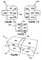
- FIGURE 1 is a plan view of a blank for forming a modular box with an access structure according to a first embodiment of the invention;
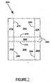
- FIGURE 2 is a plan view of a blank for forming an outer cover to be used with the blank of Figure 1;
- FIGURES 3A and 3B illustrate two modular boxes formed from the blank of Figure 1;
- FIGURE 4 illustrates the outer cover blank shown in Figure 2;
- FIGURE 5 is a perspective view of the divisible carton formed from the blanks illustrated in Figures 3A, 3B and 4;
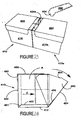
- FIGURE 6 is a perspective view of the divisible carton showing the modular boxes separated;
- FIGURES 7 and 8 illustrate the opening of the access structure of one of the modular boxes shown in Figure 6;
- FIGURE 9 is a plan view of a blank for forming an open top modular box according to a second embodiment of the invention;
- FIGURE 10 is a plan view of a blank for forming an outer cover for use with the blank illustrated in Figure 9;
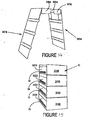
- FIGURES 11, 12, 13 and 14 illustrate the construction of the outer cover from the blank illustrated in Figure 10;
- FIGURE 15 is a perspective view of a plurality of open top modular boxes stacked in a vertical arrangement ready to receive the outer cover shown in Figure 14;
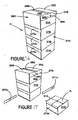
- FIGURE 16 is a perspective view of the divisible carton in a set up and loaded condition;
- FIGURE 17 is a perspective view of the separation of an open top modular box from the divisible carton of Figure 16;
- FIGURE 18 is a plan view of a blank for forming a modular box according to a third embodiment of the invention;
- FIGURE 19 is a plan view of a blank for forming an outer cover to be used with the blank illustrated in Figure 18;
- FIGURES 20A, 20B, 21 and 22 illustrate the construction of the divisible carton from the blanks of Figures 18 and 19; and
- FIGURES 23 and 24 illustrate the separation of the divisible carton of Figure 22 and the opening of an access structure.
-
- Referring to the drawings there is shown several embodiments of carton and blanks for forming the carton. The blanks and carton are formed from paperboard or other suitable foldable sheet material, that has been cut and fold lines added. The carton is used to hold a plurality of articles, for example, washing powder tablets or the like, and to dispense the article. The invention also provides a divisible carton for multiple packaging. Whilst in the illustrated embodiments, a unitary blank is used to make a single carton, it is envisaged that two or more blanks may be employed, for example to provide the
access structure 456 described in more detail below. - Referring now to Figure 1, there is shown a blank for forming part of a divisible carton. Reference is made to the drawings and in particular Figures 1 to 24. There is shown various embodiments of modular carton and blanks for forming an open top modular box. Turning to the first embodiment of Figures 1 and 2, there is shown a blank for forming a top cover formed from like material. Whilst in this embodiment, a two part blank is employed; it is envisaged that the modular boxes could be constructed from a unitary blank without departing from the scope of invention.
- Referring to Figure 1, the blank 210 comprises in series a first
side wall panel 214, abase 212 and a secondside wall panel 216 hinged together alongfold lines end wall panel 222 hinged to a first lateral edge ofbase panel 212 alongfold line 226. Along the opposite lateral edge, there is provided aclosure panel 224 which is hinged thereto alongfold line 228. Theclosure panel 224 forms part of theaccess structure 238, described in more detail below. - In order to secure the side and end wall panels together, there is provided a plurality of securing
flaps side wall panels fold lines securing flap 223 for securingend wall panel 222 to the outer cover OC (Figure 2) may be hinged toend wall panel 222 alongfold line 225. - The
access structure 238 is provided to gain access to the interior of the carton to retrieve articles contained therein. In this embodiment, there comprises a dispensing drawer which is provided by theswingable closure panel 224 hinged to one of the outer panels of the carton, for examplebase wall panel 212 alongfold line 228. There further comprises one or more wing flaps 240, 242 which in this embodiment are provided on each side of theclosure panel 224. Wing flaps 240, 242 are hinged toclosure panel 224 alongfold lines respective closure panel 224. There may further comprise one ormore anchor elements closure panel 224 in a closed position. Preferably, the stopper and or anchor elements protrude from the upper edge of the respective wing flaps 240 and 242. It will be seen from Figure 1 that, in this embodiment, wing flaps 240 and 242 are separated from adjacent panels forming the side wall bycut lines - Turning to the blank 260 for forming the outer cover, there comprises a first
top panel 262 and a secondtop panel 268 which are connected together by a frangible connectingportion 266.Portion 266 is secured to the firsttop panel 262 alongfrangible line 270 and to the secondtop cover 268 byfrangible line 272. Along each longitudinal edge of the first and secondtop panels flaps flaps first cover panel 262 alongfold lines flaps top panel 268 alongfold lines - The frangible connecting
portion 266 may be provided with apull tab 264 to assist in removing the frangible portion from the divisible carton. - Turning to the construction of the divisible carton illustrated in Figures 3 and 5, it is envisaged that the carton of the present invention can be formed by a series of sequential folding and gluing operations to be performed in a straight line machine, so that the carton is not required to be rotated or inverted to complete its construction. The folding and construction process is not limited to that described below and can be altered according to particular manufacturing requirements.
- Referring to Figures 3A and 3B, the modular boxes C are constructed first from a pair of
blanks - The
access structure 238 is formed by inwardly folding flaps 240 and 242 alongfold lines Closure panel 224 is then folded towardsbase panel 212 alongfold llines 228. Thereafterside panels fold lines wing flaps - Securing
flaps fold lines end wall panel 222 which is folded inwardly along fold lines 226. Securingflaps panel 222 by glue or other suitable means known in the art. - Thus a modular box B is in a set up condition and is brought into contact with a second
modular box B 1 formed from a blank 10B whereby thecover panels closure panels - The articles are loaded into the carton by relative vertical movement between the carton and articles during continuous forward feed, as is well known and the
outer cover 260 is then applied to complete construction of the carton C, as illustrated in Figure 5. To secure the outer cover to themodular boxes panels fold line side walls modular boxes frangible panel 266 from the carton by tearing alongfrangible lines - To assist the user, a
pull tab 264 is provided on thefrangible connection panel 266. Each modular box can then be separated. In order to gain access to the interior of the carton, theaccess structure 238 is used. More particularly, theaccess structure 238 provides temporary access to the interior of the carton by creating an opening in one of the end walls. The user pulls on theclosure panel 224 to cause it to pivot aboutfold line 228, shown in Figure 8.Engaging elements cover panel 268 to preventclosure panel 224 from inadvertently opening beyond a predetermined angle. - To recluse the
access structure 238, theclosure 224 is pushed inwardly andengaging elements cover panel 268. - Turning to the second embodiment of divisible carton illustrated in Figures 9 to 17, there is shown a plurality of open top modular boxes arranged in a substantially vertical arrangement one above the other and connected together by means of an outer cover. The cartons are formed from
blanks - Turning to the construction of a modular box from the blank 310, there comprises in series a first
side wall panel 314, abase 312 and a secondside wall panel 316 hinged together alongfold lines end wall panels base panel 312 alongfold lines - In order to secure the side and end wall panels together, there is provided a plurality of securing
flaps wall panels fold lines - In this embodiment, there comprises two or more modular boxes that are identical or substantially similar to the type hereinbefore described and illustrated in figure 9 and therefore shall not be described in any greater detail.
- The outer cover is constructed from blank 360.
- The blank 360 comprises a first
top panel 362 and a secondtop panel 368 which are connected together by a frangible connectingportion 366.Portion 366 is secured to firsttop panel 362 alongfrangible line 370 and to secondtop cover panel 368 byfrangible line 372. The frangible connectingportion 366 may be provided with apull tab 364 to assist in removing the frangible portion from the divisible cartons. - Outer end wall panels are provided along each side of the top cover panels therefore, along one side of
top cover panel 368 there is providedend panel 369 which corresponds in number to the number of modular boxes to be used. In the embodiment illustrated in Figure 10, there comprises four outerend wall panels part - In one class of embodiments there comprises a protruding element which functions as a pull tab to assist in removing the
frangible parts 371, described in more detail. Along the opposing side edge oftop cover 362 there comprises similar outerend wall panels 373a to 373d that are separated by frangible connectingportions - In one class of embodiments, there further comprises a retention structure for retaining the modular boxes to avoid inadvertent removal. It will be seen from Figure 10 that the retention structure may be formed on the opposing longitudinal edges of top cover panels and, optionally, the upper most outer
end wall panels pull tab 366. - Gusset arrangements are provided to connect the side retention panels to the outer
end wall panels side retention panel 382 is hinged totop cover panel 368 alongfold line 386 and gusset structure is provided bygusset panels edge panel 382 alongfold line 367 and to endretention wall panel 369a along an extension offold line 386. Afold line 383bhingedly interconnects panels line 379b. - Similarly,
side retention panel 376 is hinged totop cover panel 362 alongfold line 380 and gusset structure is provided by a pair ofgusset panels respective fold line 363.Panel 381a is hinged to side wall panel 378 along one extension offold line 363 andgusset panel 377a is hinged to endcover panel 373a by an extension offold line 380. On the opposing longitudinal ofcover panels side cover panel 384 which is hinged thereto alongfold line 388. In this embodiment, gusset structures are provided along each lateral edge and is substantially identical to gusset panels described in the preceding paragraph and are not therefore described in any greater detail. - In order to construct the outer cover and modular boxes, it is envisaged that the divisible carton of the present invention can be formed by a series of sequential folding and gluing operations performed in a straight line machine so that the divisible carton is not required to be rotated or inverted to complete its construction.
- The modular boxes are constructed by folding
side panels end panel base panel 312 alongfold lines - The construction of the outer cover will be described by reference to Figures 11, 12, 13 and 14. The first step is for the retention structures to be formed whereby
gusset panels outer end panels side cover panels fold lines 379 and 386; 388 and 380. Thus, the outer cover panel is in a flat collapsed position in Figure 12. - The
side retention panels top cover panel end cover panels fold lines fold lines fold lines top cover panels - The outer cover is then applied to the open top modular boxes that are stacked in a vertical arrangement, one above the other, and the
end panels end cover panels - Thus the carton C is in a set up and loaded condition as illustrated in Figure 16.
- In order to gain access to the interior of the divisible carton, it is necessary to separate the modular boxes. This is achieved by removing the
frangible panels side panels - Turning to the third embodiment illustrated in figures 18 to 24, there comprises a pair of
blanks blanks - In this embodiment there comprises an
access structure 456 to gain access to the interior of the carton to retrieve articles contained therein. Theaccess structure 456 comprises an article feeder. The article feeder is provided with a platform upon which the articles are placed. The platform is connected to theclosure panel 424 and is moveable within the carton. In Figure 18, the platform is provided by abase end panel 452, aplatform panel 453 and securing means 455 for securing theplatform panel 453 to theclosure panel 424. The base end orspacer panel 452 is connected tobase panel 412 alongfold line 457 and aplatform panel 453 is hinged tospacer panel 452 alongfold line 458. The securing means is, in this embodiment, provided by a securingflap 455 which is hinged to the opposing end edge ofplatform panel 453 alongfold line 459. - Turning to the construction of the divisible carton illustrated in Figures 18 to 24, it is envisaged that the carton of the present invention can be formed by a series of sequential folding and gluing operations to be performed in a straight line machine, so that the carton is not required to be rotated or inverted to complete its construction. The folding and construction process is not limited to that described below and can be altered according to particular manufacturing requirements.
- Referring to Figures 20A to 22, the platform is constructed first, whereby
spacer panel 452,platform panel 453 and securingflap 455 are folded aboutfold line 457 and into face contacting arrangement withbase panel 412 andaccess closure panel 424. Securingflap 455 is secured toclosure panel 424 by suitable securing means, for example glue G or other means known in the art.Side panel 416 and the associatedend wall panel 422 are folded in an upward direction alongfold line 420 and endwall panel 422 is folded out of alignment withside wall panel 416 alongfold line 426, so as to close the rear of the carton. Theother side wall 414 is folded about fold line 448 and securingflap 430 adhered to the inside face ofend wall 422. - The
access structure 456 is formed by inwardly folding wing flaps 440 and 442 alongfold lines Closure panel 424 is then folded aboutfold line 428, to close the front of the carton. It will be seen that the folding action ofclosure panel 424 causes theplatform panel 453 to be folded out of alignment withspacer panel 452. Thus the article feeder andaccess structure 456 are placed in the set up condition. - The articles are loaded into the carton C by a relative vertical movement between the carton and the articles during continuous forward feed, as is well known.
- The construction of the other divisible carton from the blank 410a is substantially identical to that described. The two cartons are then aligned so that their
cover 460 is secured to the two cartons. - When the end user wants to gain access to the interior of the carton, the frangible connecting
panel 466 is removed from the outer cover as shown in Figure 23 and theaccess structure 456 is used. - The carton in Figure 3 is supplied to an end user. In order to gain access to the interior of the carton, the
access structure 456 is used. More particular, theaccess structure 456 provides temporary access to the interior of the carton by creating an opening in one of the end walls. In order to move theclosure panel 424/424a from a closed position to an open position, the user can pull on theclosure panel fold line 428 shown in Figure 24.Closure panel wing panels outer cover closure panel - To reclose the
access structure 456, theclosure panel engaging elements outer cover closure panel - It will be seen from Figure 24 that the article feeder operates when the
closure panel 424 is moved between closed and open positions. Thus, theplatform panel 424 is moveable in a forward and backward direction so that an article A onplatform panel 453 will be moved forward with respect to other articles contained in the carton thereby allowing easier access to remove it from the carton. In order to assist the forward movement an additional pusher element may be used to abut a rear portion of an article. The pusher element may be pivoted aboutfold line 457 during the forward movement of the closure panel to push the contents of the carton forward. - It will be recognised that as used herein, directional references such as "top", "base", "end", "side", "lateral", "longitudinal", "upper" and "lower" do not limit the respective panels to such orientation, but merely serve to distinguish these panels one from another. Any reference to hinged connection should not be construed as necessarily referring to a single fold line only: indeed it is envisaged that hinged connection can be formed from one or more of one of the following, a score line, a frangible line or a fold line, without departing from the scope of invention.
- The present invention and its preferred embodiment relates to an article carrier that is shaped to provide satisfactory strength to hold articles securely, but with a degree of flexibility so that during transit the articles are retained within the carrier. The shape of the blank minimises the amount of paperboard required and the carrier can be applied to one or more articles by hand or automatic machinery. It is anticipated that the invention can be applied to a variety of carriers and is not limited to those of the fully enclosed type hereinabove described. Further or alternatively, the carton may be adapted to carry a greater number of articles without departing from the scope of the invention.
- The following are not claims but statements about the invention:-
- A carton for accommodating one or more articles which carton is provided with an access structure for the removal of articles from within the carton, the access structure comprising a closure panel hinged to a carton wall for forward and backward pivotal movement and a moveable platform hinged to the closure panel for moving the contents of the carton forward for their removal in response to the forward pivotal movement of the closure panel.
- The carton wherein the platform comprises a platform panel adapted to move forwardly to present the articles thereon for removal as the closure panel is swung open to a dispensing position.
- A carton wherein the movable platform is hinged to the closure panel along a fold line spaced above lower edge of the closure panel.
- A carton wherein the platform is spaced from the base of the carton by a spacer panel.
- A carton for accommodating one or more articles, which carton comprising a closure panel hinged at its lower edge to a carton wall for forward and backward pivotal movement, and a pusher element linked to the closure panel to push an article held within the carton forward in response to forward movement of the closure panel.
- The carton wherein the pusher element is hinged at its lower edge to the carton wall.
- The carton wherein the pusher element is linked to the closure panel by a connecting panel spaced from the carton wall.
- The carton wherein articles held within the carton are placed upon the connecting panel.
- A carton for accommodating a plurality of articles, which carton having a dispensing drawer comprising a closure panel hinged to a carton wall for movement between open dispensing position and a closed position and at least one wing flap hinged to the closure panel and extending into the carton for movement along with the closure panel wherein the one wing flap has an anchoring element for engaging with a carton wall to retain the closure panel in a closed position.
- The carton wherein at least one wing flap further comprises a stopper element spaced from the anchoring element which stopper element limits the outward movement of the closure panel.
- The carton wherein the anchoring element and/or the stopper element comprises a protrusion positioned on an upper edge of at least one wing flap.
- A blank for forming a carton for accommodating one or more articles the blank comprising a plurality of wall panels for forming a base, a top and opposed side and end walls, and an access structure comprising a closure panel hinged to a first wall panel for forward and backward pivotal movement in a set up condition and panels for forming a moveable platform comprising a spacer panel, a platform panel and a securing flap for securing the platform to the closure panel.
- A blank for forming a carton for accommodating one or more articles, which blank comprising a plurality of wall panels hingedly connected together for forming a top, a base and opposed side and end walls and a closure panel hinged at its lower edge to a first wall panel for forward and backward pivotal movement in a set up condition, wherein there further comprises a pusher element hinged at its lower edge to the first wall panel and a linkage panel is hingedly connected to an intermediate portion of the pusher element and a securing flap connected to the linkage panel for securing to the closure panel.
- A blank for forming a carton for accommodating a plurality of articles, for example washing powder tablets, which blank has a dispensing drawer comprising a swingable closure panel hinged to a wall panel and at least one wing flap hinged to the closure panel, the at least one wing flap has an anchoring element for engaging with an adjacent wall panel to retain the closure panel in a closed position when the carton is in a set up condition.
- The blank wherein at least one wing flap further comprises a stopper element spaced from the anchoring element which stopper element limits the outward movement of the closure panel when the carton is in a set up condition.
- The blank wherein the anchoring element and/or the stopper element comprises a protrusion positioned on an upper edge of at least one wing flap.
- A divisible carton comprising two or more modular boxes for packaging articles, such as tablets for example, each modular box having a structure to access the box interior and a common outer upper cover arranged so as to secure the boxes together and wherein a tear strip is provided so as to permit the boxes to be separated.
- A carton wherein the boxes are secured together such that the access structures are placed in a mutually opposed relationship to prevent access until one box is separated from the other part of the carton.
- A divisible carton wherein the access structure comprises a swingable closure panel.
- A divisible carton comprising two or more open top modular boxes arranged vertically and interconnected by means of a over secured to the side edges of each box, each box having end panels of greater vertical height in relation to the side panels, and wherein tear strips are located on the cover adjacent to each box interface such that the upper edge thereof is located at an elevation equal to or higher than the elevation of the adjacent box bottom to enable each box, when separated, to be reclosed by the upper adjoining box.
- A carton wherein the lower edge of each strip is at a lower elevation than the adjacent box bottom.
- A carton wherein an upper portion of the cover further extends over the top of the uppermost box.
- A carton wherein a further tear strip extends across the upper cover portion to enable access to the interior of the uppermost box.
- A three part blank for forming a divisible carton comprising first and second blanks having a base, side and end panels for forming open topped boxes and a third blank for forming a top cover structure to be secured to the boxes and having a tear strip so as to enable box separation, wherein each box is provided with an access structure.
- A three part blank for forming a divisible carton comprising first and second blanks having base, side and end panels for forming open topped boxes and a third blank for forming a cover structure having tear strips provided therein at box interface positions when secured to the sides of the open topped boxes wherein the end panels of the box blanks have a greater vertical height than the side panels of the box blanks.
Claims (12)
- A divisible carton comprising two or more modular parts for packaging articles and each modular part comprises a series of panels for forming the walls of that modular part, each modular part also has an access means for accessing the articles contained within each modular part, the divisible carton comprising an outer cover arranged so as to secure the modular parts together, the outer cover including at least one opening means, wherein at least one of the opening means is disposed in alignment with the access means of one of the modular parts, such that by deploying that opening means, said access means is exposed so that access can be gained to the articles contained within that modular part.
- A divisible carton according to claim 1 wherein the access means of each modular part comprises a closure panel hinged to one of said walls for forward and backward pivotal movement to open and close an access aperture.
- A divisible carton according to claim 2 wherein the access means of each modular part further comprises a moveable platform mounted within each modular part and hinged to the closure panel for movement therewith, which platform supports the articles contained within each modular part when the closure panel is in the closed position and which closure panel is moved towards the access aperture to move the contents of the modular part forward for their removal in response to the forward pivotal movement of the closure panel.
- A divisible carton comprising two or more modular parts for packaging articles, such as tablets for example, each modular part having access means for removing articles from that modular part, the carton has a common outer cover arranged so as to secure the modular parts together and a tear strip which can be removed to permit the modular parts to be separated, the modular parts are secured together such that the access means of each modular part is oriented to prevent that access means from being operable until one of the modular parts is separated from the next adjacent modular part by removing a tear strip.
- A divisible carton according to claim 4 wherein the access means comprises a swingable closure panel.
- A divisible carton comprising two or more open top modular parts arranged vertically and interconnected by means of an outer cover secured to the side edges of each modular part, each modular part having end panels of greater vertical height in relation to the side panels, and wherein tear strips are located on the cover adjacent to each modular part interface such that the upper edge thereof is located at an elevation equal to or higher than the elevation of the adjacent modular part bottom to enable each modular part, when separated, to be reclosed by the upper adjoining modular part.
- A carton as claimed in claim 6 wherein the lower edge of each tear strip is at a lower elevation than the bottom wall of the adjacent modular part.
- A carton according to claim 6 or claim 7 wherein an upper portion of the outer cover further extends over the top of the uppermost modular part.
- A carton according to claim 8 wherein a further tear strip extends across the upper cover portion to enable access to the interior of the uppermost modular part.
- A three part blank for forming a divisible carton comprising first and second blanks having base, side and end panels for forming open topped modular parts for packaging articles and a third blank for forming an outer cover to be secured to the modular parts, the outer cover has a tear strip which can be removed to permit the modular parts to be separated, wherein at least one of the modular parts is provided with an access means for removing articles from that modular part and wherein the or each access means is oriented when the divisible carton is set up to prevent each access means from being operable until one of the modular parts is separated from the other remaining modular parts.
- A three part blank for forming a divisible carton comprising first and second blanks having base side and end panels for forming open topped boxes and a third blank for forming a cover structure having tear strips provided therein at box interface positions when secured to the sides of the open topped boxes wherein the end panels of the box blanks have a greater vertical height than the side panels of the box blanks.
- A divisible carton according to any of the preceding claims 4-11 wherein the or each access means comprises a closure panel hinged to a wall of the associated modular part for forward and backward pivotal movement to open and close an access aperture, the or each access means comprises a moveable platform mounted within the box and hinged to the closure panel for movement therewith, which platform supports the articles contained within the or each modular part when the closure panel is in the closed position and which closure panel is moved towards the access aperture to move the contents of the modular part forward for their removal in response to the forward pivotal movement of the closure panel.
Applications Claiming Priority (3)
| Application Number | Priority Date | Filing Date | Title |
|---|---|---|---|
| GB0025100 | 2000-10-13 | ||
| GB0025100A GB0025100D0 (en) | 2000-10-13 | 2000-10-13 | Carton and carton blank |
| EP01981493A EP1326779B1 (en) | 2000-10-13 | 2001-10-12 | Carton and carton blank |
Related Parent Applications (1)
| Application Number | Title | Priority Date | Filing Date |
|---|---|---|---|
| EP01981493A Division EP1326779B1 (en) | 2000-10-13 | 2001-10-12 | Carton and carton blank |
Publications (2)
| Publication Number | Publication Date |
|---|---|
| EP1533239A2 true EP1533239A2 (en) | 2005-05-25 |
| EP1533239A3 EP1533239A3 (en) | 2006-04-05 |
Family
ID=9901205
Family Applications (1)
| Application Number | Title | Priority Date | Filing Date |
|---|---|---|---|
| EP05003503A Withdrawn EP1533239A3 (en) | 2000-10-13 | 2001-10-12 | Carton and carton blank |
Country Status (2)
| Country | Link |
|---|---|
| EP (1) | EP1533239A3 (en) |
| GB (1) | GB0025100D0 (en) |
Cited By (4)
| Publication number | Priority date | Publication date | Assignee | Title |
|---|---|---|---|---|
| EP2221254A1 (en) * | 2009-02-23 | 2010-08-25 | MeadWestvaco Corporation | Composite package |
| US8851292B2 (en) | 2010-06-25 | 2014-10-07 | The Procter & Gamble Company | Packaging system for shipping, storing, displaying, and/or dispensing absorbent articles |
| US9604768B2 (en) | 2013-06-19 | 2017-03-28 | Westrock Packaging Systems, Llc | Carton and carton blank |
| IT202100024008A1 (en) * | 2021-09-17 | 2023-03-17 | Vimar Spa | PACKAGE FOR ELECTRICAL MODULES |
Citations (1)
| Publication number | Priority date | Publication date | Assignee | Title |
|---|---|---|---|---|
| US5853088A (en) | 1994-12-02 | 1998-12-29 | The Mead Corporation | Carton |
Family Cites Families (7)
| Publication number | Priority date | Publication date | Assignee | Title |
|---|---|---|---|---|
| US3168234A (en) * | 1963-06-20 | 1965-02-02 | Fred H Bartz | Divisible food carton |
| US3253765A (en) * | 1964-08-04 | 1966-05-31 | Owens Illinois Glass Co | Separable plural container |
| US4377237A (en) * | 1981-03-10 | 1983-03-22 | James River-Dixie/Northern, Inc. | Multiple compartment carton |
| US4533052A (en) * | 1984-02-27 | 1985-08-06 | Owens-Illinois, Inc. | Dual carton |
| US4919269A (en) * | 1988-11-18 | 1990-04-24 | The Mead Corporation | Multiple compartment container |
| US5048690A (en) * | 1989-08-30 | 1991-09-17 | Revlon, Inc. | Carton and blank for making same |
| US6006982A (en) * | 1998-05-04 | 1999-12-28 | Pacific Southwest Container | Dual package container formed from single-piece blank |
-
2000
- 2000-10-13 GB GB0025100A patent/GB0025100D0/en not_active Ceased
-
2001
- 2001-10-12 EP EP05003503A patent/EP1533239A3/en not_active Withdrawn
Patent Citations (1)
| Publication number | Priority date | Publication date | Assignee | Title |
|---|---|---|---|---|
| US5853088A (en) | 1994-12-02 | 1998-12-29 | The Mead Corporation | Carton |
Cited By (5)
| Publication number | Priority date | Publication date | Assignee | Title |
|---|---|---|---|---|
| EP2221254A1 (en) * | 2009-02-23 | 2010-08-25 | MeadWestvaco Corporation | Composite package |
| US8851292B2 (en) | 2010-06-25 | 2014-10-07 | The Procter & Gamble Company | Packaging system for shipping, storing, displaying, and/or dispensing absorbent articles |
| US9604768B2 (en) | 2013-06-19 | 2017-03-28 | Westrock Packaging Systems, Llc | Carton and carton blank |
| IT202100024008A1 (en) * | 2021-09-17 | 2023-03-17 | Vimar Spa | PACKAGE FOR ELECTRICAL MODULES |
| WO2023042169A1 (en) * | 2021-09-17 | 2023-03-23 | Vimar S.P.A. | Packaging for electric modules |
Also Published As
| Publication number | Publication date |
|---|---|
| EP1533239A3 (en) | 2006-04-05 |
| GB0025100D0 (en) | 2000-11-29 |
Similar Documents
| Publication | Publication Date | Title |
|---|---|---|
| US6923365B2 (en) | Carton and carton blank | |
| US6676013B2 (en) | Carton and carton blank | |
| US7000824B2 (en) | Carton and carton blank therefor | |
| EP1725462B1 (en) | Fully enclosed pack with interlocking separator pad and dispenser | |
| US4317536A (en) | Two-piece container | |
| RU2277061C2 (en) | Cardboard box with distribution device | |
| EP0541385A1 (en) | Carton with braced article separating structures | |
| MXPA03008840A (en) | BOX OF CARTON AND TEMPLATE. | |
| EP1218247B1 (en) | Carton and carton blank | |
| CA2386594C (en) | Carton and carton blank | |
| US4151946A (en) | Dispenser container | |
| CA2433318C (en) | Carton and carton blank | |
| US20010037952A1 (en) | Carton and carton blank | |
| EP1456088B1 (en) | Carton and carton blank | |
| EP1378456B1 (en) | Carton and carton blank | |
| CA2429513C (en) | Carton and carton blank therefor | |
| EP1353855B1 (en) | Carton and carton blank | |
| EP1615829B1 (en) | Fully enclosed carton and blank | |
| EP1456090B1 (en) | Carton and carton blank | |
| US4043095A (en) | Method of packaging in carrier with drop down partition | |
| CA2380773C (en) | Carton and carton blank | |
| EP1456089B1 (en) | Protective box for fragile articles | |
| EP1375359A1 (en) | Carton and carton blank | |
| WO2006047736A2 (en) | Dispensing carton |
Legal Events
| Date | Code | Title | Description |
|---|---|---|---|
| PUAI | Public reference made under article 153(3) epc to a published international application that has entered the european phase |
Free format text: ORIGINAL CODE: 0009012 |
|
| 17P | Request for examination filed |
Effective date: 20050218 |
|
| AC | Divisional application: reference to earlier application |
Ref document number: 1326779 Country of ref document: EP Kind code of ref document: P |
|
| AK | Designated contracting states |
Kind code of ref document: A2 Designated state(s): AT BE CH CY DE DK ES FI FR GB GR IE IT LI LU MC NL PT SE TR |
|
| PUAL | Search report despatched |
Free format text: ORIGINAL CODE: 0009013 |
|
| AK | Designated contracting states |
Kind code of ref document: A3 Designated state(s): AT BE CH CY DE DK ES FI FR GB GR IE IT LI LU MC NL PT SE TR |
|
| AKX | Designation fees paid |
Designated state(s): AT BE CH CY DE DK ES FI FR GB GR IE IT LI LU MC NL PT SE TR |
|
| RAP1 | Party data changed (applicant data changed or rights of an application transferred) |
Owner name: MEADWESTVACO PACKAGING SYSTEMS LLC |
|
| 17Q | First examination report despatched |
Effective date: 20070906 |
|
| GRAP | Despatch of communication of intention to grant a patent |
Free format text: ORIGINAL CODE: EPIDOSNIGR1 |
|
| STAA | Information on the status of an ep patent application or granted ep patent |
Free format text: STATUS: THE APPLICATION IS DEEMED TO BE WITHDRAWN |
|
| 18D | Application deemed to be withdrawn |
Effective date: 20090820 |