EP1533173A2 - Fuel cell vehicle - Google Patents
Fuel cell vehicle Download PDFInfo
- Publication number
- EP1533173A2 EP1533173A2 EP04026582A EP04026582A EP1533173A2 EP 1533173 A2 EP1533173 A2 EP 1533173A2 EP 04026582 A EP04026582 A EP 04026582A EP 04026582 A EP04026582 A EP 04026582A EP 1533173 A2 EP1533173 A2 EP 1533173A2
- Authority
- EP
- European Patent Office
- Prior art keywords
- fuel
- gas
- fuel cell
- vehicle body
- discharge port
- Prior art date
- Legal status (The legal status is an assumption and is not a legal conclusion. Google has not performed a legal analysis and makes no representation as to the accuracy of the status listed.)
- Granted
Links
Images







Classifications
-
- H—ELECTRICITY
- H01—ELECTRIC ELEMENTS
- H01M—PROCESSES OR MEANS, e.g. BATTERIES, FOR THE DIRECT CONVERSION OF CHEMICAL ENERGY INTO ELECTRICAL ENERGY
- H01M16/00—Structural combinations of different types of electrochemical generators
- H01M16/003—Structural combinations of different types of electrochemical generators of fuel cells with other electrochemical devices, e.g. capacitors, electrolysers
- H01M16/006—Structural combinations of different types of electrochemical generators of fuel cells with other electrochemical devices, e.g. capacitors, electrolysers of fuel cells with rechargeable batteries
-
- B—PERFORMING OPERATIONS; TRANSPORTING
- B60—VEHICLES IN GENERAL
- B60K—ARRANGEMENT OR MOUNTING OF PROPULSION UNITS OR OF TRANSMISSIONS IN VEHICLES; ARRANGEMENT OR MOUNTING OF PLURAL DIVERSE PRIME-MOVERS IN VEHICLES; AUXILIARY DRIVES FOR VEHICLES; INSTRUMENTATION OR DASHBOARDS FOR VEHICLES; ARRANGEMENTS IN CONNECTION WITH COOLING, AIR INTAKE, GAS EXHAUST OR FUEL SUPPLY OF PROPULSION UNITS IN VEHICLES
- B60K1/00—Arrangement or mounting of electrical propulsion units
-
- B—PERFORMING OPERATIONS; TRANSPORTING
- B60—VEHICLES IN GENERAL
- B60K—ARRANGEMENT OR MOUNTING OF PROPULSION UNITS OR OF TRANSMISSIONS IN VEHICLES; ARRANGEMENT OR MOUNTING OF PLURAL DIVERSE PRIME-MOVERS IN VEHICLES; AUXILIARY DRIVES FOR VEHICLES; INSTRUMENTATION OR DASHBOARDS FOR VEHICLES; ARRANGEMENTS IN CONNECTION WITH COOLING, AIR INTAKE, GAS EXHAUST OR FUEL SUPPLY OF PROPULSION UNITS IN VEHICLES
- B60K15/00—Arrangement in connection with fuel supply of combustion engines or other fuel consuming energy converters, e.g. fuel cells; Mounting or construction of fuel tanks
- B60K15/03—Fuel tanks
- B60K15/063—Arrangement of tanks
- B60K15/067—Mounting of tanks
- B60K15/07—Mounting of tanks of gas tanks
-
- B—PERFORMING OPERATIONS; TRANSPORTING
- B60—VEHICLES IN GENERAL
- B60L—PROPULSION OF ELECTRICALLY-PROPELLED VEHICLES; SUPPLYING ELECTRIC POWER FOR AUXILIARY EQUIPMENT OF ELECTRICALLY-PROPELLED VEHICLES; ELECTRODYNAMIC BRAKE SYSTEMS FOR VEHICLES IN GENERAL; MAGNETIC SUSPENSION OR LEVITATION FOR VEHICLES; MONITORING OPERATING VARIABLES OF ELECTRICALLY-PROPELLED VEHICLES; ELECTRIC SAFETY DEVICES FOR ELECTRICALLY-PROPELLED VEHICLES
- B60L58/00—Methods or circuit arrangements for monitoring or controlling batteries or fuel cells, specially adapted for electric vehicles
- B60L58/30—Methods or circuit arrangements for monitoring or controlling batteries or fuel cells, specially adapted for electric vehicles for monitoring or controlling fuel cells
- B60L58/32—Methods or circuit arrangements for monitoring or controlling batteries or fuel cells, specially adapted for electric vehicles for monitoring or controlling fuel cells for controlling the temperature of fuel cells, e.g. by controlling the electric load
- B60L58/33—Methods or circuit arrangements for monitoring or controlling batteries or fuel cells, specially adapted for electric vehicles for monitoring or controlling fuel cells for controlling the temperature of fuel cells, e.g. by controlling the electric load by cooling
-
- B—PERFORMING OPERATIONS; TRANSPORTING
- B60—VEHICLES IN GENERAL
- B60L—PROPULSION OF ELECTRICALLY-PROPELLED VEHICLES; SUPPLYING ELECTRIC POWER FOR AUXILIARY EQUIPMENT OF ELECTRICALLY-PROPELLED VEHICLES; ELECTRODYNAMIC BRAKE SYSTEMS FOR VEHICLES IN GENERAL; MAGNETIC SUSPENSION OR LEVITATION FOR VEHICLES; MONITORING OPERATING VARIABLES OF ELECTRICALLY-PROPELLED VEHICLES; ELECTRIC SAFETY DEVICES FOR ELECTRICALLY-PROPELLED VEHICLES
- B60L58/00—Methods or circuit arrangements for monitoring or controlling batteries or fuel cells, specially adapted for electric vehicles
- B60L58/40—Methods or circuit arrangements for monitoring or controlling batteries or fuel cells, specially adapted for electric vehicles for controlling a combination of batteries and fuel cells
-
- B—PERFORMING OPERATIONS; TRANSPORTING
- B62—LAND VEHICLES FOR TRAVELLING OTHERWISE THAN ON RAILS
- B62M—RIDER PROPULSION OF WHEELED VEHICLES OR SLEDGES; POWERED PROPULSION OF SLEDGES OR SINGLE-TRACK CYCLES; TRANSMISSIONS SPECIALLY ADAPTED FOR SUCH VEHICLES
- B62M7/00—Motorcycles characterised by position of motor or engine
-
- B—PERFORMING OPERATIONS; TRANSPORTING
- B60—VEHICLES IN GENERAL
- B60L—PROPULSION OF ELECTRICALLY-PROPELLED VEHICLES; SUPPLYING ELECTRIC POWER FOR AUXILIARY EQUIPMENT OF ELECTRICALLY-PROPELLED VEHICLES; ELECTRODYNAMIC BRAKE SYSTEMS FOR VEHICLES IN GENERAL; MAGNETIC SUSPENSION OR LEVITATION FOR VEHICLES; MONITORING OPERATING VARIABLES OF ELECTRICALLY-PROPELLED VEHICLES; ELECTRIC SAFETY DEVICES FOR ELECTRICALLY-PROPELLED VEHICLES
- B60L2200/00—Type of vehicles
- B60L2200/12—Bikes
-
- B—PERFORMING OPERATIONS; TRANSPORTING
- B60—VEHICLES IN GENERAL
- B60Y—INDEXING SCHEME RELATING TO ASPECTS CROSS-CUTTING VEHICLE TECHNOLOGY
- B60Y2200/00—Type of vehicle
- B60Y2200/10—Road Vehicles
- B60Y2200/12—Motorcycles, Trikes; Quads; Scooters
-
- B—PERFORMING OPERATIONS; TRANSPORTING
- B62—LAND VEHICLES FOR TRAVELLING OTHERWISE THAN ON RAILS
- B62K—CYCLES; CYCLE FRAMES; CYCLE STEERING DEVICES; RIDER-OPERATED TERMINAL CONTROLS SPECIALLY ADAPTED FOR CYCLES; CYCLE AXLE SUSPENSIONS; CYCLE SIDECARS, FORECARS, OR THE LIKE
- B62K2202/00—Motorised scooters
-
- B—PERFORMING OPERATIONS; TRANSPORTING
- B62—LAND VEHICLES FOR TRAVELLING OTHERWISE THAN ON RAILS
- B62K—CYCLES; CYCLE FRAMES; CYCLE STEERING DEVICES; RIDER-OPERATED TERMINAL CONTROLS SPECIALLY ADAPTED FOR CYCLES; CYCLE AXLE SUSPENSIONS; CYCLE SIDECARS, FORECARS, OR THE LIKE
- B62K2204/00—Adaptations for driving cycles by electric motor
-
- H—ELECTRICITY
- H01—ELECTRIC ELEMENTS
- H01M—PROCESSES OR MEANS, e.g. BATTERIES, FOR THE DIRECT CONVERSION OF CHEMICAL ENERGY INTO ELECTRICAL ENERGY
- H01M2250/00—Fuel cells for particular applications; Specific features of fuel cell system
- H01M2250/20—Fuel cells in motive systems, e.g. vehicle, ship, plane
-
- Y—GENERAL TAGGING OF NEW TECHNOLOGICAL DEVELOPMENTS; GENERAL TAGGING OF CROSS-SECTIONAL TECHNOLOGIES SPANNING OVER SEVERAL SECTIONS OF THE IPC; TECHNICAL SUBJECTS COVERED BY FORMER USPC CROSS-REFERENCE ART COLLECTIONS [XRACs] AND DIGESTS
- Y02—TECHNOLOGIES OR APPLICATIONS FOR MITIGATION OR ADAPTATION AGAINST CLIMATE CHANGE
- Y02E—REDUCTION OF GREENHOUSE GAS [GHG] EMISSIONS, RELATED TO ENERGY GENERATION, TRANSMISSION OR DISTRIBUTION
- Y02E60/00—Enabling technologies; Technologies with a potential or indirect contribution to GHG emissions mitigation
- Y02E60/10—Energy storage using batteries
-
- Y—GENERAL TAGGING OF NEW TECHNOLOGICAL DEVELOPMENTS; GENERAL TAGGING OF CROSS-SECTIONAL TECHNOLOGIES SPANNING OVER SEVERAL SECTIONS OF THE IPC; TECHNICAL SUBJECTS COVERED BY FORMER USPC CROSS-REFERENCE ART COLLECTIONS [XRACs] AND DIGESTS
- Y02—TECHNOLOGIES OR APPLICATIONS FOR MITIGATION OR ADAPTATION AGAINST CLIMATE CHANGE
- Y02E—REDUCTION OF GREENHOUSE GAS [GHG] EMISSIONS, RELATED TO ENERGY GENERATION, TRANSMISSION OR DISTRIBUTION
- Y02E60/00—Enabling technologies; Technologies with a potential or indirect contribution to GHG emissions mitigation
- Y02E60/30—Hydrogen technology
- Y02E60/50—Fuel cells
-
- Y—GENERAL TAGGING OF NEW TECHNOLOGICAL DEVELOPMENTS; GENERAL TAGGING OF CROSS-SECTIONAL TECHNOLOGIES SPANNING OVER SEVERAL SECTIONS OF THE IPC; TECHNICAL SUBJECTS COVERED BY FORMER USPC CROSS-REFERENCE ART COLLECTIONS [XRACs] AND DIGESTS
- Y02—TECHNOLOGIES OR APPLICATIONS FOR MITIGATION OR ADAPTATION AGAINST CLIMATE CHANGE
- Y02T—CLIMATE CHANGE MITIGATION TECHNOLOGIES RELATED TO TRANSPORTATION
- Y02T10/00—Road transport of goods or passengers
- Y02T10/60—Other road transportation technologies with climate change mitigation effect
- Y02T10/70—Energy storage systems for electromobility, e.g. batteries
-
- Y—GENERAL TAGGING OF NEW TECHNOLOGICAL DEVELOPMENTS; GENERAL TAGGING OF CROSS-SECTIONAL TECHNOLOGIES SPANNING OVER SEVERAL SECTIONS OF THE IPC; TECHNICAL SUBJECTS COVERED BY FORMER USPC CROSS-REFERENCE ART COLLECTIONS [XRACs] AND DIGESTS
- Y02—TECHNOLOGIES OR APPLICATIONS FOR MITIGATION OR ADAPTATION AGAINST CLIMATE CHANGE
- Y02T—CLIMATE CHANGE MITIGATION TECHNOLOGIES RELATED TO TRANSPORTATION
- Y02T90/00—Enabling technologies or technologies with a potential or indirect contribution to GHG emissions mitigation
- Y02T90/40—Application of hydrogen technology to transportation, e.g. using fuel cells
Definitions
- the present invention relates to a fuel cell vehicle which includes a fuel cylinder and a fuel cell stack, and runs by electric power obtained by supplying reactive gas and fuel gas from the fuel cylinder to the fuel cell stack.
- the present invention relates to a fuel cell vehicle suitable for application to, for example, two-wheeled, three-wheeled or four-wheeled vehicles and the like.
- the fuel cylinder mounted on the fuel cell vehicle is filled with high-pressure hydrogen gas.
- a pressure control valve is provided to prevent an internal gas pressure from being a certain gas pressure or more.
- Patent Document 1 Japanese Patent Laid-Open No. 2001-130468 (Fig. 1)
- the pressure control valve when the pressure control valve is actuated to discharge the hydrogen gas to the air from the fuel cylinder, it is preferable that the hydrogen gas is discharged to the air, in other words, to the outside of the vehicle while the discharge pressure is lowered and the fuel gas is diffused.
- the present invention was made in consideration for the foregoing problem. It is an object of the present invention to provide a fuel cell vehicle on which a fuel cylinder is mounted, which is capable of efficiently diffusing fuel gas discharged to the air from the fuel cylinder and discharging the fuel gas to the outside of the vehicle.
- a fuel cell vehicle which includes a fuel cylinder and a fuel cell stack, and runs by electric power obtained by supplying reactive gas and fuel gas from the fuel cylinder to the fuel cell stack, includes: a vehicle body frame which surrounds and supports the fuel cylinder, when planarly viewed; and a gas discharger which is provided in the fuel cylinder, has a gas discharge port and discharges the fuel gas in the fuel cylinder to the air through the gas discharge port.
- the gas discharge port is disposed so as to face the vehicle body frame (the invention according to claim 1).
- the gas discharge port is disposed so as to face the vehicle body frame, the fuel gas discharged from the fuel cylinder can be efficiently diffused and discharged to the outside of the vehicle by allowing the fuel gas to hit against the vehicle body frame.
- the fuel gas can be efficiently diffused by the diffusion guide (the invention according to claim 2).
- a concave part facing the gas discharge port is formed in the diffusion guide, and a plurality of openings through which a part of the fuel gas passes are provided in the concave part. Accordingly, the discharged fuel gas is diffused through the concave part, hits against the vehicle body frame through the openings and is diffused by the vehicle body frame. Thus, the fuel gas can be more efficiently diffused (the invention according to claim 3).
- the fuel cell vehicle of the present invention includes a vehicle body cover which covers the vehicle body frame surrounding and supporting the fuel cylinder.
- an opening for discharging the fuel gas diffused by the vehicle body frame or the diffusion guide to the air outside of the vehicle body cover is provided near the vehicle body frame, against which the fuel gas hits, or the diffusion guide in the vehicle body cover.
- the gas discharger is a pressure control valve which discharges the fuel gas by automatically opening the discharge port when a fuel gas pressure in the fuel cylinder exceeds a predetermined value (the invention according to claim 5).
- a pressure control valve for example, a spring tension and the internal fuel gas pressure is oppositely applied to the valve body, and the pressure control valve has a function of opening the valve body and releasing an excess pressure to the air when the fuel gas pressure exceeds the spring tension.
- the fuel cell vehicle on which the fuel cylinder is mounted by allowing the fuel gas discharged from the fuel cylinder through the gas discharge port of the gas discharger to hit against the vehicle body frame or the diffusion guide, the fuel gas can be efficiently diffused and discharged to the outside of the vehicle.
- FIG. 1 is a partially omitted side view showing a configuration of a fuel cell motorcycle 10 to which an embodiment of a fuel cell vehicle of the present invention is applied.
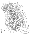
- FIG. 2 is a perspective view of the fuel cell motorcycle 10.
- FIG. 3 is a schematic diagram showing a framework of a vehicle body frame 12 of the fuel cell motorcycle 10.
- FIG. 4 is an explanatory diagram showing a state where the vehicle body frame 12 supports a fuel cylinder 14.
- the vehicle body frame 12 basically includes: a head pipe 16; a pair of left and right upper down frames 18L and 18R which extend obliquely downward from the head pipe 16 as a starting point (one ends); a pair of left and right lower down frames 20L and 20R which extend downward from the head pipe 16 as a starting point (upper ends) below the upper down frames 18L and 18R; a pair of left and right upper frames 22L and 22R which extend obliquely upward from approximately the center of the lower down frames 20L and 20R and have the other ends of the upper down frames 18L and 18R connected in the middle thereof; a pair of left and right lower frames 24L and 24R which extend backward from lower ends of the lower down frames 20L and 20R below the upper frames 22L and 22R; a annular frame 26 which has an approximately square ring-like structure and supports, with its four comers, rear ends of the upper frames 22L and 22R and the lower frames 24L and 24R; and an upper connection frame 30 and
- the vehicle body frame 12 further includes a rear plate 28 which extends obliquely upward from the rear ends of the lower frames 24L and 24R.
- a pair of left and right front forks 34 which support a front wheel FW so as to be rotatable through a bridge 17 are connected to the head pipe 16.
- a steering wheel 36 is connected to the front forks 34 so as to be steerable through the bridge 17.
- a pair of left and right swinging frames 38 are supported so as to be swingable by use of a shaft 40 as a supporting point, and a rear wheel RW as a driving wheel is supported at rear ends of the swinging frames 38.
- a motor (not shown) which is driven by electric power generated in a fuel cell system is integrally included.
- the fuel cell system is included in the fuel cell motorcycle 10.
- This fuel cell system basically includes: a fuel cell stack 42 which generates electricity (currents) by reaction between fuel gas (hydrogen gas) supplied to an anode electrode and reactive gas (oxygen gas) supplied to a cathode electrode; a fuel cell box 44 which has the fuel cell stack 42 built-in; a fuel cylinder (hydrogen cylinder) 14 which stores the fuel gas to be supplied to the fuel cell stack 42 in the fuel cell box 44 in a high pressure state; and a piping system 46 which takes in the outside air (air) to be supplied into the fuel cell box 44 as the reactive gas, scavenging gas and coolant gas.
- the fuel cell system further includes, as auxiliary power, a plurality of secondary batteries 47 and 48 and a fuel cell 49.
- the fuel cylinder 14 is mounted on a front side of a driver seat 52 along the left and right upper frames 22L and 22R so as to be supported by the upper frames 22L and 22R therebetween. Specifically, the fuel cylinder 14 is mounted in a reclined posture in which a valve assembly 50 faces the rear and an end (front end) of the fuel cylinder on the valve assembly 50 is higher than the other end (rear end) thereof.
- valve assembly 50 provided in the fuel cylinder 14 includes: a shut-off valve 54 to which high-pressure hydrogen is supplied in a hydrogen fuel station and the like; a flow regulating valve 56 which regulates a flow rate of the fuel gas supplied to the fuel cell stack 42; and a pressure control valve 58 as a gas discharger having a gas discharge port 59, which is automatically released when an internal gas pressure reaches a certain gas pressure or more.
- the left and right upper frames 22L and 22R are formed in such a manner that a space between the both becomes narrower in a lower portion than an upper portion.
- the fuel cylinder 14 can be supported in the reclined posture.
- a shock absorbing member 45 is attached on contact surfaces of the upper frames 22L and 22R.
- surfaces of the upper frames 22L and 22R, which support the fuel cylinder 14, have an approximately plate shape.
- the fuel cylinder 14 is firmly held by the upper frames 22L and 22R by use of tying metal bands 60 and 62 (see FIGS. 1 and 2).
- the fuel cylinder 14 is disposed in an axle direction, when planarly viewed, and front and back sides of the fuel cylinder 14 are protected by an upper side of the annular frame 26 and the upper connection frame 30, respectively. Moreover, left and right sides of the fuel cylinder 14 are protected by the upper frames 22L and 22R. Specifically, when planarly viewed, the fuel cylinder 14 is surrounded and protected by a thick band-like frame including the upper side of the annular frame 26, the upper connection frame 30 and the upper frames 22L and 22R, all of which form the vehicle body frame 12. Moreover, the fuel cylinder 14 is firmly supported by the upper frames 22L and 22R by use of the tying bands 60 and 62 (see FIGS. 1 and 2).
- the fuel cell box 44 is fixed and suspended by brackets 64 and 66 provided in four spots (two in each of the front and the rear) of the upper frames 22L and 22R so that the fuel cell box 44 is positioned between the lower frames 24L and 24R, and is in parallel with a straight line connecting a rotation axis of the front wheel FW and overlaps this straight line.
- the secondary batteries 47 and 48 and the fuel cell 49, as the auxiliary power source, are dispersedly located in the front of the vehicle, in the rear of the vehicle and below the seat 52, respectively.
- an electric component 68 is mounted, which includes a downverter for converting an output voltage of the fuel cell system into a voltage for an auxiliary machine, for example, 12 [V], and an ECU (Electric Control Unit) for controlling the entire fuel cell motorcycle 10.
- a blower module 70 is attached to a front pipe 72 extending toward the front from the head pipe 16, the blower module 70 functioning as an air compressor for taking in the air and forcibly supplying the air, as the scavenging gas, the reactive gas and the coolant gas, to the fuel cell box 44.
- FIG. 5 is a diagram showing the blower module 70 when viewed from diagonally right front of the vehicle body.
- FIG. 6 is a diagram showing the blower module 70 when viewed from diagonally left front of the vehicle body.
- the blower module 70 basically includes: a blower main body 75 having a blower motor 74 and a blower fan (not shown), which are controlled by the electric component 68; an air cleaner 78; and a suction pipe 80 which connects the blower main body 75 and the air cleaner 78 to each other.
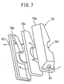
- the air cleaner 78 includes an air filter 78c in a case constituted of a right case 78a and a left case 78b.
- an inlet port 81 for taking in the air is provided, and in a principal surface of the left case 78b, an outlet port 82 is provided.
- the suction pipe 80 is connected to the outlet port 82.
- the air cleaner 78 is attached to the vehicle body in a state where the inlet port 81 is directed downward and diagonally right from the vehicle body.
- a notch part 78d is provided, and in this notch part 78d, the blower motor 74 of the blower main body 75 is housed.
- the pressure in the suction pipe 80 becomes a negative pressure and the air is sucked in from the inlet port 81 of the air cleaner 78.
- This air is filtered through the air filter 78c in the air cleaner 78 and, thereafter, is sucked into the suction pipe 80 from the outlet port 82. Subsequently, the air is supplied to a fan duct 76 through the blower motor 74.
- blower module 70 When an unillustrated ignition switch is turned on, the blower module 70 is driven, and suction and pressure feed of the air are started.
- the air is introduced, as the scavenging gas, into the fuel cell box 44 through a scavenging gas supply path 87 from an upstream by-pass valve 84 of the fan duct 76.
- a downstream by-pass valve 86 is opened, the air is supplied to the fuel cell stack 42 through a reactive gas supply path 88 (also see FIG. 9) and through a coolant gas supply path 90.
- a stack temperature Tbat of the fuel cell stack 42 is constantly measured by an unillustrated temperature sensor.
- the stack temperature Tbat is compared with a predetermined reference temperature Tref.
- the downstream by-pass valve 86 is controlled in the following manner. Specifically, if Tbat ⁇ Tref, the air supplied from the fan duct 76 is supplied to neither the reactive gas supply path 88 nor the coolant gas supply path 90, and if Tbat ⁇ Tref, the supply of the air to the reactive gas supply path 88 is stopped and only the supply thereof to the coolant gas supply path 90 is continued.
- a scavenging gas outlet path 92 for discharging the scavenging gas and a hydrogen outlet path 94 for discharging purged fuel gas (hydrogen gas) are further connected.
- Other ends of the respective paths are connected to a silencer 96 which also functions as a dilution box for hydrogen.
- the scavenging gas and the purged hydrogen gas are mixed by the silencer 96 and discharged to the air.
- the fuel cylinder 14 and the fuel cell box 44 are connected to each other by a fuel gas supply path 98, and through this fuel gas supply path 98, the fuel gas is supplied to the fuel cell stack 42 in the fuel cell box 44 from the fuel cylinder 14. Voltages of respective cells included in the fuel cell stack 42 are constantly monitored, and if even one of the voltages falls below a reference voltage, hydrogen purging for securing predetermined power generation efficiency or more is performed.
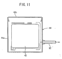
- FIGS. 10 and 11 are cross-sectional views of the fuel cell box 44 along the line X-X and the line XI-XI, respectively.
- the approximately cuboid fuel cell stack 42 is supported in such a manner that a space for scavenging is secured between six faces thereof and box cases 44a and 44b.
- the air introduced as the scavenging gas into the fuel cell box 44 from the scavenging gas supply path 87 is discharged from the scavenging gas outlet path 92 after scavenging the gas staying in the space between the box cases 44a and 44b and the fuel cell stack 42.
- FIG. 13 is a perspective view schematically showing a configuration of a gas diffusion mechanism 100 which includes the valve assembly 50 forming the fuel cylinder 14, and the upper frames 22L and 22R in the vehicle body frame 12.
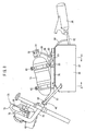
- FIG. 12 is a schematic plan view for explaining the gas diffusion mechanism 100.
- the gas diffusion mechanism 100 includes the pressure control valve 58, a diffusion guide 102 and the upper frame 22R included in the vehicle body frame 12.
- the pressure control valve 58 as the gas discharger which is attached to the valve assembly 50 of the fuel cylinder 14, includes the gas discharge port 59, and this gas discharge port 59 is disposed so as to face the diffusion guide 102 provided in the upper frame 22R.
- the diffusion guide 102 has a bowl shape, and a surface facing the gas discharge port 59 is formed to be a concave part 104. In four spots of this concave part 104, openings 106 are provided. The openings 106 are opened along a direction in parallel with the upper frame 22R and along a direction orthogonal thereto.
- a diameter L2 of the diffusion guide 102 is larger than that of the gas discharge port 59.
- a size of the diffusion guide 102 is set to such a size that the high-pressure fuel gas discharged from the cone-shaped gas discharge port 59 is diffused after always hitting against the diffusion guide 102.
- a width L1 of an attachment surface for the diffusion guide 102 in the upper frame 22R is larger than the maximum diameter L2 of the diffusion guide 102.
- the diffusion guide 102 is screwed on a boss provided in the upper frame 22R through the bowl-shaped bottom thereof, for example.
- the diffusion guide 102 may have a configuration in which the diffusion guide 102 is fixed to two bosses by use of two screws and thus the rotation thereof is prevented.
- the following configuration can be also adopted. Specifically, a screw-like protrusion having an irregular shape, such as a screw having a square head, is provided in the upper frame 22R, and this screw-like protrusion is pressed into a concave part which is provided in the bottom of the diffusion guide 102 and has a shape corresponding to the screw having the irregular shape.
- the diffusion guide 102 is fixed through one-touch operation.
- the pressure control valve 58 is a pressure control valve for limiting the maximum pressure of the fuel cylinder 14.
- a pressure control valve 58 for example, a spring tension and the internal fuel gas pressure is oppositely applied to the valve body, and the pressure control valve 58 has a function of opening the valve body and discharging the part of the fuel gas equivalent to an excess pressure through the gas discharge port 50 as indicated by the arrow 110 when the internal fuel gas pressure exceeds the spring tension.
- the high-pressure fuel gas discharged in the direction of the arrow 110 from the gas discharge port 59 has its pressure weakened when hitting against the concave part 104 of the diffusion guide 102. Moreover, the fuel gas has its pressure further weakened when being radially diffused as indicated by the arrow 111 along the concave part 104. Thereafter, the fuel gas is discharged to the air. A part of the gas passing through the diffusion guide 102 via the openings 106 hits against an approximately plate-like wall surface of the upper frame 22R and is further attenuated and rectified. Accordingly, the gas is diffused as indicated by the arrow 112 along the wall surface and is radially discharged to the air. As described above, the high-pressure fuel gas which has hit against the upper frame 22R and the diffusion guide 102 has its force attenuated and is diffused quickly and efficiently in respective directions.
- the fuel cell motorcycle 10 is covered with a vehicle body cover 126 including a front cowl 120, a center cowl 122 and left and right side cowls 124L and 124R.
- a vehicle body cover 126 including a front cowl 120, a center cowl 122 and left and right side cowls 124L and 124R.
- the width L1 of the upper frame 22R is set to such a width that the high-pressure fuel gas discharged from the gas discharge port 59 is diffused after always hitting against the upper frame 22R.
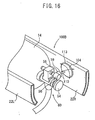
- a gas diffusion mechanism 100B has a configuration in which a diffusion guide 113 having no openings 106 and using its entire surface as a concave part is disposed so as to face the gas discharge port 59, the fuel gas discharged from the gas discharge port 59 hits against the diffusion guide 113 and is diffused in all directions. Thus, a certain diffusion effect can be obtained.
- the most efficient diffusion is possible by use of the gas diffusion mechanism 100 in the example shown in FIG. 13, in which the diffusion guide 102 having the openings 106 is provided in the vehicle body frame (the upper frame 22R).
- the efficient diffusion is possible in the order: the gas diffusion mechanism 100B in the example shown in FIG. 16, in which the diffusion guide 113 having no openings is provided in the vehicle body frame (the upper frame 22R); and the gas diffusion mechanism 100A in the example shown in FIG. 15, in which the discharged gas is diffused only by the vehicle body frame (the upper frame 22R).
- Which one of the gas diffusion mechanisms 100, 100A and 100B to be used can be determined by taking into consideration the discharge pressure from the gas discharge port 59, the shape of the upper frame 22R and the like.
- the present invention is not limited to the embodiment described above. It is needless to say that, based on the description of the present specification, various configurations can be adopted. For example, the present invention is similarly applicable to a three-wheeled fuel cell vehicle and a four-wheeled fuel cell vehicle besides the fuel cell motorcycle 10.
Landscapes
- Engineering & Computer Science (AREA)
- Life Sciences & Earth Sciences (AREA)
- Sustainable Development (AREA)
- Sustainable Energy (AREA)
- Chemical & Material Sciences (AREA)
- Transportation (AREA)
- Mechanical Engineering (AREA)
- Combustion & Propulsion (AREA)
- Power Engineering (AREA)
- Chemical Kinetics & Catalysis (AREA)
- Electrochemistry (AREA)
- General Chemical & Material Sciences (AREA)
- Fuel Cell (AREA)
- Filling Or Discharging Of Gas Storage Vessels (AREA)
- Automatic Cycles, And Cycles In General (AREA)
- Arrangement Or Mounting Of Propulsion Units For Vehicles (AREA)
Abstract
Description
Japanese Patent Laid-Open No. 2001-130468 (Fig. 1)
- 12
- vehicle body frame
- 14
- fuel cylinder
- 22L, 22R
- upper frame
- 50
- valve assembly
- 58
- pressure control valve
- 59
- gas discharge port
- 100, 100A, 100B
- gas diffusion mechanism
- 102, 113
- diffusion guide
- 104
- concave part
- 106
- opening
Claims (5)
- A fuel cell vehicle, which includes a fuel cylinder (14) and a fuel cell stack (42), and runs by electric power obtained by supplying reactive gas and fuel gas from the fuel cylinder (14) to the fuel cell stack (42), comprising:wherein the gas discharge port (59) is disposed so as to face the vehicle body frame (12).a vehicle body frame (12) which surrounds and supports the fuel cylinder (14), when planarly viewed; anda gas discharger which is provided in the fuel cylinder (14), has a gas discharge port (59) and discharges the fuel gas in the fuel cylinder (14) to the air through the gas discharge port (59),
- The fuel cell vehicle according to claim 1, further comprising:a diffusion guide (102, 113), in the vehicle body frame (12) disposed so as to face the gas discharge port (59), for diffusing the fuel gas discharged from the gas discharge port (59) into a plurality of directions.
- The fuel cell vehicle according to claim 1 or 2, wherein
a concave part (104) is formed on a surface facing the gas discharge port (59) in the diffusion guide (102, 113), and a plurality of openings through which a part of the fuel gas passes are provided in the concave part (104). - The fuel cell vehicle according to any one of claims 1 to 3, further comprising:wherein an opening for discharging the fuel gas diffused by the vehicle body frame (12) or the diffusion guide (102, 113) to the air outside of the vehicle body cover (126) is provided near any of the vehicle body frame (12), against which the fuel gas hits, and the diffusion guide (102, 113) in the vehicle body cover (126).a vehicle body cover (126) which covers the vehicle body frame (12) surrounding and supporting the fuel cylinder (14),
- The fuel cell vehicle according to any one of claims 1 to 4, wherein
the gas discharger is a pressure control valve (58) which discharges the fuel gas by automatically opening the gas discharge port (59) when a fuel gas pressure in the fuel cylinder (14) exceeds a predetermined value.
Applications Claiming Priority (2)
| Application Number | Priority Date | Filing Date | Title |
|---|---|---|---|
| JP2003388734 | 2003-11-19 | ||
| JP2003388734A JP4081430B2 (en) | 2003-11-19 | 2003-11-19 | Fuel cell vehicle |
Publications (3)
| Publication Number | Publication Date |
|---|---|
| EP1533173A2 true EP1533173A2 (en) | 2005-05-25 |
| EP1533173A3 EP1533173A3 (en) | 2006-09-27 |
| EP1533173B1 EP1533173B1 (en) | 2007-07-04 |
Family
ID=34431563
Family Applications (1)
| Application Number | Title | Priority Date | Filing Date |
|---|---|---|---|
| EP04026582A Expired - Lifetime EP1533173B1 (en) | 2003-11-19 | 2004-11-09 | Fuel cell vehicle |
Country Status (6)
| Country | Link |
|---|---|
| US (1) | US7108027B2 (en) |
| EP (1) | EP1533173B1 (en) |
| JP (1) | JP4081430B2 (en) |
| CN (1) | CN100404305C (en) |
| DE (1) | DE602004007343T2 (en) |
| TW (1) | TWI243128B (en) |
Cited By (4)
| Publication number | Priority date | Publication date | Assignee | Title |
|---|---|---|---|---|
| EP1767448A1 (en) * | 2005-09-26 | 2007-03-28 | Yamaha Hatsudoki Kabushiki Kaisha | Electric vehicle |
| US7550942B2 (en) | 2005-12-21 | 2009-06-23 | Yamaha Hatsudoki Kabushiki Kaisha | Hybrid power supply system and controller for warm-up mode |
| EP2236403A3 (en) * | 2009-04-03 | 2012-04-18 | Suzuki Motor Corporation | Gaseous fuel filling port arrangement structure for a motorcycle |
| DE102006053961B4 (en) * | 2005-11-30 | 2020-10-22 | Honda Motor Co., Ltd. | Fuel cell powered motorcycle |
Families Citing this family (34)
| Publication number | Priority date | Publication date | Assignee | Title |
|---|---|---|---|---|
| JP4079430B2 (en) * | 2003-07-11 | 2008-04-23 | 本田技研工業株式会社 | Fuel cell vehicle |
| JP4526800B2 (en) * | 2003-11-12 | 2010-08-18 | 本田技研工業株式会社 | Fuel cell discharge device |
| JP4081430B2 (en) * | 2003-11-19 | 2008-04-23 | 本田技研工業株式会社 | Fuel cell vehicle |
| GB2418539A (en) * | 2004-09-23 | 2006-03-29 | Vetco Gray Controls Ltd | Electrical circuit package |
| JP4383327B2 (en) * | 2004-11-30 | 2009-12-16 | 本田技研工業株式会社 | Release tube mounting structure for fuel cell vehicle and gas fuel vehicle |
| JP2006168548A (en) * | 2004-12-16 | 2006-06-29 | Yamaha Motor Co Ltd | vehicle |
| GB2422717B (en) * | 2005-02-01 | 2007-11-14 | Intelligent Energy Ltd | Detachable fuel cell power unit for vehicle applications |
| JP4648149B2 (en) * | 2005-09-30 | 2011-03-09 | 本田技研工業株式会社 | Fuel cell motorcycle |
| JP4771410B2 (en) * | 2005-10-25 | 2011-09-14 | 本田技研工業株式会社 | Fuel cell motorcycle |
| EP1963547B1 (en) * | 2005-12-23 | 2019-07-03 | Quantum Fuel Systems LLC | Safety warning and shutdown device and method for hydrogen storage containers |
| JP2007188712A (en) * | 2006-01-12 | 2007-07-26 | Yamaha Motor Co Ltd | Fuel cell system and electric vehicle equipped with the same |
| JP4804969B2 (en) * | 2006-03-16 | 2011-11-02 | 本田技研工業株式会社 | Front structure of a fuel cell vehicle |
| JP2007294116A (en) * | 2006-04-21 | 2007-11-08 | Yamaha Motor Co Ltd | Fuel cell system |
| US7913784B2 (en) * | 2007-03-30 | 2011-03-29 | Honda Motor Co., Ltd. | Saddle ride, fuel cell powered vehicle |
| JP2009013801A (en) * | 2007-07-02 | 2009-01-22 | Kawasaki Heavy Ind Ltd | Motorcycle with valve mechanism |
| JP5061816B2 (en) * | 2007-09-25 | 2012-10-31 | スズキ株式会社 | Fuel leak detection structure for fuel cell motorcycles |
| JP5055080B2 (en) * | 2007-10-03 | 2012-10-24 | ヤマハ発動機株式会社 | vehicle |
| JP5086831B2 (en) * | 2008-02-19 | 2012-11-28 | 本田技研工業株式会社 | Motorcycle |
| US20110247726A1 (en) * | 2008-12-11 | 2011-10-13 | Toyota Jidosha Kabushiki Kaisha | Gas filling system, gas fuel vehicle and gas station |
| JP5210939B2 (en) * | 2009-03-30 | 2013-06-12 | 本田技研工業株式会社 | Saddle riding |
| JP5305156B2 (en) * | 2009-03-30 | 2013-10-02 | スズキ株式会社 | Arrangement structure of motorcycle gas fuel tank |
| JP5387132B2 (en) | 2009-05-20 | 2014-01-15 | スズキ株式会社 | Fuel tank support structure for scooter type fuel cell motorcycle |
| JP5417992B2 (en) * | 2009-05-27 | 2014-02-19 | スズキ株式会社 | Fuel cell vehicle |
| DE102009030358C5 (en) * | 2009-06-18 | 2016-09-15 | Deutsches Zentrum für Luft- und Raumfahrt e.V. | Fuel cell system and method for its operation and its use |
| EP2457762B1 (en) * | 2009-07-21 | 2014-12-10 | Toyota Jidosha Kabushiki Kaisha | Fuel system and vehicle |
| JP5694788B2 (en) * | 2011-01-17 | 2015-04-01 | 本田技研工業株式会社 | Saddle riding vehicle |
| JP5879878B2 (en) * | 2011-09-28 | 2016-03-08 | スズキ株式会社 | Motorcycle |
| JP6413873B2 (en) * | 2015-03-24 | 2018-10-31 | スズキ株式会社 | Saddle type fuel cell vehicle |
| US11253501B2 (en) | 2015-06-01 | 2022-02-22 | Lupin Inc. | Secnidazole formulations and use in treating bacterial vaginosis |
| US9975415B2 (en) * | 2016-02-16 | 2018-05-22 | General Electric Company | Cooling arrangement for a motor of a vehicle |
| DE102016212153A1 (en) * | 2016-07-04 | 2018-01-04 | Bayerische Motoren Werke Aktiengesellschaft | Anode subsystem with a mechanical anode flush valve and method for flushing an anode subsystem |
| DE102018209047A1 (en) * | 2018-06-07 | 2019-12-12 | Robert Bosch Gmbh | Device for temperature pressure relief of a fuel tank |
| JP2025030886A (en) * | 2023-08-24 | 2025-03-07 | スズキ株式会社 | Saddle-type vehicle |
| JP2025068957A (en) * | 2023-10-17 | 2025-04-30 | カワサキモータース株式会社 | Vehicle and tank cover |
Citations (1)
| Publication number | Priority date | Publication date | Assignee | Title |
|---|---|---|---|---|
| JP2001130468A (en) | 1999-11-04 | 2001-05-15 | Yamaha Motor Co Ltd | Motorcycles and tricycles with fuel cells |
Family Cites Families (14)
| Publication number | Priority date | Publication date | Assignee | Title |
|---|---|---|---|---|
| JP3391423B2 (en) * | 1994-09-30 | 2003-03-31 | 本田技研工業株式会社 | Attachment structure of the tip of the pipe for leaking compressed fuel gas from automobiles |
| JP4382250B2 (en) * | 2000-04-28 | 2009-12-09 | ヤマハ発動機株式会社 | Drainage device for fuel cell vehicle |
| JP2001351653A (en) * | 2000-06-02 | 2001-12-21 | Yamaha Motor Co Ltd | Fuel cell system |
| JP2001354179A (en) * | 2000-06-14 | 2001-12-25 | Honda Motor Co Ltd | Motorcycle with fuel cell |
| CN2433115Y (en) * | 2000-07-19 | 2001-06-06 | 黄勇和 | Configuration structure of electric motorcycle with fuel cell as energy system |
| CN2440694Y (en) * | 2000-07-19 | 2001-08-01 | 黄勇和 | Fuel cell hydrogen storage device for electric motorcycle |
| JP3813427B2 (en) * | 2000-09-22 | 2006-08-23 | 本田技研工業株式会社 | Gas discharge structure of gaseous fuel |
| JP4027044B2 (en) * | 2001-01-16 | 2007-12-26 | 本田技研工業株式会社 | Gaseous fuel gas discharge structure for vehicles |
| JP3970531B2 (en) * | 2001-02-19 | 2007-09-05 | 本田技研工業株式会社 | Gaseous fuel gas discharge structure |
| CA2384915C (en) * | 2001-05-04 | 2007-02-06 | Dynetek Industries Ltd. | Pressure vessel mounting system |
| US6568496B1 (en) * | 2001-11-20 | 2003-05-27 | Yung Ho Huang | Electromotive motorcycle arranged with power system using fuel cell |
| JP4093929B2 (en) * | 2003-07-11 | 2008-06-04 | 本田技研工業株式会社 | Fuel cell vehicle |
| JP4082597B2 (en) * | 2003-07-11 | 2008-04-30 | 本田技研工業株式会社 | Fuel cell vehicle |
| JP4081430B2 (en) * | 2003-11-19 | 2008-04-23 | 本田技研工業株式会社 | Fuel cell vehicle |
-
2003
- 2003-11-19 JP JP2003388734A patent/JP4081430B2/en not_active Expired - Fee Related
-
2004
- 2004-11-01 TW TW093133257A patent/TWI243128B/en not_active IP Right Cessation
- 2004-11-05 US US10/998,231 patent/US7108027B2/en not_active Expired - Fee Related
- 2004-11-09 EP EP04026582A patent/EP1533173B1/en not_active Expired - Lifetime
- 2004-11-09 DE DE602004007343T patent/DE602004007343T2/en not_active Expired - Lifetime
- 2004-11-16 CN CNB2004100946039A patent/CN100404305C/en not_active Expired - Fee Related
Patent Citations (1)
| Publication number | Priority date | Publication date | Assignee | Title |
|---|---|---|---|---|
| JP2001130468A (en) | 1999-11-04 | 2001-05-15 | Yamaha Motor Co Ltd | Motorcycles and tricycles with fuel cells |
Cited By (4)
| Publication number | Priority date | Publication date | Assignee | Title |
|---|---|---|---|---|
| EP1767448A1 (en) * | 2005-09-26 | 2007-03-28 | Yamaha Hatsudoki Kabushiki Kaisha | Electric vehicle |
| DE102006053961B4 (en) * | 2005-11-30 | 2020-10-22 | Honda Motor Co., Ltd. | Fuel cell powered motorcycle |
| US7550942B2 (en) | 2005-12-21 | 2009-06-23 | Yamaha Hatsudoki Kabushiki Kaisha | Hybrid power supply system and controller for warm-up mode |
| EP2236403A3 (en) * | 2009-04-03 | 2012-04-18 | Suzuki Motor Corporation | Gaseous fuel filling port arrangement structure for a motorcycle |
Also Published As
| Publication number | Publication date |
|---|---|
| CN1618650A (en) | 2005-05-25 |
| TWI243128B (en) | 2005-11-11 |
| EP1533173A3 (en) | 2006-09-27 |
| CN100404305C (en) | 2008-07-23 |
| DE602004007343T2 (en) | 2008-03-06 |
| US20050133283A1 (en) | 2005-06-23 |
| DE602004007343D1 (en) | 2007-08-16 |
| JP4081430B2 (en) | 2008-04-23 |
| JP2005145359A (en) | 2005-06-09 |
| EP1533173B1 (en) | 2007-07-04 |
| US7108027B2 (en) | 2006-09-19 |
| TW200524773A (en) | 2005-08-01 |
Similar Documents
| Publication | Publication Date | Title |
|---|---|---|
| EP1533173B1 (en) | Fuel cell vehicle | |
| US9543598B2 (en) | Fuel cell-powered motorcycle | |
| EP1495955B1 (en) | Fuel cell vehicle | |
| US6648085B2 (en) | Fuel-cell-powered four-wheel automobile | |
| US7234551B2 (en) | Fuel cell vehicle | |
| JP5035886B2 (en) | Saddle type fuel cell vehicle | |
| EP2255985B1 (en) | Fuel cell powered vehicle | |
| JP2008247325A (en) | Saddle type fuel cell vehicle | |
| JP2009006971A (en) | Saddle type fuel cell vehicle | |
| US7368197B2 (en) | Fuel cell vehicle | |
| JP6331838B2 (en) | Fuel cell motorcycle | |
| JP4455222B2 (en) | Intake / exhaust system member arrangement structure in fuel cell vehicle | |
| JP4079433B2 (en) | Fuel cell vehicle | |
| JP2009154761A (en) | Motorcycle | |
| JP4422579B2 (en) | Fuel cell vehicle | |
| JP4497276B2 (en) | Vehicle fuel cell system | |
| JP4681264B2 (en) | Motorcycle tail lamp structure | |
| JP2006339096A (en) | Arrangement structure of intake system members in fuel cell vehicle |
Legal Events
| Date | Code | Title | Description |
|---|---|---|---|
| PUAI | Public reference made under article 153(3) epc to a published international application that has entered the european phase |
Free format text: ORIGINAL CODE: 0009012 |
|
| AK | Designated contracting states |
Kind code of ref document: A2 Designated state(s): AT BE BG CH CY CZ DE DK EE ES FI FR GB GR HU IE IS IT LI LU MC NL PL PT RO SE SI SK TR |
|
| AX | Request for extension of the european patent |
Extension state: AL HR LT LV MK YU |
|
| PUAL | Search report despatched |
Free format text: ORIGINAL CODE: 0009013 |
|
| AK | Designated contracting states |
Kind code of ref document: A3 Designated state(s): AT BE BG CH CY CZ DE DK EE ES FI FR GB GR HU IE IS IT LI LU MC NL PL PT RO SE SI SK TR |
|
| AX | Request for extension of the european patent |
Extension state: AL HR LT LV MK YU |
|
| RIC1 | Information provided on ipc code assigned before grant |
Ipc: B60L 11/18 20060101AFI20050301BHEP Ipc: B60K 15/073 20060101ALI20060821BHEP Ipc: B60K 15/03 20060101ALI20060821BHEP |
|
| 17P | Request for examination filed |
Effective date: 20061128 |
|
| GRAP | Despatch of communication of intention to grant a patent |
Free format text: ORIGINAL CODE: EPIDOSNIGR1 |
|
| AKX | Designation fees paid |
Designated state(s): DE FR IT |
|
| GRAS | Grant fee paid |
Free format text: ORIGINAL CODE: EPIDOSNIGR3 |
|
| GRAA | (expected) grant |
Free format text: ORIGINAL CODE: 0009210 |
|
| AK | Designated contracting states |
Kind code of ref document: B1 Designated state(s): DE FR IT |
|
| REF | Corresponds to: |
Ref document number: 602004007343 Country of ref document: DE Date of ref document: 20070816 Kind code of ref document: P |
|
| ET | Fr: translation filed | ||
| PLBE | No opposition filed within time limit |
Free format text: ORIGINAL CODE: 0009261 |
|
| STAA | Information on the status of an ep patent application or granted ep patent |
Free format text: STATUS: NO OPPOSITION FILED WITHIN TIME LIMIT |
|
| 26N | No opposition filed |
Effective date: 20080407 |
|
| PGFP | Annual fee paid to national office [announced via postgrant information from national office to epo] |
Ref country code: DE Payment date: 20121107 Year of fee payment: 9 Ref country code: FR Payment date: 20121130 Year of fee payment: 9 |
|
| PGFP | Annual fee paid to national office [announced via postgrant information from national office to epo] |
Ref country code: IT Payment date: 20121113 Year of fee payment: 9 |
|
| REG | Reference to a national code |
Ref country code: FR Ref legal event code: ST Effective date: 20140731 |
|
| REG | Reference to a national code |
Ref country code: DE Ref legal event code: R119 Ref document number: 602004007343 Country of ref document: DE Effective date: 20140603 |
|
| PG25 | Lapsed in a contracting state [announced via postgrant information from national office to epo] |
Ref country code: DE Free format text: LAPSE BECAUSE OF NON-PAYMENT OF DUE FEES Effective date: 20140603 Ref country code: IT Free format text: LAPSE BECAUSE OF NON-PAYMENT OF DUE FEES Effective date: 20131109 |
|
| PG25 | Lapsed in a contracting state [announced via postgrant information from national office to epo] |
Ref country code: FR Free format text: LAPSE BECAUSE OF NON-PAYMENT OF DUE FEES Effective date: 20131202 |