EP1533148A1 - System und Verfahren zur Bestimmung wenigstens eines Parameters wenigstens eines drehenden Organs mittels Referenz- und Geschwindigkeitsignalen - Google Patents
System und Verfahren zur Bestimmung wenigstens eines Parameters wenigstens eines drehenden Organs mittels Referenz- und Geschwindigkeitsignalen Download PDFInfo
- Publication number
- EP1533148A1 EP1533148A1 EP04292640A EP04292640A EP1533148A1 EP 1533148 A1 EP1533148 A1 EP 1533148A1 EP 04292640 A EP04292640 A EP 04292640A EP 04292640 A EP04292640 A EP 04292640A EP 1533148 A1 EP1533148 A1 EP 1533148A1
- Authority
- EP
- European Patent Office
- Prior art keywords
- transponder
- activation
- encoder
- detection device
- parameter
- Prior art date
- Legal status (The legal status is an assumption and is not a legal conclusion. Google has not performed a legal analysis and makes no representation as to the accuracy of the status listed.)
- Withdrawn
Links
- 238000000034 method Methods 0.000 title claims abstract description 36
- 230000004913 activation Effects 0.000 claims abstract description 49
- 238000001514 detection method Methods 0.000 claims abstract description 42
- 238000004891 communication Methods 0.000 claims abstract description 22
- 230000005540 biological transmission Effects 0.000 claims abstract description 8
- 230000005284 excitation Effects 0.000 claims description 9
- 230000003213 activating effect Effects 0.000 claims description 7
- 238000005259 measurement Methods 0.000 claims description 7
- 238000005457 optimization Methods 0.000 claims description 6
- 230000005405 multipole Effects 0.000 claims description 2
- 230000007704 transition Effects 0.000 claims description 2
- 230000001419 dependent effect Effects 0.000 claims 2
- 210000000056 organ Anatomy 0.000 claims 1
- 230000003287 optical effect Effects 0.000 description 3
- 230000001960 triggered effect Effects 0.000 description 2
- JBRZTFJDHDCESZ-UHFFFAOYSA-N AsGa Chemical compound [As]#[Ga] JBRZTFJDHDCESZ-UHFFFAOYSA-N 0.000 description 1
- 229910017214 AsGa Inorganic materials 0.000 description 1
- 230000005355 Hall effect Effects 0.000 description 1
- XUIMIQQOPSSXEZ-UHFFFAOYSA-N Silicon Chemical compound [Si] XUIMIQQOPSSXEZ-UHFFFAOYSA-N 0.000 description 1
- 230000001133 acceleration Effects 0.000 description 1
- 230000009471 action Effects 0.000 description 1
- 230000000712 assembly Effects 0.000 description 1
- 238000000429 assembly Methods 0.000 description 1
- 230000008859 change Effects 0.000 description 1
- 230000005611 electricity Effects 0.000 description 1
- 238000005516 engineering process Methods 0.000 description 1
- 239000011521 glass Substances 0.000 description 1
- 230000010354 integration Effects 0.000 description 1
- 239000002184 metal Substances 0.000 description 1
- 230000000737 periodic effect Effects 0.000 description 1
- 239000000523 sample Substances 0.000 description 1
- 229910052710 silicon Inorganic materials 0.000 description 1
- 239000010703 silicon Substances 0.000 description 1
- 239000000758 substrate Substances 0.000 description 1
Images
Classifications
-
- B—PERFORMING OPERATIONS; TRANSPORTING
- B60—VEHICLES IN GENERAL
- B60C—VEHICLE TYRES; TYRE INFLATION; TYRE CHANGING; CONNECTING VALVES TO INFLATABLE ELASTIC BODIES IN GENERAL; DEVICES OR ARRANGEMENTS RELATED TO TYRES
- B60C23/00—Devices for measuring, signalling, controlling, or distributing tyre pressure or temperature, specially adapted for mounting on vehicles; Arrangement of tyre inflating devices on vehicles, e.g. of pumps or of tanks; Tyre cooling arrangements
- B60C23/02—Signalling devices actuated by tyre pressure
- B60C23/04—Signalling devices actuated by tyre pressure mounted on the wheel or tyre
- B60C23/0408—Signalling devices actuated by tyre pressure mounted on the wheel or tyre transmitting the signals by non-mechanical means from the wheel or tyre to a vehicle body mounted receiver
- B60C23/0422—Signalling devices actuated by tyre pressure mounted on the wheel or tyre transmitting the signals by non-mechanical means from the wheel or tyre to a vehicle body mounted receiver characterised by the type of signal transmission means
- B60C23/0433—Radio signals
Definitions
- the invention relates to a system for determining at least one parameter of at least one rotating member with respect to a fixed structure, a method of determination of at least one such parameter as well as a motor vehicle including such a system.
- the invention typically applies to the determination of at least one parameter, such as the pressure, temperature, deformation and wear of a tire of motor vehicle.
- the antenna of the latter is positioned near the area of moving the transponder, typically in the wheel well.
- the detection device by activating the detection device, it is possible to obtain periodically the value of the parameter (s) measured by the transponder and make this value available to a system, for example security of the vehicle, who controls it and / or uses it.
- a problem that arises is the establishment of an activation procedure of the detection device which makes it possible to obtain a communication satisfactory between said device and the transponder. Indeed, the antenna with a given transmit / receive cone, activation must be performed when the transponder is in this cone.
- the invention proposes in particular a system of determination which makes it possible to synchronize the communication between the antenna and the transponder when it is in the cone transmission / reception, so as to secure communication by optimizing electricity consumption, while being able to adapt the frequency of communication to the operating conditions of the vehicle.
- the invention proposes a determination method of at least one parameter of at least one rotating member with respect to a fixed structure by means of such a system, in which, when recording of a reference pulse, the activation device determines a delay activation according to the measured speed and the indexed position of the transponder, said device activating the detection device after the flow this period.
- the invention proposes a motor vehicle comprising such a system, each set being arranged so as to determine at least one parameter of a tire of said vehicle.
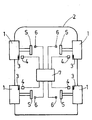
- the invention relates to a system for determining at least one parameter at least one rotating member 1 rotating relative to a fixed structure 2.
- this system is for determining at least one parameter of at least one tire 1 of a motor vehicle.
- the system allows the determination of the pressure, temperature, deformation and / or wear of all tires 1 of the vehicle.
- the system comprises, for each tire 1, a set comprising a transponder 3 able to measure the parameter (s) to determine, and a detection device 4 of the parameter (s) issued from the transponder 3.
- the transponder 3 is integral in rotation with the tire 1 and the detection device 4 is integral, in the vicinity of the transponder 3, the chassis 2 of the vehicle.
- the transponder 3 can be integral with the wheel or bearing on which the wheel is mounted.
- the determination system allows, by activating the detection device 4, periodically obtain the value of the parameter (s) measured by the transponder 3 and make this value available to a fixed system by relative to the chassis 2, for example vehicle safety, who controls it and / or used.
- the automatic determination of the parameter (s) may be used to warn the driver in the event of a fault.
- the Parameter (s) can be used in such driver assistance systems anti-lock wheels (ABS), trajectory control (ESP) or management assistance (DAE), so as to adapt the action of these systems according to the value of the determined parameters.
- the antenna is housed in the passage of the wheel on which is mounted the tire 1 and the transponder 3 is housed in the valve of the tire 1.
- the distance antenna - transponder 3 is reduced, which allows to optimize the electric power necessary for the communication of measurements between the tire 1 and the chassis 2.
- the transponder 3 is disposed in the tread of the tire 1, in particular to measure the deformation and wear of it.
- the assembly further comprises an encoder 5 integral in rotation with the tire 1 and a sensor 6 secured to the frame 2 of the vehicle.
- the encoder 5 and / or the sensor 6 can be arranged at the wheel bearing such that is for example described in document FR-2 700 588 issued by Applicant.
- the encoder 5 can in particular be secured in rotation to the rotating ring of the bearing and the sensor 6 can be associated with the fixed ring or dissociated from it, to be facing and reading distance from the encoder 5.
- the function of the encoder 5 is to deliver angular position information of reference.
- the encoder 5 comprises a reference singularity which, as will be seen in the remainder of the description, is indexed with respect to the angular position of the transponder 3 on the tire 1.
- the assembly also includes a device for measuring the speed of rotation of the tire 1.
- a device for measuring the speed of rotation of the tire 1 An embodiment is described below in which the The speed measuring device is integrated in the sensor 6. However, other embodiments comprising a separate speed measuring device are also possible.
- the encoder 5 is formed of a magnetic ring comprising on its surface a main track and a top-turn track which are concentric, said tracks comprising a succession of North poles and South, the reference singularity being achieved by a magnetic transition which is different from others.
- the senor 6 which comprises an electronic circuit which also forms a device for measuring the speed of rotation of the tire 1.
- the electronic circuit is suitable for to deliver a signal representative of the rotational speed of the encoder 5, and therefore that of the tire 1 since the encoder is integral in rotation with it, for compared to chassis 2 and a top-turn signal including a pulse of reference corresponding to the detection of the reference singularity.
- the senor 6 comprises at least three elements sensitive of which at least two are positioned opposite the main track and at least one is positioned next to the top-turn track.
- the sensitive elements are selected from the group including Hall effect probes, magnetoresistors, giant magnetoresistances.
- the sensor 6 used in this embodiment is capable of delivering two signals periodic electrical S1, S2 through quadrature elements sensed arranged opposite the main track and an electrical signal S3 by through the sensitive elements arranged next to the track top tower.
- sensors comprising two sensitive elements that are able to to deliver the signals S1 and S2 are also known.
- the electronic circuit is able to deliver digital signals A, B squares in quadrature and a top-turn signal C.
- the signals A, B being representative of the rotational speed of the encoder but also of its angular position as well as its direction of rotation.
- the electronic circuit further comprises a interpolator, for example of the type described in document FR-2 754 063 issued of the plaintiff, allowing to increase the resolution of the signals of exit.
- a interpolator for example of the type described in document FR-2 754 063 issued of the plaintiff, allowing to increase the resolution of the signals of exit.
- the sensor 6 can be integrated on a silicon substrate or equivalent by example AsGa, so as to form an integrated circuit and customized for a specific application, circuit sometimes referred to as ASIC to make reference to the integrated circuit designed partially or completely according to needs.
- the encoder 5 may be formed of a metal or glass target on which the tracks main and top tower have been engraved so as to form an optical pattern analogous to the multipole magnetic motif set out above, the elements Sensors are then formed of optical detectors.
- the system comprises an activation device 7, in the form of a computing unit, which is connected to each sensor 6, to each detection device 4 and to each device for measuring the speed, so as to be able to temporally synchronize the passage of the transponder 3 in the transmit / receive cone of the antenna of said detection device for collect the value of the parameter (s) detected.
- the activation device 7 is suitable, when recording a pulse of reference from the sensor 6 of a set, to activate the detection device 4 of the assembly at a given moment according to the indexed position of the transponder 3 and measured speed, so that the transponder 3 of the set is in the transmitting / receiving cone of the antenna of said detection device.
- the system according to the invention allows, thanks to the synchronization, to optimize the life of the battery supplying the activation device 7 and, if appropriate, the battery supplying the transponder 3 in the case where it is active.
- each coder 5 comprises coding means of the pulse which are different from one encoder to the other, the activation device 7 comprising means for identifying the coding so as to activate the detection device 4 of the entire encoder 5 from which the pulse.
- the activation device 7 can simplify the wiring between the assemblies and the activation device 7, since the recognition of the tire 1 concerned does not depends more on the physical addressing of the position signals to the device 7.
- the coding means comprise a number of additional singularities that are distributed over the encoder 5.
- the activation device 7 determines an activation delay depending on the speed measured and the indexed position of the transponder 3, the activation device 7 activating the detection device 4 after this period has elapsed.
- the method provides a procedure for recalculating the delay in function of speed variations occurring before activation.
- This procedure allows, in case of acceleration and / or deceleration of the vehicle between delay determination and activation, take into account the gear change to synchronize the passage of the transponder 3 in the cone transmission / reception.
- the activation device 7 is also powered with the relevant parameters and with the desired conditions so as to calculate the activation delay according to said operating conditions.
- the indexed position of the transponder 3 by reference to the reference singularity is previously stored in the activation device 7.
- this indexing is performed mechanically in the factory or in a workshop, on a bench capable of measuring the angular offset between the reference singularity and the transponder 3.
- the reference singularity is indexed relative to all the possible angular positions of the transponder 3 on the tire 1, these positions each corresponding to a mounting position possible of the wheel on the vehicle.
- the activation device 7 is able to activate the device 4 when each possible angular position of the transponder 3 is in the transmit / receive cone of the antenna. So for example for four possible positions, the detection device 4 will be activated four times, the communication being carried out satisfactorily only in one of the these positions.
- This embodiment allows, in case of assembly / disassembly of the wheel, not to have to re-index.
- the determination method comprises a prior procedure for indexing the position of the reference singularity by relative to the angular position of the transponder 3.
- This procedure can be performed by fixed frequency activation, for example every second, of the detection device 4 and, when the signal measured by the detection device 4 is satisfactory, determination and recording in the activation device 7 of the indexed position during the detection of the next reference pulse.
- this procedure can be triggered at each commissioning of the determination system, before the determination of the parameter (s) according to the invention.
- the optimization procedure may involve analyzing the quality of the signal from the detection device 4, for example its signal-to-noise ratio, the rate communication error, the power communicated. If this quality is less than a first threshold, incrementing and / or decrementing by a given step, for example, one degree, the indexed position. Iteratively, the procedure allows, by analyzing the quality of the corresponding signal, to increment or decrement the indexed position to obtain an optimized indexed position wherein the signal quality is maximum. This optimized position is later used as a new indexed position in the device activation 7.
- a second threshold of signal quality less than the first, is used in the activation device 7. if the signal quality is below the second threshold, indexing procedure instead of the optimization procedure.
- this realization allows, if the optimization procedure does not allow to converge to an optimized position, to start an indexing procedure in optimization course.
Landscapes
- Engineering & Computer Science (AREA)
- Mechanical Engineering (AREA)
- Arrangements For Transmission Of Measured Signals (AREA)
- Measurement Of Length, Angles, Or The Like Using Electric Or Magnetic Means (AREA)
- Selective Calling Equipment (AREA)
Applications Claiming Priority (2)
| Application Number | Priority Date | Filing Date | Title |
|---|---|---|---|
| FR0350879A FR2862751B1 (fr) | 2003-11-21 | 2003-11-21 | Systeme et procede de determination d'au moins un parametre d'au moins un organe tournant au moyen de signaux de reference et de vitesse |
| FR0350879 | 2003-11-21 |
Publications (1)
| Publication Number | Publication Date |
|---|---|
| EP1533148A1 true EP1533148A1 (de) | 2005-05-25 |
Family
ID=34430106
Family Applications (1)
| Application Number | Title | Priority Date | Filing Date |
|---|---|---|---|
| EP04292640A Withdrawn EP1533148A1 (de) | 2003-11-21 | 2004-11-08 | System und Verfahren zur Bestimmung wenigstens eines Parameters wenigstens eines drehenden Organs mittels Referenz- und Geschwindigkeitsignalen |
Country Status (4)
| Country | Link |
|---|---|
| US (1) | US7271733B2 (de) |
| EP (1) | EP1533148A1 (de) |
| JP (1) | JP2005158052A (de) |
| FR (1) | FR2862751B1 (de) |
Cited By (1)
| Publication number | Priority date | Publication date | Assignee | Title |
|---|---|---|---|---|
| CN111106448A (zh) * | 2019-11-22 | 2020-05-05 | Oppo广东移动通信有限公司 | 客户终端设备 |
Families Citing this family (5)
| Publication number | Priority date | Publication date | Assignee | Title |
|---|---|---|---|---|
| ATE508891T1 (de) * | 2006-09-19 | 2011-05-15 | Em Microelectronic Marin Sa | Verfahren zur prüfung der betriebsfähigkeit eines an einem kraftfahrzeugsrad eingebauten transponders |
| JP4511506B2 (ja) * | 2006-10-26 | 2010-07-28 | アルプス電気株式会社 | タイヤ状態監視装置 |
| CN103869094B (zh) * | 2012-12-14 | 2017-07-18 | 中国核动力研究设计院 | 一种主泵转速测量信号处理方法 |
| DE102014218370B4 (de) * | 2014-09-12 | 2018-10-25 | Saf-Holland Gmbh | System und Verfahren zum Erfassen und Auswerten einer Messgröße |
| DE102015220694A1 (de) * | 2015-10-22 | 2017-04-27 | Bayerische Motoren Werke Aktiengesellschaft | System und Verfahren zur Ermittlung des Reifendrucks eines Straßenfahrzeugs |
Citations (3)
| Publication number | Priority date | Publication date | Assignee | Title |
|---|---|---|---|---|
| FR2500926A1 (fr) * | 1981-03-02 | 1982-09-03 | Vdo Schindling | Dispositif pour transmettre une grandeur mesuree d'un objet mobile a un objet stationnaire par rapport a ce dernier |
| DE3818207A1 (de) * | 1988-05-28 | 1989-11-30 | Bosch Gmbh Robert | Reifendruck- und temperatursensor |
| FR2769088A1 (fr) * | 1997-09-26 | 1999-04-02 | Roulements Soc Nouvelle | Capteur digital de position relative |
Family Cites Families (5)
| Publication number | Priority date | Publication date | Assignee | Title |
|---|---|---|---|---|
| JPH0436613A (ja) * | 1990-06-01 | 1992-02-06 | Yamaha Corp | 磁気ロータリーエンコーダ |
| US6691567B2 (en) * | 2002-03-01 | 2004-02-17 | Lear Corporation | System and method for tire pressure monitoring including automatic tire location recognition |
| US6838985B2 (en) * | 2002-03-25 | 2005-01-04 | Lear Corporation | System and method for remote tire pressure monitoring with low frequency initiation |
| US6914523B2 (en) * | 2002-04-30 | 2005-07-05 | Trw Inc. | Method and apparatus for sensing tire pressure |
| JP3975973B2 (ja) * | 2003-06-05 | 2007-09-12 | トヨタ自動車株式会社 | 車輪−車体間通信システム |
-
2003
- 2003-11-21 FR FR0350879A patent/FR2862751B1/fr not_active Expired - Fee Related
-
2004
- 2004-10-29 JP JP2004316878A patent/JP2005158052A/ja not_active Ceased
- 2004-11-08 EP EP04292640A patent/EP1533148A1/de not_active Withdrawn
- 2004-11-16 US US10/988,570 patent/US7271733B2/en not_active Expired - Fee Related
Patent Citations (3)
| Publication number | Priority date | Publication date | Assignee | Title |
|---|---|---|---|---|
| FR2500926A1 (fr) * | 1981-03-02 | 1982-09-03 | Vdo Schindling | Dispositif pour transmettre une grandeur mesuree d'un objet mobile a un objet stationnaire par rapport a ce dernier |
| DE3818207A1 (de) * | 1988-05-28 | 1989-11-30 | Bosch Gmbh Robert | Reifendruck- und temperatursensor |
| FR2769088A1 (fr) * | 1997-09-26 | 1999-04-02 | Roulements Soc Nouvelle | Capteur digital de position relative |
Cited By (2)
| Publication number | Priority date | Publication date | Assignee | Title |
|---|---|---|---|---|
| CN111106448A (zh) * | 2019-11-22 | 2020-05-05 | Oppo广东移动通信有限公司 | 客户终端设备 |
| CN111106448B (zh) * | 2019-11-22 | 2021-10-19 | Oppo广东移动通信有限公司 | 客户终端设备 |
Also Published As
| Publication number | Publication date |
|---|---|
| JP2005158052A (ja) | 2005-06-16 |
| US20050110626A1 (en) | 2005-05-26 |
| US7271733B2 (en) | 2007-09-18 |
| FR2862751B1 (fr) | 2006-03-03 |
| FR2862751A1 (fr) | 2005-05-27 |
Similar Documents
| Publication | Publication Date | Title |
|---|---|---|
| EP1593532B1 (de) | System zur Steuerung des Reifenfülldrucks von Kraftfahrzeugrädern | |
| EP1403622B1 (de) | Absoluter Drehgeber | |
| EP3027496B1 (de) | Vorrichtung und verfahren zur regelung der hilfsleistung eines fahrrads mit elektrischem hilfsantrieb | |
| EP1167927A1 (de) | Vorrichtung zur erfassung eines absolutenwinkelpostition | |
| EP1743151B1 (de) | Deformationsmesslager mit vier belastungsmessgeräten | |
| FR2856142A1 (fr) | Determination de la position angulaire absolue d'un volant par mesure incrementale et mesure de la vitesse differentielle des roues | |
| FR2924518A1 (fr) | Dispositif de localisation de la position droite et gauche d'un ensemble pneumatique et roue d'un vehicule | |
| FR2847667A1 (fr) | Dispositif de detection de la position d'une roue de vehicule | |
| EP1882907B1 (de) | Verfahren zur Bestimmung zweier um 90 Grad phasenverschobener Signale | |
| FR2879330A1 (fr) | Procede et dispositif de determination de l'etat de deplacement d'un vehicule | |
| FR2862382A1 (fr) | Systeme capteur de couple absolu de torsion et module le comprenant | |
| EP1533147A2 (de) | System und Verfahren zur Feststellung von zumindest einem drehenden Teil durch Verwendung eines Ortungssignal | |
| FR2866269A1 (fr) | Dispositif et procede pour determiner la position laterale de roues | |
| EP1533148A1 (de) | System und Verfahren zur Bestimmung wenigstens eines Parameters wenigstens eines drehenden Organs mittels Referenz- und Geschwindigkeitsignalen | |
| EP1631793B1 (de) | Bestimmung der absoluten winkelposition eines lenkrads durch binärsequenz-diskrimination | |
| WO2017059938A1 (fr) | Unite electronique de roue et son procede de montage | |
| EP1403621B1 (de) | Absoluter Drehgeber | |
| EP1533620B1 (de) | Vorrichtung und Verfahren zur Bestimmung mindestens eines Parameters wenigstens eines drehenden Teiles mittels eines Absolutpositionssignals | |
| WO2019016455A1 (fr) | Procédé de localisation d'une position de chaque roue d'un véhicule automobile associée à un boîtier électronique | |
| FR2879750A1 (fr) | Procede de determination du sens de rotation d'une roue et dispositif mettant en oeuvre ce procede | |
| FR2919415A1 (fr) | Procede et dispositif de localisation des roues d'un vehicule. | |
| EP2523814B1 (de) | Verfahren zum austausch von signalen zwischen einem reifendrucksensor und einer zentralprozessoreinheit in einem motorfahrzeug | |
| WO2005121731A1 (fr) | Roulement capteur de deformations comprenant deux jauges de contraintes | |
| FR2932878A1 (fr) | Dispositif et procede de l'estimation de la pente du terrain pour le roulage d'un vehicule automobile. | |
| FR2949382A1 (fr) | Systeme de surveillance de pression de pneumatiques a calculateur embarque sur une roue de vehicule |
Legal Events
| Date | Code | Title | Description |
|---|---|---|---|
| PUAI | Public reference made under article 153(3) epc to a published international application that has entered the european phase |
Free format text: ORIGINAL CODE: 0009012 |
|
| AK | Designated contracting states |
Kind code of ref document: A1 Designated state(s): AT BE BG CH CY CZ DE DK EE ES FI FR GB GR HU IE IS IT LI LU MC NL PL PT RO SE SI SK TR |
|
| AX | Request for extension of the european patent |
Extension state: AL HR LT LV MK YU |
|
| 17P | Request for examination filed |
Effective date: 20051025 |
|
| AKX | Designation fees paid |
Designated state(s): AT BE BG CH CY CZ DE DK EE ES FI FR GB GR HU IE IS IT LI LU MC NL PL PT RO SE SI SK TR |
|
| GRAP | Despatch of communication of intention to grant a patent |
Free format text: ORIGINAL CODE: EPIDOSNIGR1 |
|
| STAA | Information on the status of an ep patent application or granted ep patent |
Free format text: STATUS: THE APPLICATION IS DEEMED TO BE WITHDRAWN |
|
| 18D | Application deemed to be withdrawn |
Effective date: 20100601 |