EP1533147A2 - System and process for the determination of the position of at least a rotating part by use of a position signal - Google Patents
System and process for the determination of the position of at least a rotating part by use of a position signal Download PDFInfo
- Publication number
- EP1533147A2 EP1533147A2 EP04292636A EP04292636A EP1533147A2 EP 1533147 A2 EP1533147 A2 EP 1533147A2 EP 04292636 A EP04292636 A EP 04292636A EP 04292636 A EP04292636 A EP 04292636A EP 1533147 A2 EP1533147 A2 EP 1533147A2
- Authority
- EP
- European Patent Office
- Prior art keywords
- activation
- encoder
- transponder
- detection device
- parameter
- Prior art date
- Legal status (The legal status is an assumption and is not a legal conclusion. Google has not performed a legal analysis and makes no representation as to the accuracy of the status listed.)
- Withdrawn
Links
Images
Classifications
-
- B—PERFORMING OPERATIONS; TRANSPORTING
- B60—VEHICLES IN GENERAL
- B60C—VEHICLE TYRES; TYRE INFLATION; TYRE CHANGING; CONNECTING VALVES TO INFLATABLE ELASTIC BODIES IN GENERAL; DEVICES OR ARRANGEMENTS RELATED TO TYRES
- B60C23/00—Devices for measuring, signalling, controlling, or distributing tyre pressure or temperature, specially adapted for mounting on vehicles; Arrangement of tyre inflating devices on vehicles, e.g. of pumps or of tanks; Tyre cooling arrangements
- B60C23/02—Signalling devices actuated by tyre pressure
- B60C23/04—Signalling devices actuated by tyre pressure mounted on the wheel or tyre
- B60C23/0408—Signalling devices actuated by tyre pressure mounted on the wheel or tyre transmitting the signals by non-mechanical means from the wheel or tyre to a vehicle body mounted receiver
- B60C23/0422—Signalling devices actuated by tyre pressure mounted on the wheel or tyre transmitting the signals by non-mechanical means from the wheel or tyre to a vehicle body mounted receiver characterised by the type of signal transmission means
- B60C23/0433—Radio signals
- B60C23/0435—Vehicle body mounted circuits, e.g. transceiver or antenna fixed to central console, door, roof, mirror or fender
- B60C23/0438—Vehicle body mounted circuits, e.g. transceiver or antenna fixed to central console, door, roof, mirror or fender comprising signal transmission means, e.g. for a bidirectional communication with a corresponding wheel mounted receiver
- B60C23/044—Near field triggers, e.g. magnets or triggers with 125 KHz
Definitions
- the invention relates to a system for determining at least one parameter of at least one rotating member with respect to a fixed structure, a method of determination of at least one such parameter as well as a motor vehicle including such a system.
- the invention typically applies to the determination of at least one parameter, such as the pressure, temperature, deformation and wear of a tire of motor vehicle.
- the antenna of the latter is positioned near the area of moving the transponder, typically in the wheel well.
- the detection device by activating the detection device, it is possible to obtain periodically the value of the parameter (s) measured by the transponder and make this value available to a system, for example security of the vehicle, who controls it and / or uses it.
- a problem that arises is the establishment of an activation procedure of the detection device which makes it possible to obtain a communication satisfactory between said device and the transponder. Indeed, the antenna with a given transmit / receive cone, activation must be performed when the transponder is in this cone.
- the invention proposes in particular a system of determination which makes it possible to synchronize the communication between the antenna and the transponder when it is in the cone transmission / reception, so as to secure communication by optimizing electricity consumption, while being able to adapt the frequency of communication to the operating conditions of the vehicle.
- the activation device comprises means for resetting of the encoder position signal with respect to the activation position.
- the invention proposes a determination method of at least one parameter of at least one rotating member with respect to a fixed structure by means of such a system, including an initial procedure of determining an activation position and then when the encoder position is equal to said activation position, the activation device activates or authorizes activation of the detection device.
- the determination method comprises a procedure initial determination of an activation position, after which the signal of position of the encoder is recalibrated with respect to said activation position, for, in function of the coded position of the encoder, allow or allow the activation of the detection device.
- the invention proposes a motor vehicle comprising such a system, each set being arranged so as to determine at least one parameter of a tire of said vehicle.
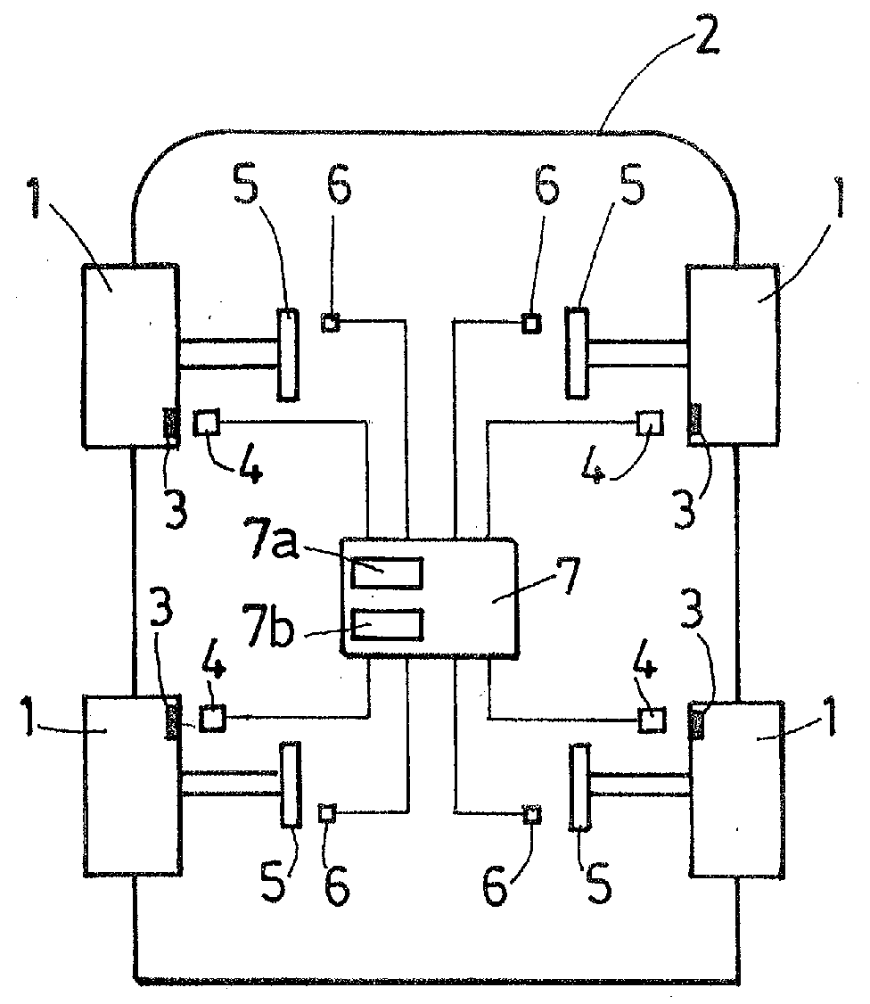
- the invention relates to a system for determining at least one parameter at least one rotating member 1 rotating relative to a fixed structure 2.
- this system is for determining at least one parameter of at least one tire 1 of a motor vehicle.
- the system allows the determination of the pressure, temperature, deformation and / or wear of all tires 1 of the vehicle.
- the system comprises, for each tire 1, a set comprising a transponder 3 able to measure the parameter (s) to determine, and a detection device 4 of the parameter (s) issued from the transponder 3.
- the transponder 3 is integral in rotation with the tire 1 and the detection device 4 is integral, in the vicinity of the transponder 3, the chassis 2 of the vehicle.
- the transponder 3 can be integral with the wheel or bearing on which the wheel is mounted.
- the determination system allows, by activating the detection device 4, periodically obtain the value of the parameter (s) measured by the transponder 3 and make this value available to a fixed system by relative to the chassis 2, for example vehicle safety, who controls it and / or used.
- the automatic determination of the parameter (s) may be used to warn the driver in the event of a fault.
- the Parameter (s) can be used in such driver assistance systems anti-lock wheels (ABS), trajectory control (ESP) or management assistance (DAE), so as to adapt the action of these systems according to the value of the determined parameters.
- the antenna is housed in the passage of the wheel on which is mounted the tire 1 and the transponder 3 is housed in the valve of the tire 1.
- the distance antenna - transponder 3 is reduced, which allows to optimize the electric power necessary for the communication of measurements between the tire 1 and the chassis 2.
- the transponder 3 is disposed in the tread of the tire 1, in particular to measure the deformation and wear of it.
- the assembly further comprises an encoder 5 integral in rotation with the tire 1 and a sensor 6 secured to the frame 2 of the vehicle.
- the encoder 5 and / or the sensor 6 can be arranged at the wheel bearing such that is for example described in document FR-2 700 588 issued by Applicant.
- the encoder 5 can in particular be secured in rotation to the rotating ring of the bearing and the sensor 6 can be associated with the fixed ring or dissociated from it, to be facing and reading distance from the encoder 5.
- the function of the encoder 5 is to deliver an angular position information of the 1.
- the encoder 5 is formed of a magnetic ring comprising on its surface a track formed of a succession of North poles and South.
- the senor 6 comprises an electronic circuit capable of delivering a signal representative of the angular position of the encoder 5 with respect to the frame 2.
- the senor 6 comprises at least two elements sensitive positioned next to the track.
- sensitive elements are selected from the group comprising the effect probes Hall, magnetoresistances, giant magnetoresistances.
- the sensor 6 used in this embodiment is capable of delivering two signals periodic electrical S1, S2 through quadrature elements sensitive. Moreover, the principle of obtaining signals S1 and S2 from of a plurality of aligned sensitive elements is for example described in the FR-2 792 403 from the applicant.
- the electronic circuit is capable of delivering digital signals of position A, B squares in quadrature which are representative of the angular position of the encoder but also of its rotational speed as well than its direction of rotation.
- the electronic circuit further comprises a interpolator, for example of the type described in document FR-2 754 063 issued of the plaintiff, allowing to increase the resolution of the signals of exit.
- a resolution of the angular position of the encoder 5 less than 1 ° can be obtained.
- the sensor 6 can be integrated on a silicon substrate or equivalent by example AsGa, so as to form an integrated circuit and customized for a specific application, circuit sometimes referred to as ASIC to make reference to the integrated circuit designed partially or completely according to needs.
- the encoder 5 may be formed of a metal or glass target on which the tracks main and top tower have been engraved so as to form an optical pattern analogous to the multipole magnetic motif set out above, the elements Sensors are then formed of optical detectors.
- the electronic circuit comprises counting means able to determine, from an initial position, the variations of the angular position of the encoder 5.
- the counting means comprise a register in which the value of the angular position is incremented or decremented by an angular value corresponding to the number of fronts signals A and B which are detected, the initial value being for example fixed at zero when commissioning the system.
- the treatment device allows to know the relative position of the encoder 5 relative to the initial position.
- the system includes a synchronization unit 7, in the form of a calculator, which is connected to each sensor 6 and to each detection device 4.
- the unit comprises a determination device 7a of an activation position of the detection device of a set when the transponder 3 of the set is in the transmit / receive cone of the antenna of said detection device, and an activation device 7b suitable, in comparing the position of the encoder to the activation position, to activate the device detection 4 to measure the parameter (s).
- Unit 7 makes it possible to synchronize the passage of transponder 3 in the cone with the activation of the detection device 4 so as to optimize the service life of the battery supplying the unit 7 and, as the case may be, of the battery supplying the transponder 3 in the case where it is active.
- the activation device 7b comprises means for resetting of the position signal of the encoder 5 with respect to the activation position, so as to deliver an absolute position signal of said encoder 5 with respect to said position, and therefore an absolute position signal of the tire 1 since the encoder 5 is integral in rotation thereof.
- a determination method using a system according to the invention comprises an initial procedure for determining an activation position, then when the position of the encoder 5 is equal to said activation position, the device active activation or allows activation of the detection device 4.
- the The method provides, after the determination of the activation position, the registration of the encoder position signal 5 with respect to said activation position, for, in, function of the coded position of the encoder, allow or allow the activation of the detection device 4.
- the activation device 7b When the activation device 7b allows the activation, it can be provided perform said activation at variable interrogation periods which are determined by the operating conditions of the tire.
- these conditions may be a function of the parameter (s) measured (pressure, temperature), vehicle running conditions such as that the speed or condition of the roadway (condition of rain or snow by example), positioning the tire 1 (front or rear).
- the synchronization unit 7 is also powered with the relevant parameters and with the desired conditions, said device including means for delaying the activation when the latter is authorized.
- the initial determination procedure can be performed by fixed frequency activation, for example every second, of the device 4 and, when the signal measured by the detection device 4 is satisfying, determining and recording in the activation device 7b of the activation position which is equal to the position of the encoder 5.
- This procedure is triggered each time the system is put into operation. determination, before the determination of the parameter (s) according to the invention.
- the optimization procedure may involve analyzing the quality of the signal from the detection device 4, for example its signal-to-noise ratio, the rate communication error, the power communicated. If this quality is less than a first threshold, incrementing and / or decrementing by a given step, for example one degree, the activation position. Iteratively, the procedure allows, by analyzing the quality of the corresponding signal, to increment or decrement the activation position to obtain an activation position optimized in which the signal quality is maximum. This position Optimized is used later as a new activation position.
- a second threshold of signal quality is used in the synchronization unit 7. if the signal quality is below the second threshold, procedure for determining an activation position in place of the optimization procedure.
- this embodiment makes it possible, in case of power supply to the system during the determination of the parameter (s), to initiate a determination procedure to reset the synchronization.
- this achievement also makes it possible start a determination procedure during optimization.
Landscapes
- Engineering & Computer Science (AREA)
- Mechanical Engineering (AREA)
- Arrangements For Transmission Of Measured Signals (AREA)
- Measuring Fluid Pressure (AREA)
- Measurement Of Length, Angles, Or The Like Using Electric Or Magnetic Means (AREA)
Abstract
L'invention concerne un système de détermination d'au moins un paramètre
d'au moins un organe tournant (1) par rapport à une structure fixe (2),
comprenant, pour chaque organe tournant (1), un ensemble comprenant un
transpondeur (3), un codeur (5), un capteur (6) de position, un dispositif de
détection (4) du ou des paramètre(s) issu(s) du transpondeur (3) ; ledit système
comprenant en outre une unité de synchronisation (7) qui est connectée à
chaque capteur (6) et à chaque dispositif de détection (4), ladite unité
comprenant un dispositif de détermination (7a) d'une position d'activation du
dispositif de détection (4) d'un ensemble lorsque le transpondeur (3) de
l'ensemble est dans le cône d'émission/réception du moyen de communication
dudit dispositif de détection, et un dispositif d'activation (7b) apte, en comparant
la position du codeur (5) à la position d'activation, à activer le dispositif de
détection (4) de l'ensemble pour mesurer le ou les paramètre(s).
Description
L'invention concerne un système de détermination d'au moins un paramètre d'au moins un organe tournant par rapport à une structure fixe, un procédé de détermination d'au moins un tel paramètre ainsi qu'un véhicule automobile comprenant un tel système.The invention relates to a system for determining at least one parameter of at least one rotating member with respect to a fixed structure, a method of determination of at least one such parameter as well as a motor vehicle including such a system.
L'invention s'applique typiquement à la détermination d'au moins un paramètre, tel que la pression, la température, la déformation, l'usure, d'un pneu de véhicule automobile.The invention typically applies to the determination of at least one parameter, such as the pressure, temperature, deformation and wear of a tire of motor vehicle.
Pour ce faire, il est connu d'utiliser pour chaque pneu :
- un transpondeur qui est solidaire en rotation du pneu, ledit transpondeur étant apte à mesurer le ou les paramètre(s) ; et
- un dispositif de détection du ou des paramètre(s) issu(s) du transpondeur, ledit dispositif étant solidaire du châssis du véhicule et comprenant une antenne apte à émettre un signal d'excitation au transpondeur et à recevoir la ou les mesure(s).
- a transponder which is integral in rotation with the tire, said transponder being able to measure the parameter (s); and
- a device for detecting the parameter (s) derived from the transponder, said device being integral with the vehicle chassis and comprising an antenna capable of transmitting an excitation signal to the transponder and receiving the measurement (s) .
Pour permettre la communication entre le transpondeur et le dispositif de détection, l'antenne de ce dernier est positionnée à proximité de la zone de déplacement du transpondeur, typiquement dans le passage de roue.To enable communication between the transponder and the detection, the antenna of the latter is positioned near the area of moving the transponder, typically in the wheel well.
Ainsi, en activant le dispositif de détection, il est possible d'obtenir périodiquement la valeur du ou des paramètre(s) mesuré(s) par le transpondeur et de rendre disponible cette valeur à un système, par exemple de sécurité du véhicule, qui la contrôle et/ou l'utilise.Thus, by activating the detection device, it is possible to obtain periodically the value of the parameter (s) measured by the transponder and make this value available to a system, for example security of the vehicle, who controls it and / or uses it.
Un problème qui se pose concerne l'établissement d'une procédure d'activation du dispositif de détection qui permette d'obtenir une communication satisfaisante entre ledit dispositif et le transpondeur. En effet, l'antenne présentant un cône d'émission/réception donné, l'activation doit être réalisée lorsque le transpondeur se trouve dans ce cône.A problem that arises is the establishment of an activation procedure of the detection device which makes it possible to obtain a communication satisfactory between said device and the transponder. Indeed, the antenna with a given transmit / receive cone, activation must be performed when the transponder is in this cone.
Selon une première solution, on a proposé d'activer le dispositif de détection en continu, mais celle-ci présente plusieurs inconvénients. Tout d'abord, elle induit une consommation électrique importante, et en partie inutile lorsque le transpondeur ne se trouve pas dans le cône d'émission/réception. En outre, elle sollicite le transpondeur à chaque rotation, ce qui, dans certaines conditions de roulage, est inutile et, dans le cas d'un transpondeur actif, consomme l'énergie de sa batterie inutilement.According to a first solution, it has been proposed to activate the detection device by continuous, but this has several disadvantages. First, it induces significant power consumption, and partly unnecessary when the transponder is not in the transmit / receive cone. In addition, she requests the transponder at each rotation, which, under certain conditions of is unnecessary and, in the case of an active transponder, consumes the energy of his battery unnecessarily.
Pour tenter de limiter la consommation électrique, on a proposé selon une deuxième solution d'activer à fréquence fixe le dispositif de détection. Mais cette solution présente également plusieurs inconvénients. Tout d'abord, elle ne permet pas d'assurer que le transpondeur soit dans le cône d'émission/réception lorsque le dispositif de détection est activé. En particulier, pour une fréquence d'activation donnée, il existe des vitesses de rotation du transpondeur pour lesquelles cette condition n'est pas remplie, ce qui est incompatible avec une utilisation du ou des paramètre(s) dans une fonction de sécurité du véhicule. En outre, cette solution ne permet pas de garantir une détermination du ou des paramètre(s) à fréquence donnée, par exemple en fonction de conditions de fonctionnement du véhicule.In an attempt to limit power consumption, it has been proposed second solution to activate fixed frequency detection device. But this solution also has several disadvantages. First, she does not does not ensure that the transponder is in the cone transmission / reception when the detection device is activated. In particular, for a given activation frequency, there are rotation speeds of the transponder for which this condition is not fulfilled, which is incompatible with a use of the parameter (s) in a function of vehicle safety. In addition, this solution does not guarantee a determination of the parameter (s) at a given frequency, for example in depending on the operating conditions of the vehicle.
Pour tenter de résoudre les inconvénients de cette deuxième solution, on a proposé d'augmenter la taille de l'antenne, de sorte à augmenter le cône d'émission/réception correspondant. Mais, outre que cette possibilité ne peut que limiter ces inconvénients sans les résoudre complètement puisque qu'une zone d'ombre dans la communication est toujours présente, l'augmentation de la taille de l'antenne induit des contraintes d'intégration accrues dans le passage de roue ainsi qu'une puissance et donc une consommation électrique plus importante.To try to solve the disadvantages of this second solution, we have proposed to increase the size of the antenna, so as to increase the cone corresponding transmission / reception. But, besides this possibility can not that limit these disadvantages without solving them completely since a shadow zone in communication is still present, the increase of the size of the antenna induces increased integration constraints in the passage wheel as well as power and therefore more power consumption important.
Pour résoudre l'ensemble de ces inconvénients, l'invention propose notamment un système de détermination qui permette de synchroniser la communication entre l'antenne et le transpondeur lorsque celui-ci est dans le cône d'émission/réception, de sorte à sécuriser la communication en optimisant la consommation électrique, et ce tout en pouvant adapter la fréquence de communication à des conditions de fonctionnement du véhicule. To solve all these disadvantages, the invention proposes in particular a system of determination which makes it possible to synchronize the communication between the antenna and the transponder when it is in the cone transmission / reception, so as to secure communication by optimizing electricity consumption, while being able to adapt the frequency of communication to the operating conditions of the vehicle.
A cet effet, et selon un premier aspect, l'invention propose un système de détermination d'au moins un paramètre d'au moins un organe tournant par rapport à une structure fixe, ledit système comprenant, pour chaque organe tournant, un ensemble comprenant :
- un transpondeur solidaire en rotation de l'organe tournant, ledit transpondeur étant apte à mesurer le ou les paramètre(s) à déterminer ;
- un codeur solidaire en rotation de l'organe tournant ;
- un capteur solidaire de la structure fixe, ledit capteur étant disposé en regard et à distance de lecture du codeur, ledit capteur comprenant un circuit électronique apte à délivrer un signal représentatif de la position angulaire du codeur par rapport à la structure fixe ;
- un dispositif de détection du ou des paramètre(s) issu(s) du transpondeur, ledit dispositif étant solidaire de la structure fixe et comprenant un moyen de communication apte à émettre un signal d'excitation au transpondeur et à recevoir la ou les mesure(s) ;
une unité de synchronisation qui est connectée à chaque capteur et à chaque dispositif de détection, ladite unité comprenant un dispositif de détermination d'une position d'activation du dispositif de détection d'un ensemble lorsque le transpondeur de l'ensemble est dans le cône d'émission/réception du moyen de communication dudit dispositif de détection, et un dispositif d'activation apte, en comparant la position du codeur à la position d'activation, à activer le dispositif de détection de l'ensemble pour mesurer le ou les paramètre(s).For this purpose, and according to a first aspect, the invention proposes a system for determining at least one parameter of at least one rotating member with respect to a fixed structure, said system comprising, for each rotating member, an assembly comprising :
- a transponder integral in rotation with the rotating member, said transponder being able to measure the parameter (s) to be determined;
- an encoder integral in rotation with the rotating member;
- a sensor secured to the fixed structure, said sensor being arranged opposite and at a reading distance from the encoder, said sensor comprising an electronic circuit capable of delivering a signal representative of the angular position of the encoder relative to the fixed structure;
- a device for detecting the parameter (s) derived from the transponder, said device being integral with the fixed structure and comprising a communication means able to transmit an excitation signal to the transponder and to receive the measurement or measurements ( s);
a synchronization unit which is connected to each sensor and to each detection device, said unit comprising a device for determining an activation position of the detection device of an assembly when the transponder of the assembly is in the cone transmission / reception of the communication means of said detection device, and an activation device adapted, by comparing the position of the encoder to the activation position, to activate the detection device of the assembly for measuring the one or more settings).
Dans un mode de réalisation, le dispositif d'activation comprend des moyens de recalage du signal de position du codeur par rapport à la position d'activation.In one embodiment, the activation device comprises means for resetting of the encoder position signal with respect to the activation position.
Selon un deuxième aspect, l'invention propose un procédé de détermination d'au moins un paramètre d'au moins un organe tournant par rapport à une structure fixe au moyen d'un tel système, comprenant une procédure initiale de détermination d'une position d'activation, puis lorsque la position du codeur est égale à ladite position d'activation, le dispositif d'activation active ou autorise l'activation du dispositif de détection. According to a second aspect, the invention proposes a determination method of at least one parameter of at least one rotating member with respect to a fixed structure by means of such a system, including an initial procedure of determining an activation position and then when the encoder position is equal to said activation position, the activation device activates or authorizes activation of the detection device.
Dans une réalisation particulière, lorsque le dispositif d'activation comprend des moyens de recalage, le procédé de détermination comprend une procédure initiale de détermination d'une position d'activation, après laquelle le signal de position du codeur est recalé par rapport à ladite position d'activation, pour, en fonction de la position recalée du codeur, permettre ou autoriser l'activation du dispositif de détection.In a particular embodiment, when the activation device comprises resetting means, the determination method comprises a procedure initial determination of an activation position, after which the signal of position of the encoder is recalibrated with respect to said activation position, for, in function of the coded position of the encoder, allow or allow the activation of the detection device.
Selon un troisième aspect, l'invention propose un véhicule automobile comprenant un tel système, chaque ensemble étant disposé de sorte à déterminer au moins un paramètre d'un pneu dudit véhicule.According to a third aspect, the invention proposes a motor vehicle comprising such a system, each set being arranged so as to determine at least one parameter of a tire of said vehicle.
D'autres objets et avantages de l'invention apparaítront au cours de la description qui suit, faite en référence au dessin annexé qui représente de façon schématique un véhicule comprenant un système de détermination selon l'invention.Other objects and advantages of the invention will appear during the description which follows, made with reference to the attached drawing which represents schematic a vehicle comprising a determination system according to the invention.
L'invention concerne un système de détermination d'au moins un paramètre
d'au moins un organe tournant 1 en rotation par rapport à une structure fixe 2.
Selon le mode de réalisation décrit en relation avec la figure, ce système est
destiné à la détermination d'au moins un paramètre d'au moins un pneu 1 d'un
véhicule automobile. En particulier, le système permet la détermination de la
pression, de la température, de la déformation et/ou de l'usure de tous les
pneus 1 du véhicule.The invention relates to a system for determining at least one parameter
at least one rotating member 1 rotating relative to a
Pour ce faire, le système comprend, pour chaque pneu 1, un ensemble
comprenant un transpondeur 3 apte à mesurer le ou les paramètre(s) à
déterminer, et un dispositif de détection 4 du ou des paramètre(s) issu(s) du
transpondeur 3. Le transpondeur 3 est solidaire en rotation du pneu 1 et le
dispositif de détection 4 est solidaire, au voisinage du transpondeur 3, du
châssis 2 du véhicule. Selon d'autres applications, le transpondeur 3 peut être
solidaire de la roue ou du roulement sur lequel la roue est montée.To do this, the system comprises, for each tire 1, a set
comprising a
Le système de détermination permet, en activant le dispositif de détection 4,
d'obtenir périodiquement la valeur du ou des paramètre(s) mesuré(s) par le
transpondeur 3 et de rendre disponible cette valeur à un système fixe par
rapport au châssis 2, par exemple de sécurité du véhicule, qui la contrôle et/ou
l'utilise. En particulier, la détermination automatique du ou des paramètre(s)
peut permettre d'avertir le conducteur en cas d'anomalie. En outre, le ou les
paramètre(s) peuvent être utilisés dans des systèmes d'aide à la conduite tels
que l'anti-blocage des roues (ABS), le contrôle de la trajectoire (ESP) ou
l'assistance électrique de la direction (DAE), de sorte à adapter l'action de ces
systèmes en fonction de la valeur des paramètres déterminés.The determination system allows, by activating the
Un ensemble transpondeur 3 - dispositif de détection 4 est connu de l'art antérieur :
- le dispositif de
détection 4 comprenant un moyen de communication, par exemple sous la forme d'une antenne directionnelle, apte à émettre un signal d'excitation, par exemple RF, autranspondeur 3 et à recevoir la ou les mesure(s) ; et - le
transpondeur 3 pouvant être de type actif ou de type passif suivant qu'il est alimenté par une batterie propre afin d'effectuer la mesure et la communication ou que ces fonctions sont induites par le signal d'excitation issu du dispositif dedétection 4. Pour la détermination de la pression du pneu 1, letranspondeur 3 peut être du type à ondes acoustiques de surface (SAW).
- the
detection device 4 comprising a communication means, for example in the form of a directional antenna, capable of transmitting an excitation signal, for example RF, to thetransponder 3 and receiving the measurement (s); and - the
transponder 3 can be of active type or of passive type depending on whether it is powered by a clean battery in order to carry out the measurement and the communication or that these functions are induced by the excitation signal coming from thedetection device 4. For the determination of the tire pressure 1, thetransponder 3 may be of the SAW type.
Dans le véhicule suivant l'invention, l'antenne est logée dans le passage de la
roue sur laquelle est monté le pneu 1 et le transpondeur 3 est logé dans la valve
du pneu 1. Ainsi la distance antenne - transpondeur 3 est réduite, ce qui permet
d'optimiser la puissance électrique nécessaire à la communication des mesures
entre le pneu 1 et le châssis 2. En variante, on peut également prévoir que le
transpondeur 3 soit disposé dans la bande de roulement du pneu 1, notamment
pour mesurer la déformation et l'usure de celui-ci.In the vehicle according to the invention, the antenna is housed in the passage of the
wheel on which is mounted the tire 1 and the
L'ensemble comprend en outre un codeur 5 solidaire en rotation du pneu 1 et un
capteur 6 solidaire du châssis 2 du véhicule. En particulier, le codeur 5 et/ou le
capteur 6 peuvent être disposés au niveau du roulement de la roue tel que cela
est par exemple décrit dans le document FR-2 700 588 issu de la
demanderesse. Le codeur 5 peut en particulier être solidarisé en rotation à la
bague tournante du roulement et le capteur 6 peut être associé à la bague fixe
ou dissocié de celle-ci, pour être en regard et à distance de lecture du codeur 5.The assembly further comprises an
Le codeur 5 a pour fonction de délivrer une information de position angulaire du
pneu 1. Suivant une réalisation, le codeur 5 est formé d'un anneau magnétique
comprenant sur sa surface une piste formée d'une succession de pôles Nord et
Sud.The function of the
En regard et à distance de lecture de ce codeur 5, est prévu le capteur 6 qui
comprend un circuit électronique apte à délivrer un signal représentatif de la
position angulaire du codeur 5 par rapport au châssis 2.In view of and at a distance from reading of this
Suivant une réalisation, le capteur 6 comprend au moins deux éléments
sensibles positionnés en regard de la piste. Dans un exemple particulier, les
éléments sensibles sont choisis dans le groupe comprenant les sondes à effet
Hall, les magnétorésistances, les magnétorésistances géantes.According to one embodiment, the
Le capteur 6 utilisé dans cette réalisation est apte à délivrer deux signaux
électriques S1, S2 périodiques en quadrature par l'intermédiaire des éléments
sensibles. Par ailleurs, le principe d'obtention des signaux S1 et S2 à partir
d'une pluralité d'éléments sensibles alignés est par exemple décrit dans le
document FR-2 792 403 issu de la demanderesse.The
A partir des signaux S1, S2, le circuit électronique est apte à délivrer des signaux digitaux de position A, B carrés en quadrature qui sont représentatifs de la position angulaire du codeur mais également de sa vitesse de rotation ainsi que de son sens de rotation.From the signals S1, S2, the electronic circuit is capable of delivering digital signals of position A, B squares in quadrature which are representative of the angular position of the encoder but also of its rotational speed as well than its direction of rotation.
Suivant une réalisation, le circuit électronique comprend en outre un
interpolateur, par exemple du type décrit dans le document FR-2 754 063 issu
de la demanderesse, permettant d'augmenter la résolution des signaux de
sortie. En particulier, une résolution de la position angulaire du codeur 5
inférieure à 1° peut être obtenue. According to one embodiment, the electronic circuit further comprises a
interpolator, for example of the type described in document FR-2 754 063 issued
of the plaintiff, allowing to increase the resolution of the signals of
exit. In particular, a resolution of the angular position of the
Le capteur 6 peut être intégré sur un substrat en silicium ou équivalent par
exemple AsGa, de sorte à former un circuit intégré et personnalisé pour une
application spécifique, circuit parfois désigné sous le terme ASIC pour faire
référence au circuit intégré conçu partiellement ou complètement en fonction
des besoins.The
Bien que la description soit faite en relation avec un ensemble codeur/capteur
magnétique, il est également possible de mettre en oeuvre l'invention de façon
analogue en utilisant une technologie de type optique. Par exemple, le codeur 5
peut être formé d'une cible en métal ou en verre sur laquelle les pistes
principale et top tour ont été gravées de sorte à former un motif optique
analogue au motif magnétique multipolaire exposé ci-dessus, les éléments
sensibles étant alors formés de détecteurs optiques.Although the description is made in connection with an encoder / sensor assembly
magnetic, it is also possible to implement the invention so
analog using optical technology. For example, the
Le circuit électronique comprend des moyens de comptage aptes à déterminer,
à partir d'une position initiale, les variations de la position angulaire du codeur 5.
Dans un exemple de réalisation, les moyens de comptage comprennent un
registre dans lequel la valeur de la position angulaire est incrémentée ou
décrémentée d'une valeur angulaire correspondant au nombre de fronts des
signaux A et B qui sont détectés, la valeur initiale étant par exemple fixée à zéro
lors de la mise en service du système. Ainsi, le dispositif de traitement permet
de connaítre la position relative du codeur 5 par rapport à la position initiale.The electronic circuit comprises counting means able to determine,
from an initial position, the variations of the angular position of the
Outre le ou les ensemble(s), le système comprend une unité de synchronisation
7, sous la forme d'un calculateur, qui est connecté à chaque capteur 6 et à
chaque dispositif de détection 4. L'unité comprend un dispositif de détermination
7a d'une position d'activation du dispositif de détection d'un ensemble lorsque le
transpondeur 3 de l'ensemble est dans le cône d'émission/réception de
l'antenne dudit dispositif de détection, et un dispositif d'activation 7b apte, en
comparant la position du codeur à la position d'activation, à activer le dispositif
de détection 4 pour mesurer le ou les paramètre(s). In addition to the assembly (s), the system includes a synchronization unit
7, in the form of a calculator, which is connected to each
L'unité 7 permet de synchroniser le passage du transpondeur 3 dans le cône
avec l'activation du dispositif de détection 4 de sorte à optimiser la durée de vie
de la batterie alimentant l'unité 7 et, le cas échéant, de la batterie alimentant le
transpondeur 3 dans le cas où celui-ci est actif.Unit 7 makes it possible to synchronize the passage of
Selon une réalisation, le dispositif d'activation 7b comprend des moyens de
recalage du signal de position du codeur 5 par rapport à la position d'activation,
de sorte à délivrer un signal de position absolue dudit codeur 5 par rapport à
ladite position, et donc un signal de position absolue du pneu 1 puisque le
codeur 5 est solidaire en rotation de celui-ci.According to one embodiment, the
Un procédé de détermination utilisant un système suivant l'invention, comprend
une procédure initiale de détermination d'une position d'activation, puis lorsque
la position du codeur 5 est égale à ladite position d'activation, le dispositif
d'activation active ou autorise l'activation du dispositif de détection 4.A determination method using a system according to the invention comprises
an initial procedure for determining an activation position, then when
the position of the
Lorsque le dispositif de d'activation 7b comprend des moyens de recalage, le
procédé prévoit, après la détermination de la position d'activation, le recalage du
signal de position du codeur 5 par rapport à ladite position d'activation, pour, en
fonction de la position recalée du codeur, permettre ou autoriser l'activation du
dispositif de détection 4.When the
Lorsque le dispositif d'activation 7b autorise l'activation, il peut être prévu de
réaliser ladite activation à des périodes d'interrogation variables qui sont
déterminées en fonction des conditions de fonctionnement du pneu 1. En
particulier, ces conditions peuvent être fonction du ou des paramètre(s)
mesuré(s) (pression, température), des conditions de roulage du véhicule telles
que la vitesse ou l'état de la chaussée (condition de pluie ou de neige par
exemple), du positionnement du pneu 1 (avant ou arrière).When the
Dans un exemple de réalisation, on peut définir au moins un seuil de vitesse pour le véhicule de sorte que :
- en dessous du seuil, l'activation soit réalisée à une fréquence fi;
- au dessus du seuil, l'activation soit réalisée à une fréquence multiple de fi.
- below the threshold, the activation is performed at a frequency f i ;
- above the threshold, the activation is performed at a frequency of multiple f i .
On peut également décider de déterminer la pression des pneus 1 arrières plus fréquemment que celle des pneus avants.One can also decide to determine the tire pressure 1 more rear tires frequently as that of the front tires.
Pour ce faire, l'unité de synchronisation 7 est également alimenté avec les paramètres pertinents et avec les conditions souhaitées, ledit dispositif comprenant des moyens de temporisation de l'activation lorsque celle-ci est autorisée.To do this, the synchronization unit 7 is also powered with the relevant parameters and with the desired conditions, said device including means for delaying the activation when the latter is authorized.
Selon une réalisation, la procédure initiale de détermination peut être réalisée
par activation à fréquence fixe, par exemple toutes les secondes, du dispositif
de détection 4 et, lorsque le signal mesuré par le dispositif de détection 4 est
satisfaisant, détermination et enregistrement dans le dispositif d'activation 7b de
la position d'activation qui est égale à la position du codeur 5.According to one embodiment, the initial determination procedure can be performed
by fixed frequency activation, for example every second, of the
Cette procédure est déclenchée à chaque mise en service du système de détermination, avant la détermination du ou des paramètre(s) suivant l'invention.This procedure is triggered each time the system is put into operation. determination, before the determination of the parameter (s) according to the invention.
Suivant une réalisation, on peut prévoir une procédure itérative d'optimisation de la position d'activation, ladite procédure pouvant être déclenchée en continu ou de façon périodique.According to one embodiment, it is possible to provide an iterative procedure for optimizing the activation position, which procedure can be triggered continuously or periodically.
La procédure d'optimisation peut prévoir d'analyser la qualité du signal issu du
dispositif de détection 4, par exemple son rapport signal sur bruit, le taux
d'erreur de communication, la puissance communiquée. Si cette qualité est
inférieure à un premier seuil, incrémenter et/ou décrémenter d'un pas donné,
par exemple d'un degré, la position d'activation. De façon itérative, la procédure
permet, en analysant la qualité du signal correspondant, d'incrémenter ou de
décrémenter la position d'activation pour obtenir une position d'activation
optimisée dans laquelle la qualité du signal est maximale. Cette position
optimisée est utilisée ultérieurement en tant que nouvelle position d'activation.The optimization procedure may involve analyzing the quality of the signal from the
Suivant une réalisation du procédé, un deuxième seuil de qualité du signal, inférieur au premier, est utilisé dans l'unité de synchronisation 7. On peut ainsi prévoir, si la qualité du signal est inférieure au deuxième seuil, de déclencher la procédure de détermination d'une position d'activation à la place de la procédure d'optimisation. En particulier, cette réalisation permet, en cas de coupure d'alimentation électrique du système lors de la détermination du ou des paramètre(s), de lancer une procédure de détermination pour recaler la synchronisation. En outre, si la procédure d'optimisation ne permet pas de converger vers une position optimisée, cette réalisation permet également de lancer une procédure de détermination en cours d'optimisation.According to one embodiment of the method, a second threshold of signal quality, less than the first, is used in the synchronization unit 7. if the signal quality is below the second threshold, procedure for determining an activation position in place of the optimization procedure. In particular, this embodiment makes it possible, in case of power supply to the system during the determination of the parameter (s), to initiate a determination procedure to reset the synchronization. In addition, if the optimization procedure does not allow converge towards an optimized position, this achievement also makes it possible start a determination procedure during optimization.
Claims (11)
Applications Claiming Priority (2)
| Application Number | Priority Date | Filing Date | Title |
|---|---|---|---|
| FR0350881A FR2862822B1 (en) | 2003-11-21 | 2003-11-21 | SYSTEM AND METHOD FOR DETERMINING AT LEAST ONE PARAMETER OF AT LEAST ONE ROTATING ORGAN BY MEANS OF A POSITION SIGNAL |
| FR0350881 | 2003-11-21 |
Publications (1)
| Publication Number | Publication Date |
|---|---|
| EP1533147A2 true EP1533147A2 (en) | 2005-05-25 |
Family
ID=34430108
Family Applications (1)
| Application Number | Title | Priority Date | Filing Date |
|---|---|---|---|
| EP04292636A Withdrawn EP1533147A2 (en) | 2003-11-21 | 2004-11-08 | System and process for the determination of the position of at least a rotating part by use of a position signal |
Country Status (4)
| Country | Link |
|---|---|
| US (1) | US7196615B2 (en) |
| EP (1) | EP1533147A2 (en) |
| JP (1) | JP2005158054A (en) |
| FR (1) | FR2862822B1 (en) |
Cited By (1)
| Publication number | Priority date | Publication date | Assignee | Title |
|---|---|---|---|---|
| CN115711752A (en) * | 2022-11-04 | 2023-02-24 | 广州小鹏汽车科技有限公司 | Tire wear detection method, device, vehicle and computer-readable storage medium |
Families Citing this family (9)
| Publication number | Priority date | Publication date | Assignee | Title |
|---|---|---|---|---|
| DE10331314B3 (en) * | 2003-07-10 | 2004-06-17 | Siemens Ag | Position locating method for transmitters of tire pressure or temperature monitors for automobile wheels |
| DE102004034875A1 (en) * | 2004-07-19 | 2006-03-16 | Siemens Ag | Device for locating a wheel electronics in a motor vehicle |
| JP4289561B2 (en) * | 2004-12-24 | 2009-07-01 | 横浜ゴム株式会社 | Vehicle abnormality detection method and apparatus, and sensor unit thereof |
| US20060206247A1 (en) * | 2005-03-09 | 2006-09-14 | Trw Automotive U.S. Llc | Tire parameter sensing system having a tire-based unit that is responsive to a trigger signal and associated method |
| KR101704061B1 (en) * | 2011-12-01 | 2017-02-08 | 현대자동차주식회사 | Method and apparatus for auto-learning position of tire for tpms system |
| FR3067137A1 (en) * | 2017-06-02 | 2018-12-07 | Compagnie Generale Des Etablissements Michelin | METHOD FOR PROVIDING A SERVICE RELATED TO THE STATE AND / OR BEHAVIOR OF A VEHICLE AND / OR A TIRE |
| WO2020217294A1 (en) * | 2019-04-23 | 2020-10-29 | 三菱電機株式会社 | Wireless communication device and wireless communication method |
| FR3120207A1 (en) * | 2021-02-26 | 2022-09-02 | Continental Automotive Gmbh | Method for locating the wheels of a motor vehicle |
| WO2022258202A1 (en) * | 2021-06-11 | 2022-12-15 | Volvo Truck Corporation | A electronic control unit (ecu) and method therein for monitoring tire sensors in a vehicle |
Citations (3)
| Publication number | Priority date | Publication date | Assignee | Title |
|---|---|---|---|---|
| FR2700588A1 (en) | 1993-01-19 | 1994-07-22 | Roulements Soc Nouvelle | Mounting device with integrated encoder seal. |
| FR2754063A1 (en) | 1996-09-30 | 1998-04-03 | Roulements Soc Nouvelle | CIRCUIT FOR MULTIPLICATION OF RESOLUTION AND DETERMINATION OF MEANS OF MOVEMENT |
| FR2792403A1 (en) | 1999-04-14 | 2000-10-20 | Roulements Soc Nouvelle | POSITION AND / OR DISPLACEMENT SENSOR COMPRISING A PLURALITY OF ALIGNED SENSITIVE ELEMENTS |
Family Cites Families (15)
| Publication number | Priority date | Publication date | Assignee | Title |
|---|---|---|---|---|
| JPH0436613A (en) * | 1990-06-01 | 1992-02-06 | Yamaha Corp | Magnetic rotary encoder |
| DE19618658A1 (en) * | 1996-05-09 | 1997-11-13 | Continental Ag | Air pressure control system |
| EP0832765B1 (en) * | 1996-09-27 | 2003-05-28 | Motorola, Inc. | Tyre pressure monitoring system |
| DE19734323B4 (en) * | 1997-08-08 | 2004-05-06 | Continental Aktiengesellschaft | Method for carrying out the assignment of the wheel position to tire pressure control devices in a tire pressure control system of a motor vehicle |
| US6591671B2 (en) * | 1999-08-16 | 2003-07-15 | The Goodyear Tire & Rubber Company | Monitoring pneumatic tire conditions |
| US6278363B1 (en) * | 2000-07-14 | 2001-08-21 | Motorola, Inc | Method and system for monitoring air pressure of tires on a vehicle |
| CA2676101C (en) * | 2000-07-26 | 2016-12-06 | Bridgestone/Firestone, Inc. | Electronic tire management system |
| US6362731B1 (en) * | 2000-12-06 | 2002-03-26 | Eaton Corporation | Tire pressure monitor and location identification system and method |
| DE10135936B4 (en) * | 2001-07-24 | 2005-01-05 | Siemens Ag | Device for monitoring at least one parameter for several vehicle wheels |
| FR2832531B1 (en) * | 2001-11-20 | 2004-01-02 | Siemens Vdo Automotive | METHOD AND DEVICE FOR COMMUNICATING BETWEEN A VEHICLE WHEEL AND A COMPUTER PLACED IN THE VEHICLE |
| JP4000891B2 (en) * | 2002-04-12 | 2007-10-31 | トヨタ自動車株式会社 | Tire condition acquisition device |
| US7015802B2 (en) * | 2002-08-08 | 2006-03-21 | Forster Ian J | Vehicle tag reader |
| FR2844748B1 (en) * | 2002-09-25 | 2004-11-26 | Johnson Contr Automotive Elect | TIRE PRESSURE MONITORING SYSTEM FOR A MOTOR VEHICLE |
| JP3975973B2 (en) * | 2003-06-05 | 2007-09-12 | トヨタ自動車株式会社 | Wheel-body communication system |
| US7104438B2 (en) * | 2003-10-22 | 2006-09-12 | The Goodyear Tire & Rubber Company | Method of integrating tire identification into a vehicle information system |
-
2003
- 2003-11-21 FR FR0350881A patent/FR2862822B1/en not_active Expired - Fee Related
-
2004
- 2004-10-29 JP JP2004316880A patent/JP2005158054A/en active Pending
- 2004-11-08 EP EP04292636A patent/EP1533147A2/en not_active Withdrawn
- 2004-11-08 US US10/982,815 patent/US7196615B2/en not_active Expired - Fee Related
Patent Citations (3)
| Publication number | Priority date | Publication date | Assignee | Title |
|---|---|---|---|---|
| FR2700588A1 (en) | 1993-01-19 | 1994-07-22 | Roulements Soc Nouvelle | Mounting device with integrated encoder seal. |
| FR2754063A1 (en) | 1996-09-30 | 1998-04-03 | Roulements Soc Nouvelle | CIRCUIT FOR MULTIPLICATION OF RESOLUTION AND DETERMINATION OF MEANS OF MOVEMENT |
| FR2792403A1 (en) | 1999-04-14 | 2000-10-20 | Roulements Soc Nouvelle | POSITION AND / OR DISPLACEMENT SENSOR COMPRISING A PLURALITY OF ALIGNED SENSITIVE ELEMENTS |
Cited By (1)
| Publication number | Priority date | Publication date | Assignee | Title |
|---|---|---|---|---|
| CN115711752A (en) * | 2022-11-04 | 2023-02-24 | 广州小鹏汽车科技有限公司 | Tire wear detection method, device, vehicle and computer-readable storage medium |
Also Published As
| Publication number | Publication date |
|---|---|
| FR2862822B1 (en) | 2006-02-03 |
| US7196615B2 (en) | 2007-03-27 |
| JP2005158054A (en) | 2005-06-16 |
| US20050110624A1 (en) | 2005-05-26 |
| FR2862822A1 (en) | 2005-05-27 |
Similar Documents
| Publication | Publication Date | Title |
|---|---|---|
| EP1593532B1 (en) | System for controlling the tyre pressure of a motor vehicle | |
| EP1743151B1 (en) | Deformation-sensing bearing comprising four stress gauges | |
| FR2924518A1 (en) | DEVICE FOR LOCATING THE RIGHT AND LEFT POSITION OF A PNEUMATIC ASSEMBLY AND WHEEL OF A VEHICLE | |
| FR2856142A1 (en) | DETERMINATION OF THE ABSOLUTE ANGULAR POSITION OF A STEERING WHEEL BY INCREMENTAL MEASUREMENT AND MEASUREMENT OF THE DIFFERENTIAL WHEEL SPEED | |
| EP1403622A1 (en) | Absolute angle sensor | |
| EP1533147A2 (en) | System and process for the determination of the position of at least a rotating part by use of a position signal | |
| EP2655102A1 (en) | Method for taking acceleration measurements of a wheel of a motor vehicle | |
| WO2016082933A1 (en) | Camshaft or crankshaft sensor for automotive vehicle and diagnostic method for such a sensor | |
| EP1882907A1 (en) | Method for the determination of two signals in quadrature | |
| EP1946059B1 (en) | Deformation-sensor bearing comprising at least three strain gauges | |
| EP1533148A1 (en) | System and process for determining at least one parameter of at least one rotating member by means of reference and speed signals | |
| WO2017059938A1 (en) | Wheel electronic unit and method of mounting same | |
| EP1631793B1 (en) | Determination of the absolute angular position of a steering wheel by binary sequences discrimination | |
| EP1533620B1 (en) | System and method for determining at least one parameter of at least one rotating unit using an absolute position signal | |
| EP1403621B1 (en) | Absolute angle sensor | |
| WO2019016455A1 (en) | Method for locating a position of each wheel of a motor vehicle associated with an electronic unit | |
| FR2879750A1 (en) | METHOD FOR DETERMINING THE ROTATION SENSE OF A WHEEL AND DEVICE USING THE SAME | |
| EP2523814B1 (en) | Method for exchanging signals between a tire pressure sensor and a central processing unit in a motor vehicle | |
| FR2919415A1 (en) | METHOD AND DEVICE FOR LOCATING THE WHEELS OF A VEHICLE | |
| WO2005121731A1 (en) | Bearing deformation sensor comprising two stress gauges | |
| FR2932878A1 (en) | Terrain inclination estimating device for four-wheel drive motor vehicle, has calculator providing inclination of terrain from instantaneous acceleration signals provided by accelerometers | |
| EP1882158B1 (en) | Reference pulse discrimination method | |
| FR3075753A1 (en) | ELECTRICAL DEVICE SOLIDARIZED TO A ROTATING SHAFT | |
| FR2949382A1 (en) | Tire pressure monitoring system for motor vehicle, has controllers establishing value indicative of angular speed of wheel from periodic signal issued by sensor and embarked on wheel, so that value of speed is transmitted to destination | |
| FR2936324A1 (en) | NAVIGATION METHOD AND SYSTEM IMPLEMENTING SUCH A METHOD |
Legal Events
| Date | Code | Title | Description |
|---|---|---|---|
| PUAI | Public reference made under article 153(3) epc to a published international application that has entered the european phase |
Free format text: ORIGINAL CODE: 0009012 |
|
| AK | Designated contracting states |
Kind code of ref document: A2 Designated state(s): AT BE BG CH CY CZ DE DK EE ES FI FR GB GR HU IE IS IT LI LU MC NL PL PT RO SE SI SK TR |
|
| AX | Request for extension of the european patent |
Extension state: AL HR LT LV MK YU |
|
| STAA | Information on the status of an ep patent application or granted ep patent |
Free format text: STATUS: THE APPLICATION IS DEEMED TO BE WITHDRAWN |
|
| 18D | Application deemed to be withdrawn |
Effective date: 20090603 |