FIELD OF THE INVENTION
The present invention relates to a recording position
correction method, an inkjet type recording apparatus and a
computer program therefor. More particularly, the present
invention relates to a recording position correction method,
an ink jet type recording apparatus and a computer program capable
of making up for the deviation of the recording position due
to the mounting direction of a recording head.
BACKGROUND ART
An inkjet type recording apparatus performs recording
on a medium to be recorded by ejecting ink from a plurality
of nozzles while allowing a carriage including a recording
head on which nozzle arrays consisting of a plurality of nozzles,
which are provided in a sub-scanning direction, are arranged
in a main scanning direction to perform a scanning operation
along at least either a forward or backward path in the main
scanning direction as disclosed, for example, in a Japanese
Patent Application Publication No. JPA 11-348250.
In the inkjet type recording apparatus, the carriage
might be mounted on a guide which is designed to support the
carriage while the carriage is angled with respect to the guide.
In addition, if the carriage is not mounted on the guide in
a good state, the carriage might cause so called a chattering
while the recording head performs scanning at least either
back or forth in the main scanning direction. If the recording
head is not positioned at exact accuracy with respect to the
medium to be recorded in the inkjet type recording apparatus,
it is impossible to perform desired recording.
DESCRIPTION OF THE INVENTION
Accordingly, it is an object of the present invention
to provide a recording position correction method, an inkjet
type recording apparatus and a computer program there for, which
is capable of overcoming the above drawbacks accompanying the
conventional apparatus or system. The above and other obj ects
can be achieved by combinations described in the independent
claims. The dependent claims define further advantageous and
exemplary combinations of the present invention.
In order to solve the problems above, according to the
first aspect of the present invention, a recording position
correction method for correcting position deviation in a
sub-scanning direction crossing a main scanning direction of
a recording position on a medium to be recorded, wherein an
inkjet type recording apparatus performs recording on the
medium to be recorded by ejecting ink from a plurality of nozzles
while allowing a recording head, on which nozzle arrays
including the plurality of nozzles provided in the sub-scanning
direction are arranged in the main scanning direction, to
perform scanning along at least one of forward and backward
paths in the main scanning direction, includes an ejection
step of ejecting the ink from the plurality of nozzles onto
the medium to be recorded, a measurement step of measuring
an amount of position deviation in the sub-scanning direction
of an ink dot recorded and a correction step of previously
shifting and correcting a recording position of an ink dot
to be recorded on the material for each of the plurality of
nozzles based on the measured amount of the position deviation.
The ink may be ejected from at least one nozzle of each
of two nozzle arrays most distanced from each other in the
main scanning direction among the plurality of nozzle arrays
in the ejection step, and the recording position of the ink
dot to be recorded on the material for each of the plurality
of nozzles may be previously shifted and corrected based on
an amount of position deviation of an ink dot ejected and recorded
from the nozzle of the two nozzle arrays in the correction
step.
The ink may be further ejected from a nozzle of a nozzle
array among the plurality of nozzle arrays except the two nozzle
arrays in the ejection step, and the recording position of
the ink dot to be recorded on the material for each of the
plurality of nozzles may be previously shifted and corrected
based on an amount of position deviation of an ink dot ejected
and recorded from at least one nozzle of each of the two nozzle
arrays and at least one nozzle of the nozzle array except the
two nozzle arrays in the correction step.
The ink may be ejected from the plurality of nozzles
in order that a color of the ink from each of the nozzle arrays
is different from one another in the ejection step, and the
recording position of the ink dot may be previously shifted
and corrected for each of the colors in the correction step.
The ink may be ejected while the recording head performs
scanning along the forward and/or backward path(s) in the main
scanning direction in the ejection step, and the recording
position of the ink dot may be previously shifted and corrected
in the correction step based on an intermediate value between
an amount of position deviation of an ink dot ejected and recorded
in case the ink is ejected while the recording head performs
scanning along the forward path in the main scanning direction
and an amount of position deviation of an ink dot ejected and
recorded in case the ink is ejected while the recording head
performs scanning along the backward path.
The ink may be ejected while the recording head performs
scanning along the forward and/or backward path (s) in the main
scanning direction in the ejection step, and the correction
may be performed in the correction step, wherein the recording
position of an ink dot to be recorded along the forward path
in the main scanning direction may be previously shifted based
on an amount of position deviation in case the recording head
performs scanning along the forward path in the main scanning
direction and the recording position of an ink dot to be recorded
along the backward path may be previously shifted based on
an amount of position deviation in case the recording head
performs scanning along the backward path.
The ink may be ejected from at least one nozzle of each
of two nozzle arrays which eject the ink of two colors
respectively among the plurality of nozzle arrays as priority
is given to a color of which density is highest in the ejection
step, and the recording position of the ink dot to be recorded
on the material for each of the plurality of nozzles may be
previously shifted and corrected based on an amount of position
deviation of an ink dot ejected and recorded from the nozzle
of the two nozzle arrays in the correction step.
According to the second aspect of the present invention,
an inkjet type recording apparatus for performing recording
on the medium to be recorded by ejecting ink from a plurality
of nozzles while allowing a recording head, on which nozzle
arrays including the plurality of nozzles provided in the
sub-scanning direction are arranged in the main scanning
direction, to perform scanning along at least one of forward
and backward paths in the main scanning direction, includes
a correcting unit for previously shifting and correcting a
recording position of an ink dot to be recorded on the material
for each of the plurality of nozzles based on an amount of
position deviation in a sub-scanning direction crossing the
main scanning direction of an ink dot ejected and recorded
from the plurality of nozzles.
According to the third aspect of the present invention,
a computer program for correcting position deviation of an
ink dot ejected and recorded from a plurality of nozzles in
a sub-scanning direction crossing a main scanning direction,
wherein an inkjet type recording apparatus performs recording
on a medium to be recorded by ejecting ink from the plurality
of nozzles while allowing a recording head, on which nozzle
arrays including the plurality of nozzles provided in the
sub-scanning direction are arranged in the main scanning
direction, to perform scanning along at least one of forward
and backward paths in the main scanning direction, includes
a correction function of correcting previously shifting and
correcting a recording position of an ink dot to be recorded
on the material for each of the plurality of nozzles based
on an amount of position deviation of an ink dot ejected and
recorded from the plurality of nozzles in the sub-scanning
direction crossing the main scanning direction.
BRIEF DESCRIPTION OF THE INVENITON
Fig. 1 is a side view schematically showing the inner
configuration of an inkjet type recording apparatus.
Fig. 2 shows an example of functional blocks of a
controlling unit.
Figs. 3A and 3B are bottom views of a carriage on which
a recording head is provided.
Fig. 4A shows an example of a position deviation of nozzle
arrays in a sub-scanning direction, Fig. 4B shows the amount
of the position deviation above and Fig. 4C shows a recording
result caused by ink dots performed by the nozzle arrays having
the amount of the position deviation.
Figs. 5A and 5B show a correction method of recording
timing data.
Fig. 6 shows recording results of combining each color
before and after a correction.
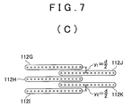
Fig. 7A shows an example of a position deviation of nozzle
arrays in a sub-scanning direction, Fig. 7B shows the amount
of the position deviation above and Fig. 7C shows a method
for measuring the amount of the position deviation in a
sub-scanning direction caused by ink dots performed by the
nozzle arrays having the amount of the position deviation.
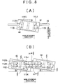
Fig. 8A shows another example of a position deviation
of nozzle arrays in a sub-scanning direction, Fig. 8B shows
the amount of the position deviation above and Fig. 8C shows
a method for measuring the amount of the position deviation
in a sub-scanning direction caused by ink dots performed by
the nozzle arrays having the amount of the position deviation.
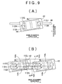
Fig. 9A shows further another example of a position
deviation of nozzle arrays in a sub-scanning direction, Fig.
9B shows the amount of the position deviation above and Fig.
9C shows a method for measuring the amount of the position
deviation in a sub-scanning direction caused by ink dots
performed by the nozzle arrays having the amount of the position
deviation.
Fig. 10 shows an example of a flowchart illustrating
processes of a recording position correction method according
to the present embodiment.
Fig. 11 shows processes of a correction step S110 in
detail.
BEST MODE FOR PRACTICING THE INVENTION
The invention will now be described based on the preferred
embodiments, which do not intend to limit the scope of the
present invention, but exemplify the invention. All of the
features and the combinations thereof described in the
embodiment are not necessarily essential to the invention.
It is anobj ect of a recording position correction method,
an inkjet type recording apparatus and a computer program
therefor according to the present embodiment to make up for
the recording error that occurs due to the imprecise mounting
or looseness of the recording head in order to perform recording
as closely as in a way that a user desires.
Fig. 1 is a side view schematically showing the inner
configuration of an inkjet type recording apparatus. Here,
the ink jet type recording apparatus 10 is an example of a liquid
ejecting apparatus. In addition, a recording head of the inkjet
type recording apparatus 10 is an example of a liquid ejecting
head of the liquid ejecting apparatus. Nozzles arranged on
the recording head are an example of ejecting openings of the
liquid ejecting head. In addition, a medium to be recorded
11 is an example of a target.
However, the inkjet type recording apparatus is not
limited to this embodiment. As another example of the liquid
ejecting apparatus, there is a color filter manufacturing
apparatus for manufacturing a color filter of a liquid crystal
display. In this case, a color material ejecting head of the
color filter manufacturing apparatus is an example of the
liquid ejecting head. Further another example of the liquid
ejecting apparatus is an electrode forming apparatus for
forming electrodes such as an organic EL display, a FED (Field
Emission Display) or the like. In this case, an electrode
material (conduction paste) ejecting head of the electrode
forming apparatus is an example of the liquid ejecting head.
Further another example is a biochip manufacturing apparatus
for manufacturing biochips. In this case, a bio organism
ejecting head of the biochip manufacturing apparatus and a
sample ejecting head as a minute pipette are examples of the
liquid ejecting head. The liquid ejecting apparatus of the
present invention includes other liquid ejecting apparatuses
used for industrial purposes.
The inkjet type recording apparatus 10, as shown in Fig.
1, includes a stack unit 12 for holding a stack of medium to
be recorded 11, a feeding unit 20 for taking one medium to
be recorded 11 out of the stack unit 12 and feeding it in order
to perform recording, a transferring unit 30 for transmitting
force in a feeding direction to the medium to be recorded 11
fed by the feeding unit 20, a recording unit 40 for performing
recording on the medium to be recorded 11 and a discharging
unit 50 for transmitting power to the medium 11 on which recording
is finished in a discharge direction, along the feeding order.
The feeding unit 20 includes a paper feed roller 22 and
a separation pad 24 which are rotated by a motor, not shown,
together with a driving shaft. The paper feed roller 22 is
substantially the shape of a fan, and the driving shaft 26
is provided at the center of an arc that is a part of the fan.
As the paper feed roller 22 is rotated, the paper feed roller
22 repeats contact and separation states with and from the
separation pad 24. In the contact state, the paper feed roller
22 and the separation pad 24 separate the medium to be recorded
11 piled on the stack unit 12 one by one by holding a medium
to be recorded 11 placed on the top of the pile between the
paper feed roller 22 and the separation pad 24, and feed it
to the transferring unit 30. During this feeding process,
the paper feed roller 22 and a hopper that is a part of the
stack unit 12 are separated from each other in order to put
the medium 11 on which recording has not been performed back
to the stack unit 12 for arrangement.
The transferring unit 30 includes a transferring roller
32 that is rotated by a motor 60 and a transfer driven roller
34 that is rotated accompanying the transferring roller 32,
so that it transfers the medium to be recorded 11 fed by the
feeding unit 20 toward a lower part of the recording unit 40
by holding the medium to be recorded 11 at a contact point
between the transferring roller 32 and the transfer driven
roller 34.
The recording unit 40 includes a carriage 42 in which
an ink cartridge is mounted, a recording head 44 provided on
a surface, which faces the medium to be recorded 11, of the
carriage 42 for ejecting ink, an engaging part 46 provided
on the carriage 42, a guide 48 engaged with the engaging part
46 for supporting the carriage 42 to slide freely along at
least either a forward or backward path in a main scanning
direction substantially perpendicular to the feeding direction
and a controlling unit 49 for controlling recording. Here,
a sub-scanning direction is defined as the feeding direction
of the medium to be recorded 11. The controlling unit 49
controls recording by controlling the recording unit 40 and
the transferring unit 30 in accordance with recording timing
data received from an information processing apparatus 300
such as a computer. Further, on the recording head 44, a
plurality of nozzle arrays in each of which a plurality of
nozzles are arranged along a direction in which the medium
to be recorded 11 is transferred (the sub-scanning direction)
are arranged along the main scanning direction of the carriage
42.
The discharging unit 50 includes a discharging roller
52 that is rotated by the motor 60 and a discharge driven roller
54 rotated accompanying the discharging roller 52, so that
it discharges the medium 11 after recording by holding the
medium 11 at a contact point between the discharging roller
52 and the discharge driven roller 54.
Further, the transfer driven roller 34 is provided above
the transferring roller 32 and biased towards the recording
head 44 compared with the transferring roller 32, and the
discharge driven roller 54 is provided above the discharging
roller 52 and biased towards the recording head 44 compared
with the discharging roller 52. Therefore, the medium to be
recorded 11 is bent downwards at a position facing the recording
unit 40.
In the configuration described above, the inkjet type
recording apparatus 10 ejects ink while reciprocating the
recording head 44 along the guide 48. The ink jet type recording
apparatus 10 performs recording for all of the medium to be
recorded 11 by feeding them at each time the recording head
44 performs the scanning operation. Further, the recording
head 44 may perform recording for both forward and backward
paths or may perform for either of them.
Further, the transferring unit 30 and the discharging
unit 50 are supplied with the power transmitted from the motor
60 via a belt 62. The belt 62 is applied with tension by a
tensioner 64. The motor 60, the tensioner 64, the transferring
unit 30 and the discharging unit 50 are arranged in line along
a direction in which the belt 62 flows.
Fig. 2 shows an example of functional blocks of a
controlling unit 49. The controlling unit 49 includes a
recording timing data storing unit 440, a correcting unit 430,
a correction amount storing unit 420, a correction data storing
unit 450 and a correction data outputting unit 400.
The recording timing data storing unit 440 acquires and
stores recording position data to be recorded on the medium
11 from the information processing apparatus 300. In the
present embodiment, the recording timing data storing unit
440 acquires and stores recording timing data that indicates
at which time of scanning the ink should be ejected from the
nozzle as the recording position data. The correction amount
storing unit 420 stores a correction amount for correcting
the recording timing data to correct the recording positions
of ink dots recorded, if there is a position deviation in the
sub-scanning direction of a plurality of nozzle arrays arranged
on the recording head 44. The correction amount of the
recording timing data is calculated based on the position
deviation of a plurality of nozzle arrays in the sub-scanning
direction.
The correcting unit 430 acquires the recording timing
data from the recording timing data storing unit 440 and acquires
the correction amount of the recording timing data from the
correction amount storing unit 420. Further, the correcting
unit 430 corrects the recording timing data by shifting the
recording positions of the ink dots to be recorded in advance
in regard to each nozzle of a plurality of nozzle arrays based
on the correction amount acquired from the correction amount
storing unit 420 and stores it into the correction data storing
unit 450. The correction data outputting unit 400 acquires
the recording timing data corrected from the correction data
storing unit 450, and outputs it to the transferring unit 30
and the recording unit 40. Therefore, the transferring unit
30 and the recording unit 40 records the ink dots on the medium
to be recorded 11 based on the recording timing data corrected.
In addition, as further another modification, a recording
medium 700, in which a computer program for operating the
recording timing data storing unit 440, the correcting unit
430, the correction amount storing unit 420, the correction
data storing unit 450 and the correction data outputting unit
400 is stored, may be installed in the information processing
apparatus 300 and the information processing apparatus 300
may correct the recording timing data based on the computer
program stored in the recording medium 700. The recording
medium 700 may be distributed as utility software. Inaddition,
as another modification, the information processing apparatus
300 may acquire the computer program for operating those units
via a communications line.
In this way, the controlling unit 49 corrects the
recording timing data by shifting the recording positions of
the ink dots to be recorded on the medium 11 in advance based
on the amount of the position deviation in the sub-scanning
direction of a plurality of nozzles. Therefore, in comparison
to a case that correction is performed while the carriage 42
is fitted with the guide 48, in the present embodiment, it
is possible to easily correct the amount of the position
deviation of a plurality of nozzles in the sub-scanning
direction. Further, according to the present embodiment, it
is not necessary that correction is performed while the carriage
42 is fitted with the guide 48, so that the number of parts
of the inkjet type recording apparatus 10 can be reduced.
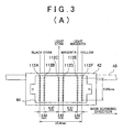
Fig. 3A and 3B are bottom views of the carriage 42 on
which the recording head 44 is provided. Fig. 3A shows a bottom
view of the carriage 42 including a recording head 44 of six
colors and six rows, and Fig. 3B shows a bottom view of the
carriage 42 including a recording head 44 of four colors and
six rows. As shown in Fig. 3A and 3B, the recording head 44
includes a plurality of nozzle arrays, in each of which a
plurality of nozzles for ejecting ink of one color are arranged
in the sub-scanning direction, along the main scanning
direction for each of a plurality of colors.
For example, the recording head 44 in Fig. 3A includes
nozzle arrays 112A to 112F respectively corresponding to six
colors, i.e. BLACK, CYAN, LIGHT CYAN, MAGENTA, LIGHT MAGENTA
and YELLOW. In addition, the recording head 44 in Fig. 3B
includes nozzle arrays 112A to 112F corresponding to four colors,
i.e. BLACK, CYAN, MAGENTA and YELLOW. In addition, each of
the nozzle arrays 112A to 112F includes a plurality of nozzles
(ten nozzles in Figs. 3A and 3B) arranged along the sub-scanning
direction. The intervals of each of the nozzle arrays 112A
to 112F in Fig. 3A are, e.g. 2.82mm, 8.47mm, 2.82mm, 8.47mm
and 2.82mm from the left. In addition, the height of each
row is 9. 95mm. The arrangement intervals of the nozzle arrays
112A to 112F and the height of each row are not limited to
the examples shown in Fig. 3A, and may be other arrangement
interval.
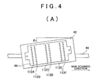
Fig. 4 shows an example of the deviation of a plurality
of nozzle arrays 112 in a sub-scanning direction. Fig. 4A
shows the bottom of the carriage 42. As shown in Fig. 4A,
the carriage 42 might have a tilt of 1 against the longitudinal
direction of the guide 48 due to a bad condition, looseness
or the like of mounting onto the guide 48. Because of the
tilt, each of the nozzle arrays 112A to 112F deviates in the
sub-scanning direction, so that the recording positions of
the ink dots recorded on the medium to be recorded 11 deviate.
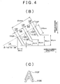
Fig. 4B shows an example of the position deviation in
the sub-scanning direction of a plurality of nozzle arrays
112A to 112F having the recording head 44 shown in Fig. 4A.
In Fig. 4B each of the nozzle arrays 112A to 112F is shown
as solid lines. The carriage 42 shown in Fig. 4B is fitted
with the guide 48 to have an angle or tilt of approximately
0 (zero) degree, 51 minutes and 58 seconds against the
longitudinal direction of the guide 48. In case of the recording
head 44 shown in Fig. 4B, the distance between the nozzle array
112A, the most left one, and the nozzle array 112F, the most
right one, is 25.4mm. The distance between the lowest nozzles
of the nozzle array 112F, the most right one, and the nozzle
array 112A, the most left one, in the sub-scanning direction
is approximately 66µm.
Fig. 4C shows a record result "A" caused by the ink dots
recorded on the medium to be recorded 11 after scanning of
the carriage 42 shown in Fig. 4A and 4B. As shown in Fig.
4B, each nozzle of the nozzle array 112F is positioned to be
higher than each nozzle of the nozzle array 112B in a direction
opposite to the sub-scanning direction by 59µm. Therefore,
as shown in Fig. 4C, the record result "A" formed of the ink
dots recorded by ejection from the nozzle array 112F is
positioned to be higher than the record result "A" formed of
the ink dots recorded by ejection from the nozzle array 112B.
Therefore, the record result "A", which is supposed to be
recorded as one letter, is recorded as two letters in which
the position deviates in the sub-scanning direction.
Particularly, as shown in Fig. 3A and 3B, since the nozzle
arrays 112B and 112F eject ink of colors different from each
other, i.e. cyan and yellow or black and yellow, it is obvious
that the recording position recorded on the medium to be recorded
deviates. Since the resolution of the naked eye is
approximately 20µm, the deviation of the recording position
shown in Fig. C can be recognized to the naked eye.
Fig. 5A and 5B show a correction method of recording
timing data according to the present embodiment. In the present
embodiment, each of the recording positions of the ink dots
recorded with various colors is shifted in advance, and the
recording timing data is shifted and corrected. As shown in
Fig. 4C, the record result "A" formed of the ink dots recorded
by ejection from the nozzle array 112F is positioned to be
higher than the record result "A" formed of the ink dots recorded
by ejection from the nozzle array 112B. Accordingly, as shown
in Fig. 5A, the recording position of "A" to be formed of the
ink dots to be recorded by ejection from the nozzle array 112F
is corrected by shifting the position to be low as much as
2 dots in the sub-scanning direction in advance. In addition,
as shown in Fig. 5B, "A" to be formed of the ink dots to be
recorded by ejection from the nozzle array 112B is not corrected.
In other words, the recording timing data corresponding to
each of the nozzle arrays 112A to 112F is corrected in a direction
opposite to the position deviation of the nozzle arrays 112A
to 112F as much as each of the position deviations of the nozzle
arrays 112A to 112F in the sub-scanning direction caused by
the tilt of the carriage 42.
The amount of the position deviation of each of the nozzle
arrays 112A to 112F in the sub-scanning direction shown in
Fig. 4B is measured in the factory at the time of the shipment
of the ink jet type recording apparatus. The correction amount
of the recording timing data for correcting the recording
position is calculated based on the amount of the measured
deviation, and stored into the correction amount storing unit
420 inadvance. The recording position base don the correction
amount of the recording timing data can be shifted per one
dot. The value of one dot is 1/720 inch, 1/1440 inch or the
like. However, the value of one dot may be adjusted according
to there solution of the inkjet type recording apparatus. Since
1/720 inch is approximately 35µm and the resolution of the
naked eye is about 20µm to 30µm, the recording position can
be corrected to the extent that it cannot be recognized to
the naked eye by shifting the recording position by 1/720 inch.
Further, since 1/1440 inch is approximately 17.5µm, the
recording position can be corrected to even further extent
that it cannot be recognized to the naked eye compared with
1/720 inch.
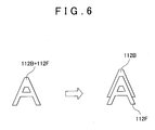
Fig. 6 shows recording results of combining each color
before and after a correction. In case of using the recording
head 44 of 6 colors and 6 rows shown in Fig. 3A, if the recording
head 44 is not tilted to the guide 48, in the recording result
of combining each color before the correction shown as the
left one in Fig. 6, "A" recorded by the ink ejected from the
nozzle array 112B and "A" recorded by the ink ejected from
the nozzle array 112F are positioned uniformly in the
sub-scanning direction. On the other hand, in the recording
result of combining each color after the correction shown as
the right one in Fig. 6, "A" recorded by the ink ejected from
the nozzle array 112F is corrected to be shifted in the
sub-scanning direction as much as 2 dots downwardly than "A"
recorded by the ink ejected from the nozzle array 112B as shown
in Fig. 5A and 5B. Therefore, if recording is performed on
the medium to be recorded 11 in the corrected state above by
using the carriage 42 normally fitted with the guide 48, two
letters of "A" will be recorded while one is shifted against
the other in the sub-scanning direction.
However, if recording is performed on the medium to be
recorded 11 in the corrected state above by using the carriage
42 fitted with the guide 48 while it is tilted as shown in
Fig. 4A and 4B, since the recording position is shifted in
advance as much as the deviation amount of the nozzle 112 in
the sub-scanning direction, in contrast that two letters are
recorded on the medium to be recorded 11 while one is shifted
against the other in the sub-scanning direction before the
correction, one letter of "A", which is supposed to be shown
on the medium to be recorded 11, is recorded. In the examples
in Fig. 4 to Fig. 6, since "A" that is formed of the ink dots
to be recorded by ejection from the nozzle array 112F is corrected
in advance to be shifted in the sub-scanning direction by 2
dots downwardly than "A" that is formed of the ink dots to
be recorded by ejection from the nozzle array 112F, "A" formed
of the ink dots ejected and recorded from the nozzle array
112F and "A" formed of the ink dots ejected and recorded from
the nozzle array 112F are recorded to substantially match with
each other.
In this way, the inkjet type recording apparatus
according to the present embodiment shifts the recording
positions of ink dots to be recorded on the medium 11 based
on the amount of the position deviation of a plurality of nozzle
arrays 112A to 112F in the sub-scanning direction. Therefore,
even if the carriage 42 is fitted with the guide 48 while it
is tilted, recording can be performed on the medium to be recorded
11 in the shape supposed to be recorded without adjusting the
carriage 42 mechanically.
Fig. 7 to 9 show an example of a method for measure the
amount of the position deviationof a plurality of nozzle arrays
112A to 112F in the sub-scanning direction according to the
present embodiment. Fig. 7A shows a state that the carriage
42 is fitted with the guide 48 normally. In the present
embodiment, to measure the amount of the position deviation
of the nozzle arrays 112A to 112F in the sub-scanning direction,
the ink dots are recorded on the medium to be recorded 11 by
ejecting ink from at least one nozzle of each of at least two
nozzle arrays most distanced from each other in the main scanning
direction among a plurality of nozzle arrays 112A to 112F.
For example, at least one of a pair of nozzles, i.e. a first
nozzle 112G from the top of the most left nozzle array 112A
and a second nozzle 112J from the top of the most right nozzle
array 112F or a pair of nozzles, i.e. a lowest nozzle 112I
of the most left nozzle array 112A and a fourth nozzle 112K
of the most right nozzle array 112F is used. The reason why
a pair of nozzles most distanced from each other in the main
scanning direction are used is because the amount of deviation
of the nozzle 112 in the sub-scanning direction is largest
as shown in Fig. 4B. Therefore, the amount of deviation can
be exactly measured.
The amounts of deviation of other nozzle arrays except
the two nozzle arrays distanced from each other in the main
scanning direction can be obtained by dividing the amount of
deviation of the two nozzle arrays distanced from each other
in the main scanning direction inproportion to the arrangement
interval of each nozzle array in regard to the recording head
44 shown in Fig. 3A.
In case of Fig. 7A, the first, third and fifth nozzles
112G, 112H and 112I from the top of the most left nozzle array
112A surrounded by a broken line and the second and fourth
nozzles 112J and 112K from the top of the most right nozzle
array 112F surrounded by a broken line are used. Since the
distance to be measured becomes large by making the numbers
1, 3 and 5 of the used nozzles of the most left nozzle array
112A and the numbers 2 and 4 of the used nozzles of the most
right nozzle array 112F different, the amount of deviation
of the nozzle 112 in the sub-scanning direction can be easily
measured.
In addition, as shown in Fig. 7A, each of the nozzles
112G to 112K is arranged on the recording head 44 in order
that if the interval between the nozzles 112G and 112H in the
sub-scanning direction is defined as d, the interval between
the nozzles 112G and 112J in the sub-scanning direction becomes
d/2, the interval between the nozzles 112H and 112I in the
sub-scanning direction becomes d and the interval between the
nozzles 112I and 112K in the sub-scanning direction becomes
d/2.
Fig. 7B shows the loci drawn by each of the nozzles 112G
to 112K when the carriage 42 moves to the right, i.e. through
the forward path in the main scanning direction along the guide
48, and Fig. 7C shows ink dots ejected and recorded on the
medium to be recorded 11 when the carriage 42 performs a scanning
operation as shown in Fig. 7B while ejecting ink from the nozzles
112G to 112K. Since the carriage 42 is fitted with the guide
48 without a tilt, as shown in Fig. 7B, the interval y1 between
the loci drawn by the nozzles 112G and 112J in the sub-scanning
direction is d/2 and the interval y2 between the loci drawn
by the nozzles 112I and 112K in the sub-scanning direction
is d/2.
Therefore, as shown in Fig. 7C, the interval y1 in the
sub-scanning direction between a line formed by the ink dots
ejected from the nozzle 112G and recorded on the medium to
be recorded 11 and a line formed by the ink dots ejected from
the nozzle 112J and recorded on the medium to be recorded 11
isd/2, and the interval y2 in the sub-scanning direction between
a line formed by the ink dots ejected from the nozzle 112I
and recorded on the medium to be recorded 11 and a line formed
by the ink dots ejected from the nozzle 112K and recorded on
the medium to be recorded 11 is d/2. In other words, if the
carriage 42 is fitted with the guide 48 normally, the intervals
y1 and y2 in the sub-scanning direction between lines formed
by the ink dots recorded on the medium to be recorded 11 from
each of the nozzles 112G to 112K become d/2. Accordingly,
if the values resulting from measuring the intervals y1 and
y2 are not equal to d/2, it can be judges that the carriage
42 is fitted with the guide 48 while it is tilted.
Fig. 8A shows a carriage 42 fitted with the guide 48
while the left end of the carriage 42 is tilted in the sub-scanning
direction. In an example shown in Fig. 8A, the carriage 42
has a tilt of 1 against the longitudinal direction of the
guide 48. Fig. 8B shows the loci drawn by each of the nozzles
112G to 112K when the carriage 42 shown in Fig. 8A moves to
the right, i.e. through the forward path in the main scanning
direction along the guide 48, and Fig. 8C shows ink dots ejected
and recorded on the medium to be recorded 11 when the carriage
42 performs a scanning operation as shown in Fig. 8B while
ejecting ink from the nozzles 112G to 112K. As shown in Fig.
8B, the interval y1 between the loci drawn by the nozzles 112G
and 112J in the sub-scanning direction is larger than d/2 and
the interval y2 between the loci drawn by the nozzles 112I
and 112K in the sub-scanning direction is smaller than d/2.
Therefore, as shown in Fig. 8C, the interval y1 in the
sub-scanning direction between a line formed by the ink dots
ejected from the nozzle 112G and recorded on the medium to
be recorded 11 and a line formed by the ink dots ejected from
the nozzle 112J and recorded on the medium to be recorded 11
is larger than d/2. And, the interval y2 in the sub-scanning
direction between a line formed by the ink dots ejected from
the nozzle 112I and recorded on the medium to be recorded 11
and a line formed by the ink dots ejected from the nozzle 112K
and recorded on the medium to be recorded 11 is smaller than
d/2. In addition, since the amount of the position deviation
of the nozzle array in the direction in which the carriage
42 is tilted to the guide 48 and in the sub-scanning direction
can be obtained from the intervals y1 and y2, the correction
amount of the recording timing in regard to each nozzle of
a plurality of nozzle arrays can be calculated based on the
obtained amount of the deviation.
Fig. 9A shows a carriage 42 fitted with the guide 48
while the right end of the carriage 42 is tilted in the
sub-scanning direction. In an example shown in Fig. 9A, the
carriage 42 has a tilt of 2 against the longitudinal direction
of the guide 48. Fig. 9B shows the loci drawn by each of the
nozzles 112G to 112K when the carriage 42 shown in Fig. 9A
moves to the right, i.e. through the forward path in the main
scanning direction along the guide 48, and Fig. 9C shows ink
dots ejected and recorded on the medium to be recorded 11 when
the carriage 42 performs a scanning operation as shown in Fig.
9B while ejecting ink from the nozzles 112G to 112K. As shown
in Fig. 9B, the interval y1 between the loci drawn by the nozzles
112G and 112J in the sub-scanning direction is smaller than
d/2 and the interval y2 between the loci drawn by the nozzles
112I and 112K in the sub-scanning direction is larger than
d/2.
Therefore, as shown in Fig. 9C, the interval y1 in the
sub-scanning direction between a line formed by the ink dots
ejected from the nozzle 112G and recorded on the medium to
be recorded 11 and a line formed by the ink dots ejected from
the nozzle 112J and recorded on the medium to be recorded 11
is smaller than d/2. And, the interval y2 in the sub-scanning
direction between a line formed by the ink dots ejected from
the nozzle 112I and recorded on the medium to be recorded 11
and a line formed by the ink dots ejected from the nozzle 112K
and recorded on the medium to be recorded 11 is larger than
d/2. Therefore, if the values resulting from measuring the
intervals y1 and y2 are not equal to d/2, it can be judges
that the carriage 42 is fitted with the guide 48 while it is
tilted.
In addition, the interval y1 is larger than the interval
y2 in case of Fig. 8, and the interval y1 is small than the
interval y2 in case of Fig. 9. Therefore, if the directions
in which the carriage 42 is tilted to the guide 48 are different
as shown in Fig. 8 and 9, the values of the intervals y1 and
y2 are different. Accordingly, the direction in which the
carriage 42 is tilted to the guide 48 can be known from the
intervals y1 and y2. Further, since the amount of deviation
of nozzles in the sub-scanning direction can be obtained from
the intervals y1 and y2, the correction amount of the recording
timing in regard to each nozzle of a plurality of nozzle arrays
can be calculated based on the obtained amount of the deviation.
Moreover, the intervals y1 and y2 are changed
corresponding to the tilt 1 or 2 of the carriage 42 to the
guide 48. However, since the intervals y1 and y2 are not d/2
in case the carriage 42 is fitted with the guide 48 while it
is tilted, it can be judged whether the carriage 42 is tilted
to the guide 48 by measuring the intervals y1 and y2.
In addition, alternatively, the amount of the position
deviation of nozzles in the sub-scanning direction may be
measured based on recoding results on the medium to be recorded
11 performed by the ink ejected from the nozzles of other nozzle
arrays except the nozzles 112G and 112J or 112I and 112K of
the two nozzle arrays most distanced from each other. For
example, the amount of the position deviation of nozzles in
the sub-scanning direction may be measured based on recoding
results on the medium to be recorded 11 performed by the ink
dots ejected and recorded from the nozzles of one of the nozzle
arrays 112B to 112E existing between the two nozzle arrays
most distanced from each other.
In calculating the correction amount of the recording
timing by obtaining the amount of the position deviation in
the sub-scanning direction of the nozzle arrays 112B to 112E
existingbetween the two nozzle arrays 112A and 112F by dividing
the amount of the position deviation in the sub-scanning
direction of the two nozzle arrays 112A and 112F most distanced
from each other in the main scanning direction in proportion
to the arrangement relation of each nozzle array in regard
to the recording head 44, it might be difficult to judge the
correction amount of the recording timing of the nozzle arrays
112B to 112E even by the amount of the position deviation in
the sub-scanning direction of the two nozzle arrays 112A and
112F.
For example, if the amount of deviation of the two nozzle
arrays 112A and 112F in the sub-scanning direction is 2.6 dots,
it is determined as a shift of 3 dots. At this time, if the
value obtained by dividing in proportion to the deviation amount
of the nozzle array 112D is 1.5, correct ion might not be performed
to the extent that the position deviation of the ink dots recorded
is not recognized to the naked eye by shifting the nozzle array
112D by 2 dots. Accordingly, by further measuring the amount
of the position deviation in the sub-scanning direction of
the nozzle arrays 112B to 112E between the two nozzle arrays
112A and 112F as well, the correction amount of the recording
timing corresponding to the nozzle arrays 112B to 112E can
be calculated accurately. In the example above, if the amount
of deviation in the sub-scanning direction of the two nozzle
arrays 112A and 112F most distanced from each other is 2.6
dots, by measuring the amount of the position deviation of
the nozzle array 112D, the recording position of the ink dots
the nozzle array 112D is shifted by 1 dot, so that correction
is performed to the extent that the position deviation of the
ink dots recorded by the nozzle array 112D is not recognized
to the naked eye.
In addition, if the carriage 42 is fitted with the guide
48 loosely, the carriage 42 rattles during moving. Therefore,
the tilt of the carriage 42 to the guide 48 is changed both
when the carriage 42 moves to the right, i.e. along the forward
path in the main scanning direction and when the carriage 42
moves to the left, i.e. along the backward path in the main
scanning direction. For example, when the carriage 42 moves
along the forward path in the main scanning direction, the
right end of the carriage 42 is tilted in the sub-scanning
direction as shown in Fig. 8, and when the carriage 42 moves
along the backward path in the main scanning direction, the
left end of the carriage 42 is tilted in the sub-scanning
direction as shown in Fig. 9. If the ink is ejected from the
recording head 44 while the carriage 42 with looseness performs
scanning operations in both directions along the forward and
backward paths in the main scanning direction, the deviation
of the recording position might be considerable.
Accordingly, the recording position may be corrected
by obtaining an intermediate value between the amount of the
position deviation of the recording position in the
sub-scanning direction in case the recording head 44 performs
scanning along the forward path in the main scanning direction
and the amount of the position deviation of the recording
position in the sub-scanning direction in case the recording
head 44 performs scanning along the backward path in the main
scanning direction and shifting the recording timing in advance
based on the intermediate value. Therefore, it is possible
to correct the position deviation of the recording position
even when recording is performed in both directions, i.e. the
forward and backward paths in the main scanning direction.
In addition, alternatively, the amount of the position
deviation of the recording position in the sub-scanning
direction in case the recording head 44 performs scanning along
the forward path in the main scanning direction and the amount
of the position deviation of the recording position in the
sub-scanning direction in case the recording head 44 performs
scanning along the backward path in the main scanning direction
may be measured separately, so that the recording position
in regard to the forward path in the main scanning direction
can be shifted in advance based on the amount of the position
deviation of the recording position in the sub-scanning
direction in case the recording head 44 performs scanning along
the forward path in the main scanning direction, while the
recording position in regard to the backward path in the main
scanning direction can be shifted in advance based on the amount
of the position deviation of the recording position in the
sub-scanning direction in case the recording head 44 performs
scanning along the backward path in the main scanning direction.
In this case, it is possible to correct the position deviation
of the recording position of the ink dots recorded in each
directionof the forward and backward paths in the main scanning
direction.
In addition, alternatively, the ink may be ejected from
nozzles of two nozzle arrays ejecting two colors respectively
as priority is given to a color whose density is highest among
a plurality of nozzle arrays, so that the recording position
on the medium to be recorded in regard to each of the plurality
of nozzles can be shifted in advance based on the amount of
the position deviation of the recording position of the ink
dots ejected and recorded from the nozzles. For example, the
nozzle array 112B ejecting cyan whose density is high or the
nozzle array 112D ejecting magenta whose density is high and
the nozzle 112G ejecting black may be used. By using ink whose
density is high, the visibility of recording results on the
medium to be recorded 11 is increased, and thus it is possible
to measure the amount of the position deviation of the recording
position of the ink dots easily.
In this way, in the present embodiment, the ink dots
are recorded on the medium to be recorded 11 by ejecting ink
from a plurality of nozzle arrays 112A to 112F in order that
the colors of ink are different respectively, and the amount
of the position deviation of the recording position in the
sub-scanning direction is measured for each color of the ink
dots. Therefore, by using the measured amount of deviation
of the nozzle 112, as shown in Fig. 5 and Fig. 6, the recording
position of different color is shifted respectively in advance,
so that correction can be performed. Therefore, even if the
carriage 42 is fitted with the guide 48 while it is tilted,
recording can be performed on the medium to be recorded 11
in the shape supposed to be recorded without adjusting the
carriage 42 mechanically.
Fig. 10 is an example of the flowchart showing processes
of a recording position correction method according to the
present embodiment. The recording position correction method
according to the present embodiment includes a setting step
S106 of setting the correction amount of the recording timing
to the inkjet type recording apparatus 10 in the factory or
the like and a correction step S110 of correcting the recording
timing data during the use of the inkjet type recording apparatus
10.
In the setting step S106, as described in Figs. 7 to
9, the ink dots are recorded on the medium to be recorded 11
by ejecting ink nozzles of predetermined nozzle arrays 112A
to 112F based on the test data (S100), and the amount of the
position deviation in the sub-scanning direction of the ink
dots recorded on the medium to be recorded 11 is measured and
the correction amount of the recording timing is calculated
(S102). Next, the calculated correction amount is stored into
the correction amount storing unit 420 of the controlling unit
49 (S104). Next, the recording timing data is corrected based
on the correction amount based on the correction amount storing
unit 420 of the inkjet type recording apparatus 10 and the
ink dots desired are recorded on the medium to be recorded
11 (S110).
Fig. 11 shows the correction step S110 indetail. First,
the recording timing data supposed to be recorded on the medium
to be recorded 11 is generated (S112). Next, the data of the
color of the generated recording timing data is separated for
each color that the recording head 44 has (S114). Next, as
described in Fig. 5 and Fig. 6, the recording timing data is
corrected based on the correction amount of nozzles of nozzle
arrays corresponding to each color (S116). Next, whether the
process has been completed for the data of all colors is judged
(S118). If the process has not yet been completed for the
data of all colors (S118, No), the recording timing data of
the next color is corrected (S116).
If the process has been completed for the data of all
colors (S118, Yes), whether the process has been completed
for the recording timing data of one scanning portion of the
carriage 42 is judged (S120). If the process has not yet been
completed for the recording timing data of one scanning portion
(S120, No), the data of the color of the next pixel is separated
(S114). If the process has been completed for the recording
timing data of one scanningportion (S120, Yes), the correction
data is outputted to the transferring unit 30 and the recording
unit 40, and the ink dots are recorded on the medium to be
recorded 11 based on the corrected recording timing data (S122).
Next, whether the recording has been completed on the medium
to be recorded 11 is judged (S124), if the recording has not
yet been completed (S124, No), the data of the next color is
separated (S114). If the recording has been completed (S124,
Yes), process of, e.g. cleaning the recording head 44 is
performed after recording is completed (S126). Therefore,
by obtaining the correction amount of the recording timing
in regard to initial setting before shipment, the position
deviation of the recording position of the ink dots in the
sub-scanning direction can be corrected during the use of a
user. The process of correcting the recording timing shown
in Fig. 11 may be performed by the inkjet type recording apparatus
10.
In addition, the process of correcting the recording
timing shown in Fig. 11 may be performed by a user with the
information processing apparatus 300. If a user corrects the
recording position by using the information processing
apparatus 300, the information processing apparatus 300
acquires the correction amount stored in the inkjet type
recording apparatus 10 and corrects the recording timing data
based on the computer program stored in the recording medium
700 or the like, and outputs the corrected recording timing
data to the inkjet type recording apparatus 10 in order to
perform recording on the medium to be recorded 11. Therefore,
a user can correct the recording position by using the
information processing apparatus 300 if the looseness of the
carriage 42 becomes large during the use of the inkjet type
recording apparatus 10.
Although the present invention has been described by
way of exemplary embodiments, it should be understood that
those skilled in the art might make many changes and
substitutions without departing from the spirit and the scope
of the present invention, which is defined only by the appended
claims.
As obvious from the description above, according to the
present invention, it is possible to shift and correct each
of the recording positions in advance by correcting the
recording timing corresponding to the amount of the position
deviation in the sub-scanning direction of nozzles of each
of the nozzle arrays 112A to 112F. Thus, even if the carriage
42 is fitted with the guide 48 while it is tilted, recording
can be performed on the medium to be recorded 11 in the shape
supposed to be recorded without adjusting the carriage 42
mechanically.