EP1533071A2 - Method for repairing gas turbine rotor blades - Google Patents
Method for repairing gas turbine rotor blades Download PDFInfo
- Publication number
- EP1533071A2 EP1533071A2 EP04256954A EP04256954A EP1533071A2 EP 1533071 A2 EP1533071 A2 EP 1533071A2 EP 04256954 A EP04256954 A EP 04256954A EP 04256954 A EP04256954 A EP 04256954A EP 1533071 A2 EP1533071 A2 EP 1533071A2
- Authority
- EP
- European Patent Office
- Prior art keywords
- blade
- sidewall
- rotor blade
- replacement
- blade portion
- Prior art date
- Legal status (The legal status is an assumption and is not a legal conclusion. Google has not performed a legal analysis and makes no representation as to the accuracy of the status listed.)
- Withdrawn
Links
Images



Classifications
-
- B—PERFORMING OPERATIONS; TRANSPORTING
- B23—MACHINE TOOLS; METAL-WORKING NOT OTHERWISE PROVIDED FOR
- B23P—METAL-WORKING NOT OTHERWISE PROVIDED FOR; COMBINED OPERATIONS; UNIVERSAL MACHINE TOOLS
- B23P6/00—Restoring or reconditioning objects
- B23P6/002—Repairing turbine components, e.g. moving or stationary blades, rotors
- B23P6/005—Repairing turbine components, e.g. moving or stationary blades, rotors using only replacement pieces of a particular form
-
- F—MECHANICAL ENGINEERING; LIGHTING; HEATING; WEAPONS; BLASTING
- F01—MACHINES OR ENGINES IN GENERAL; ENGINE PLANTS IN GENERAL; STEAM ENGINES
- F01D—NON-POSITIVE DISPLACEMENT MACHINES OR ENGINES, e.g. STEAM TURBINES
- F01D5/00—Blades; Blade-carrying members; Heating, heat-insulating, cooling or antivibration means on the blades or the members
- F01D5/005—Repairing methods or devices
-
- B—PERFORMING OPERATIONS; TRANSPORTING
- B23—MACHINE TOOLS; METAL-WORKING NOT OTHERWISE PROVIDED FOR
- B23K—SOLDERING OR UNSOLDERING; WELDING; CLADDING OR PLATING BY SOLDERING OR WELDING; CUTTING BY APPLYING HEAT LOCALLY, e.g. FLAME CUTTING; WORKING BY LASER BEAM
- B23K2101/00—Articles made by soldering, welding or cutting
- B23K2101/001—Turbines
-
- Y—GENERAL TAGGING OF NEW TECHNOLOGICAL DEVELOPMENTS; GENERAL TAGGING OF CROSS-SECTIONAL TECHNOLOGIES SPANNING OVER SEVERAL SECTIONS OF THE IPC; TECHNICAL SUBJECTS COVERED BY FORMER USPC CROSS-REFERENCE ART COLLECTIONS [XRACs] AND DIGESTS
- Y02—TECHNOLOGIES OR APPLICATIONS FOR MITIGATION OR ADAPTATION AGAINST CLIMATE CHANGE
- Y02T—CLIMATE CHANGE MITIGATION TECHNOLOGIES RELATED TO TRANSPORTATION
- Y02T50/00—Aeronautics or air transport
- Y02T50/60—Efficient propulsion technologies, e.g. for aircraft
-
- Y—GENERAL TAGGING OF NEW TECHNOLOGICAL DEVELOPMENTS; GENERAL TAGGING OF CROSS-SECTIONAL TECHNOLOGIES SPANNING OVER SEVERAL SECTIONS OF THE IPC; TECHNICAL SUBJECTS COVERED BY FORMER USPC CROSS-REFERENCE ART COLLECTIONS [XRACs] AND DIGESTS
- Y10—TECHNICAL SUBJECTS COVERED BY FORMER USPC
- Y10T—TECHNICAL SUBJECTS COVERED BY FORMER US CLASSIFICATION
- Y10T29/00—Metal working
- Y10T29/49—Method of mechanical manufacture
- Y10T29/49316—Impeller making
- Y10T29/49318—Repairing or disassembling
-
- Y—GENERAL TAGGING OF NEW TECHNOLOGICAL DEVELOPMENTS; GENERAL TAGGING OF CROSS-SECTIONAL TECHNOLOGIES SPANNING OVER SEVERAL SECTIONS OF THE IPC; TECHNICAL SUBJECTS COVERED BY FORMER USPC CROSS-REFERENCE ART COLLECTIONS [XRACs] AND DIGESTS
- Y10—TECHNICAL SUBJECTS COVERED BY FORMER USPC
- Y10T—TECHNICAL SUBJECTS COVERED BY FORMER US CLASSIFICATION
- Y10T29/00—Metal working
- Y10T29/49—Method of mechanical manufacture
- Y10T29/49718—Repairing
- Y10T29/49721—Repairing with disassembling
- Y10T29/49723—Repairing with disassembling including reconditioning of part
- Y10T29/49725—Repairing with disassembling including reconditioning of part by shaping
- Y10T29/49726—Removing material
-
- Y—GENERAL TAGGING OF NEW TECHNOLOGICAL DEVELOPMENTS; GENERAL TAGGING OF CROSS-SECTIONAL TECHNOLOGIES SPANNING OVER SEVERAL SECTIONS OF THE IPC; TECHNICAL SUBJECTS COVERED BY FORMER USPC CROSS-REFERENCE ART COLLECTIONS [XRACs] AND DIGESTS
- Y10—TECHNICAL SUBJECTS COVERED BY FORMER USPC
- Y10T—TECHNICAL SUBJECTS COVERED BY FORMER US CLASSIFICATION
- Y10T29/00—Metal working
- Y10T29/49—Method of mechanical manufacture
- Y10T29/49718—Repairing
- Y10T29/49732—Repairing by attaching repair preform, e.g., remaking, restoring, or patching
Definitions
- This application relates generally to gas turbine engines and, more particularly, to methods for repairing gas turbine engine rotor blades.
- At least some known gas turbine engines include a compressor for compressing air which is mixed with a fuel and channeled to a combustor wherein the mixture is ignited within a combustion chamber for generating hot combustion gases.
- the hot combustion gases are channeled downstream to a turbine, which extracts energy from the combustion gases for powering the compressor, as well as producing useful work to propel an aircraft in flight or to power a load, such as an electrical generator.
- Known compressors include a rotor assembly that includes at least one row of circumferentially spaced rotor blades.
- Each rotor blade includes an airfoil that includes a pressure side, and a suction side connected together at leading and trailing edges.
- Each airfoil extends radially outward from a rotor blade platform.
- Each rotor blade also includes a dovetail that extends radially inward from a shank coupled to the platform. The dovetail is used to mount the rotor blade within the rotor assembly to a rotor disk or spool.
- the rotor blade is formed integrally with the rotor disk or spool.
- leading and trailing edges of the blade and/or a tip of the compressor blade may deteriorate or become damaged due to any of a number of distress modes, including, but not limited to, foreign object damage (FOD), tip rubbing, oxidation, thermal fatigue cracking, or erosion caused by abrasives and corrosives in the flowing gas stream.
- FOD foreign object damage
- the blades are periodically inspected for damage, and a determination of an amount of damage and/or deterioration is made. If the blades have lost a substantial quantity of material they are replaced. If the blades have only lost a small quantity material, they may be returned to service without repair. Alternatively, if the blades have lost an intermediate quantity of material, the blades may be repaired.
- At least one known method of repairing a turbine compressor blade includes mechanically removing, such as by grinding, a worn and/or damaged tip area and then adding a material deposit to the tip to form the tip to a desired dimension.
- the material deposit may be formed by several processes including welding and/or thermal spraying.
- special tooling is also used to achieve the precise dimensional relations between the original portion of the compressor blade and the added portion of the compressor blade.
- replacing a portion of a compressor blade may be a time-consuming and expensive process.
- more complex airfoil shapes, for example three-dimensional aerodynamic configurations may increase the difficulty of welding and blending the repaired blade, thus resulting in increased repair costs.
- a method for replacing a portion of a gas turbine engine rotor blade, the rotor blade having a contour defined by a blade first sidewall and a blade second sidewall includes cutting through the rotor blade such that a cut line extends from a leading edge of the blade to a trailing edge of the blade, and between the first sidewall and the second sidewall, removing the portion of the rotor blade that is radially outward of the cut line, and coupling a replacement blade portion to remaining blade portion such that the newly formed rotor blade is formed with a pre-determined aerodynamic contour.
- a method for replacing a portion of a gas turbine engine rotor blade including a leading edge, a trailing edge, a first sidewall, and a second sidewall, and having a contour defined by the first sidewall and the second sidewall includes uncoupling the rotor blade from the gas turbine engine, cutting through the rotor blade such that a cut line extends from the leading edge to the trailing edge, and between the first sidewall and the second sidewall, removing the portion of the rotor blade radially outward of the cut line, coupling a replacement blade portion to the remaining blade portion, and contouring the replacement blade portion such that the newly formed rotor blade is formed with a pre-determined aerodynamic contour.
- a method for replacing a portion of a gas turbine engine rotor blade including a leading edge, a trailing edge, a first sidewall, and a second sidewall, and having a contour defined by the first sidewall and the second sidewall is provided.
- the method includes uncoupling a compressor rotor blade from the gas turbine engine, cutting through a portion of the rotor blade such that a cut line extends from the leading edge to the trailing edge, and between the first sidewall and the second sidewall, removing a portion of the rotor blade radially outward of the cut line, welding a replacement blade portion to the portion of the compressor rotor blade remaining, and contouring the replacement blade portion such that the newly formed compressor rotor blade has a contour that substantially mirrors that of the original compressor rotor blade contour.
- FIG. 1 is a schematic illustration of a gas turbine engine 10 including a fan assembly 12, a high pressure compressor 14, and a combustor 16.
- Engine 10 also includes a high pressure turbine 18, a low pressure turbine 20, and a booster 22.
- Fan assembly 12 includes an array of fan blades 24 extending radially outward from a rotor disc 26.
- Engine 10 has an intake side 28 and an exhaust side 30.
- the gas turbine engine is a GE90 available from General Electric Company, Cincinnati, Ohio.
- engine 10 includes a low pressure compressor.
- Fan assembly 12 and turbine 20 are coupled by a first rotor shaft 31, and compressor 14 and turbine 18 are coupled by a second rotor shaft 32.
- Airflow (not shown in Figure 1) from combustor 16 drives turbines 18 and 20, and turbine 20 drives fan assembly 12 by way of shaft 31.
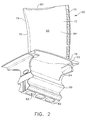
- FIG 2 is an enlarged perspective view of an exemplary rotor blade 50 that may be used with gas turbine engine 10 (shown in Figure 1).
- Figure 3 is an enlarged perspective view of a damaged rotor blade 50 that may be removed from gas turbine engine 10 (shown in Figure 1).
- Figure 4 is an enlarged perspective view of blade 50 repaired using the methods described herein. Although only a single rotor blade 50 is shown, it should be realized that turbine engine 10 includes a plurality of rotor blades 50.
- Each rotor blade 50 includes an airfoil 60, a platform 62, a shank 64, and a dovetail 66.
- Each airfoil 60 includes a first sidewall 70 and a second sidewall 72.
- First sidewall 70 is convex and defines a suction side of airfoil 70
- second sidewall 72 is concave and defines a pressure side of airfoil 60.
- Sidewalls 70 and 72 are joined at a leading edge 74 and at an axially-spaced trailing edge 76 of airfoil 60. More specifically, airfoil trailing edge 76 is spaced chord-wise and downstream from airfoil leading edge 74.
- First and second sidewalls 70 and 72 extend longitudinally or radially outward in span from a blade root 78 positioned adjacent platform 62, to an airfoil tip 80.
- Airfoil tip 80 defines a radially outer boundary of an internal cooling chamber 82.
- Cooling chamber 82 is bounded within airfoil 60 between sidewalls 70 and 72, and extends through platform 62 and through shank 64 and into dovetail 66. More specifically, airfoil 60 includes an inner surface 83 and an outer surface 84, and cooling chamber 82 is defined by airfoil inner surface 83.
- Platform 62 extends between airfoil 60 and shank 64 such that each airfoil 60 extends radially outward from each respective platform 62.
- Shank 64 extends radially inwardly from platform 62 to dovetail 66.
- Dovetail 66 extends radially inwardly from shank 64 and facilitates securing rotor blade 50 to rotor disk 26.
- Deteriorated and/or damaged regions 86 of rotor blade 50 may be removed and replaced using the methods described herein. More specifically, deteriorated and/or damaged regions 86 of airfoil 60 including leading edge 74, trailing edge 76, and airfoil tip 80, may be removed and replaced using the methods described herein. If an engine, such as engine 10, indicates that rotor blade 50 includes at least one damaged and/or deteriorated portion 86 of rotor blade 50 is removed from engine 10 and repaired using the methods described herein.
- the exemplary repair method includes machining, or cutting away, an upper damaged portion 90 of airfoil 60.
- damaged portion 90 includes a radial height 92 measured from an upper surface 94 of damaged portion 90 to a lower surface 96 of damaged portion 90.
- blade 50 is either machined or cut such that damaged portion 90 is separated from the preserved, or remaining, portion 98 of airfoil 60.
- a cut illustrated with line 110 is made through airfoil 60, such that cut 110 extends from leading edge 74 to trailing edge 76, and from first sidewall 70 to second sidewall 72.
- damaged portion 90 is defined as extending radially outward of cut line 110 to airfoil tip 80. Any portion of airfoil 60 extending radially outward of cut line 110 is then defined as damaged portion 90, and is removed and replaced with an undamaged upper portion (not shown) using the methods described herein.
- FIG. 4 is an enlarged perspective view of rotor blade 50 repaired using the methods described herein.
- a replacement 120 is coupled to portion 98.
- Replacement blade portion 120 has a height 122 substantially equivalent to height 92 of removed damaged portion 90. More specifically, in the exemplary embodiment, portion 120 is coupled to preserved portion 98. More specifically, portion 120 is resistance welded to preserved portion 98 such that a material 126 used to join portion 120 and preserved portion 98 comes from preserved portion 98 and portion 120.
- undamaged upper portion 120 has a predetermined blade contour, defined by opposite sidewalls 70 and 72, that is substantially equivalent to a contour of damaged upper portion 90, such that when undamaged upper portion 120 is coupled to preserved lower portion 98, repaired airfoil 60 has a substantially equivalent contour as its original contour.
- undamaged upper portion 120 is coupled to preserved lower portion 98, such that repaired airfoil 60 has a predetermined contour that is improved from the original contour. More specifically, undamaged portion 120 has a predetermined contour that provides an improved aerodynamic shape such that the repaired blade has an improved aerodynamic performance compared to the original blade.
- welding material 126 is formed along line 110 from leading edge 74 to trailing edge 76, and from first 70 to second sidewall 72 along line 110.
- welding material 126 includes at least one of a nickel alloy and a titanium alloy.
- Welding material 126 is then machined to obtain a desired finished dimension. Machining welding material 126 includes rough-blending, and final-blending the welded replacement, such that repaired compressor rotor blade 150 has a contour that substantially mirrors the contour of damaged compressor rotor blade 50.
- a joint 152 between replacement tip 120 and preserved portion 98 may be configured and placed where it can be a simple geometry, and then welded using a high yield automated process. Additionally, undamaged portion 120 may be fabricated from a material similar to damaged portion 90 thereby more closely matching the original material, i.e. forged vs. cast.
- the methods described herein can be adapted to weld common blade alloys such as, but not limited to, a nickel based alloy, a titanium based alloy, and an iron based alloy, i.e. A286. Additionally, the methods described herein provides superior weld properties and facilitates improving control of the airfoil shape and orientation, while reducing distortion compared to other known compressor blade repair methods. Further, a single weld joint facilitates reducing weld defects since other known methods require multiple pass welding material build up. Accordingly, there is less weld area to fluorescent penetrant inspect or X-ray using the resistance projection weld methods described herein.
- repair methods described herein are described in the context of a compressor blade, it should be realized that the methods described herein are equally applicable to turbine rotor blades, power turbine rotor blades, low pressure compressor rotor blades, and fan rotor blades.
- the repair methods can also be used to repair fan, compressor, or turbine stators if their configuration allows removal of a damaged portion of the stator airfoil.
- the above-described airfoil repair methods enable an airfoil having damage and/or deterioration extending along its leading and/or trailing edges, and/or along its airfoil tip, to be repaired in a cost-effective and reliable manner. More specifically, the above-described airfoil repair methods facilitate restoring a damaged and/or deteriorated blade to its original dimensions. Accordingly, using the methods described, the entire top end of the blade is removed. A portion of blade having the same contour as the original blade contour is welded back to the salvaged part of the blade.
- the repair methods described herein offer a plurality of advantages over known methods. Specifically, turbine engine 10 is returned to service using a repair process that facilitates improved savings in comparison to removing and replacing entire turbine blades, or alternatively adding weld filler metal to the blade tip to build up the tip to a desired dimension.
- Exemplary embodiments of blade repair methods are described above in detail.
- the repair methods are not limited to the specific embodiments described herein, but rather, components and aspects of each repair method may be performed and utilized independently and separately from other repair methods described herein.
- the above-described repair methods can also be used in combination with other repair methods and with other rotor blade or stator components.
- the above-described repair methods can also be used to repair bladed disks, i.e. blisks, integrated disks, and blades in a single component.
Landscapes
- Engineering & Computer Science (AREA)
- Mechanical Engineering (AREA)
- General Engineering & Computer Science (AREA)
- Turbine Rotor Nozzle Sealing (AREA)
- Structures Of Non-Positive Displacement Pumps (AREA)
- Butt Welding And Welding Of Specific Article (AREA)
Abstract
Description
Claims (10)
- A method for replacing a portion (90) of a gas turbine engine rotor blade (50), the rotor blade having a contour defined by a blade first sidewall (70) and a blade second sidewall (72), said method comprising:cutting through the rotor blade such that a cut line (110) extends from a leading edge (74) of the blade to a trailing edge (76) of the blade, and between the first sidewall and the second sidewall;removing the portion of the rotor blade that is radially outward of the cut line; andcoupling a replacement blade portion (120) to remaining blade portion (98) such that a newly formed rotor blade (150) is formed with a predetermined aerodynamic contour.
- A method in accordance with Claim 1 wherein coupling a replacement blade portion (120) further comprises welding the replacement blade portion to the remaining blade (98).
- A method in accordance with Claim 2 further comprising machining the weld such that the newly formed rotor blade (150) has a contour that substantially mirrors that of the original blade contour.
- A method in accordance with Claim 2 further comprising automatically welding the replacement blade portion (120) to the remaining blade portion (98).
- A method in accordance with Claim 1 wherein coupling a replacement blade portion (120) further comprises coupling a replacement blade portion to the remaining blade portion (98) that is fabricated from a material that is the same material used in fabricating the original rotor blade (50).
- A method in accordance with Claim 1 wherein cutting through the rotor blade (50) comprises cutting through a least one of a compressor rotor blade and a turbine rotor blade.
- A method in accordance with Claim 1 wherein coupling a replacement blade portion (120) to a remaining blade portion (98) further comprises coupling the replacement blade portion to the remaining blade portion using a single weld joint (152) extending along the cut line (110).
- A method for replacing a portion of a gas turbine engine rotor blade (50), the rotor blade including a leading edge (74), a trailing edge (76), a first sidewall (70), and a second sidewall (72), and having a contour defined by the first sidewall and the second sidewall, said method comprising:uncoupling the rotor blade from the gas turbine engine (10);cutting through the rotor blade such that a cut line (110) extends from the leading edge to the trailing edge, and between the first sidewall and the second sidewall;removing the portion of the rotor blade (90) radially outward of the cut line;coupling a replacement blade portion (120) to the remaining blade portion; andcontouring the replacement blade portion such that a newly formed rotor blade (150) is formed with a predetermined aerodynamic contour.
- A method in accordance with Claim 8 wherein coupling a replacement blade portion (120) further comprises welding the replacement blade portion to the remaining blade portion (98).
- A method in accordance with Claim 9 wherein coupling a replacement blade portion (120) further comprises automatically welding the replacement blade portion to the remaining blade portion (98).
Applications Claiming Priority (2)
| Application Number | Priority Date | Filing Date | Title |
|---|---|---|---|
| US713493 | 2003-11-14 | ||
| US10/713,493 US20050102835A1 (en) | 2003-11-14 | 2003-11-14 | Method for repairing gas turbine rotor blades |
Publications (2)
| Publication Number | Publication Date |
|---|---|
| EP1533071A2 true EP1533071A2 (en) | 2005-05-25 |
| EP1533071A3 EP1533071A3 (en) | 2005-12-21 |
Family
ID=34435684
Family Applications (1)
| Application Number | Title | Priority Date | Filing Date |
|---|---|---|---|
| EP04256954A Withdrawn EP1533071A3 (en) | 2003-11-14 | 2004-11-10 | Method for repairing gas turbine rotor blades |
Country Status (6)
| Country | Link |
|---|---|
| US (1) | US20050102835A1 (en) |
| EP (1) | EP1533071A3 (en) |
| JP (1) | JP2005201242A (en) |
| BR (1) | BRPI0404967A (en) |
| CA (1) | CA2487503A1 (en) |
| SG (3) | SG132673A1 (en) |
Cited By (7)
| Publication number | Priority date | Publication date | Assignee | Title |
|---|---|---|---|---|
| WO2006076884A1 (en) * | 2005-01-20 | 2006-07-27 | Mtu Aero Engines Gmbh | Method for repairing turbine blades |
| EP2093375A2 (en) | 2008-02-21 | 2009-08-26 | United Technologies Corporation | Method of repair for cantilevered stators |
| CN101915247A (en) * | 2010-08-30 | 2010-12-15 | 湖北赛福机械有限公司 | Production method of steel blade of counter rotating axial main fan |
| WO2012003065A1 (en) * | 2010-06-30 | 2012-01-05 | General Electric Company | Solid state resistance welding for airfoil repair and manufacture |
| CN104148874A (en) * | 2014-07-10 | 2014-11-19 | 河北瑞兆激光再制造技术有限公司 | Manual electric arc welding repairing method for abraded bearing block of universal mill vertical roll box |
| EP3299116A1 (en) * | 2016-09-22 | 2018-03-28 | Sulzer Management AG | Method for producing or repairing a component of a rotary machine and component produced or repaired according to such a method |
| US11828190B2 (en) | 2021-11-18 | 2023-11-28 | General Electric Company | Airfoil joining apparatus and methods |
Families Citing this family (13)
| Publication number | Priority date | Publication date | Assignee | Title |
|---|---|---|---|---|
| US20080216300A1 (en) * | 2007-03-06 | 2008-09-11 | United Technologies Corporation | Splitter fairing repair |
| US8578579B2 (en) * | 2007-12-11 | 2013-11-12 | General Electric Company | System and method for adaptive machining |
| US8257039B2 (en) | 2008-05-02 | 2012-09-04 | United Technologies Corporation | Gas turbine engine case with replaced flange and method of repairing the same using cold metal transfer |
| US8398374B2 (en) * | 2010-01-27 | 2013-03-19 | General Electric Company | Method and apparatus for a segmented turbine bucket assembly |
| DE102011002532A1 (en) * | 2011-01-11 | 2012-07-12 | Rolls-Royce Deutschland Ltd & Co Kg | Method for repairing compressor or turbine drums |
| US9057271B2 (en) * | 2011-11-04 | 2015-06-16 | Siemens Energy, Inc. | Splice insert repair for superalloy turbine blades |
| US20150306713A1 (en) * | 2012-12-03 | 2015-10-29 | United Technologies Corporation | A method of fabricating a rotor of a turbofan engine |
| CN104014903B (en) * | 2014-06-27 | 2015-12-02 | 河北瑞兆激光再制造技术有限公司 | Manual electric arc welding restorative procedure after centrifugal blower fan blade wheel blade wear |
| US11047398B2 (en) | 2014-08-05 | 2021-06-29 | Energy Recovery, Inc. | Systems and methods for repairing fluid handling equipment |
| WO2017138401A1 (en) | 2016-02-09 | 2017-08-17 | 株式会社Ihi | Method for polishing blade tip of moving blades, and jig for polishing blade tip of blisk |
| ITUA20161718A1 (en) * | 2016-03-16 | 2017-09-16 | Nuovo Pignone Tecnologie Srl | Repair part for a blade assembly of a gas turbine and method for repairing a damaged blade of a blade assembly of a gas turbine |
| US10934855B2 (en) * | 2018-09-14 | 2021-03-02 | DOOSAN Heavy Industries Construction Co., LTD | Turbine blade of gas turbine having cast tip |
| US11814979B1 (en) * | 2022-09-21 | 2023-11-14 | Rtx Corporation | Systems and methods of hybrid blade tip repair |
Family Cites Families (43)
| Publication number | Priority date | Publication date | Assignee | Title |
|---|---|---|---|---|
| US3650635A (en) * | 1970-03-09 | 1972-03-21 | Chromalloy American Corp | Turbine vanes |
| US4028787A (en) * | 1975-09-15 | 1977-06-14 | Cretella Salvatore | Refurbished turbine vanes and method of refurbishment thereof |
| US4611744A (en) * | 1982-06-23 | 1986-09-16 | Refurbished Turbine Components Ltd. | Turbine blade repair |
| US4743733A (en) * | 1984-10-01 | 1988-05-10 | General Electric Company | Method and apparatus for repairing metal in an article |
| US4822248A (en) * | 1987-04-15 | 1989-04-18 | Metallurgical Industries, Inc. | Rebuilt shrouded turbine blade and method of rebuilding the same |
| US4883216A (en) * | 1988-03-28 | 1989-11-28 | General Electric Company | Method for bonding an article projection |
| FR2631268A1 (en) * | 1988-05-11 | 1989-11-17 | Snecma | Method of repairing blades for bladed rotor discs of a turbo- machine and bladed rotor wheel obtained by the said method |
| US5048183A (en) * | 1988-08-26 | 1991-09-17 | Solar Turbines Incorporated | Method of making and repairing turbine blades |
| IL92428A (en) * | 1989-02-08 | 1992-12-01 | Gen Electric | Fabrication of components by layered deposition |
| GB8904988D0 (en) * | 1989-03-04 | 1989-04-19 | Refurbished Turbine Components | Turbine blade repair |
| ATE167418T1 (en) * | 1989-03-28 | 1998-07-15 | Refurbished Turbine Components | TURBINE BLADE REPAIR PROCEDURE |
| GB9013815D0 (en) * | 1990-06-21 | 1990-08-15 | Refurbished Turbine Components | Improvements in or relating to the repair of turbine blades |
| US5216808A (en) * | 1990-11-13 | 1993-06-08 | General Electric Company | Method for making or repairing a gas turbine engine component |
| US5197190A (en) * | 1991-03-04 | 1993-03-30 | United Technologies Corporation | Fabrication of repair method for an integrally bladed rotor |
| US5109606A (en) * | 1991-03-04 | 1992-05-05 | United Technologies Corporation | Integrally bladed rotor fabrication or repair |
| US5197191A (en) * | 1991-03-04 | 1993-03-30 | General Electric Company | Repair of airfoil edges |
| US5183390A (en) * | 1991-07-10 | 1993-02-02 | Westinghouse Electric Corp. | Method of forming a trailing edge on a steam turbine blade and the blade made thereby |
| DE4310896C1 (en) * | 1993-04-02 | 1994-03-24 | Thyssen Industrie | Mfr. process for wear resistant edges on turbine blades, pref. steam turbine blades of chrome steels and/or titanium@ base alloys - by application of a powder layer by plasma spraying or encapsulation, followed by hot isostatic pressing |
| GB9408156D0 (en) * | 1994-04-25 | 1994-06-15 | Turbine Blading Ltd | Turbine blade repair |
| DE19642980C1 (en) * | 1996-10-18 | 1998-08-13 | Mtu Muenchen Gmbh | Procedure for repairing worn blade tips of compressor and turbine blades |
| BR9714974A (en) * | 1996-12-23 | 2000-10-03 | James E Arnold | Method of treatment of metallic components |
| US5794338A (en) * | 1997-04-04 | 1998-08-18 | General Electric Company | Method for repairing a turbine engine member damaged tip |
| US5822852A (en) * | 1997-07-14 | 1998-10-20 | General Electric Company | Method for replacing blade tips of directionally solidified and single crystal turbine blades |
| DE19831736C2 (en) * | 1998-07-15 | 2000-05-31 | Mtu Muenchen Gmbh | Method for repairing and manufacturing an integrally bladed rotor for a turbomachine |
| US6269540B1 (en) * | 1998-10-05 | 2001-08-07 | National Research Council Of Canada | Process for manufacturing or repairing turbine engine or compressor components |
| US6743196B2 (en) * | 1999-03-01 | 2004-06-01 | Coaxia, Inc. | Partial aortic occlusion devices and methods for cerebral perfusion augmentation |
| JP2000263247A (en) * | 1999-03-10 | 2000-09-26 | Ishikawajima Harima Heavy Ind Co Ltd | Repair method of direction control crystal alloy parts |
| US6238187B1 (en) * | 1999-10-14 | 2001-05-29 | Lsp Technologies, Inc. | Method using laser shock peening to process airfoil weld repairs pertaining to blade cut and weld techniques |
| DE19963714A1 (en) * | 1999-12-29 | 2001-07-05 | Abb Alstom Power Ch Ag | Method for repairing rotating components of gas turbine uses focussed material jet of water to separate predeterminable interface over an area of a component and then locking on replacement part with keyed engagement |
| US6568077B1 (en) * | 2000-05-11 | 2003-05-27 | General Electric Company | Blisk weld repair |
| US6616624B1 (en) * | 2000-10-30 | 2003-09-09 | Cvrx, Inc. | Systems and method for controlling renovascular perfusion |
| US6508000B2 (en) * | 2001-02-08 | 2003-01-21 | Siemens Westinghouse Power Corporation | Transient liquid phase bonding repair for advanced turbine blades and vanes |
| US6532656B1 (en) * | 2001-10-10 | 2003-03-18 | General Electric Company | Gas turbine engine compressor blade restoration method |
| US6908288B2 (en) * | 2001-10-31 | 2005-06-21 | General Electric Company | Repair of advanced gas turbine blades |
| US6666653B1 (en) * | 2002-05-30 | 2003-12-23 | General Electric Company | Inertia welding of blades to rotors |
| WO2004026371A2 (en) * | 2002-09-20 | 2004-04-01 | Flowmedica, Inc. | Method and apparatus for selective drug infusion via an intraaortic flow diverter delivery catheter |
| US6912446B2 (en) * | 2002-10-23 | 2005-06-28 | General Electric Company | Systems and methods for automated sensing and machining for repairing airfoils of blades |
| US6933459B2 (en) * | 2003-02-03 | 2005-08-23 | General Electric Company | Methods and apparatus for fabricating a turbine engine blade |
| US6964557B2 (en) * | 2003-02-03 | 2005-11-15 | General Electric Company | Methods and apparatus for coupling a component to a turbine engine blade |
| DE10336587A1 (en) * | 2003-08-08 | 2005-02-24 | Mtu Aero Engines Gmbh | Gas turbine rotor blade and method of manufacturing gas turbine rotors with integral blading |
| US8516674B2 (en) * | 2003-11-14 | 2013-08-27 | General Electric Company | Solid state resistance welding for airfoil repair and manufacture |
| DE102004032461A1 (en) * | 2004-06-30 | 2006-02-02 | Rolls-Royce Deutschland Ltd & Co Kg | Process and repair blade part for BLISK repair or BLISKs new production |
| US20090313823A1 (en) * | 2008-06-24 | 2009-12-24 | Todd Jay Rockstroh | Imparting deep compressive residual stresses into a gas turbine engine airfoil peripheral repair weldment |
-
2003
- 2003-11-14 US US10/713,493 patent/US20050102835A1/en not_active Abandoned
-
2004
- 2004-11-10 SG SG200703445-7A patent/SG132673A1/en unknown
- 2004-11-10 SG SG200406591A patent/SG112045A1/en unknown
- 2004-11-10 SG SG201008097-6A patent/SG166821A1/en unknown
- 2004-11-10 CA CA002487503A patent/CA2487503A1/en not_active Abandoned
- 2004-11-10 EP EP04256954A patent/EP1533071A3/en not_active Withdrawn
- 2004-11-12 JP JP2004328917A patent/JP2005201242A/en active Pending
- 2004-11-16 BR BR0404967-5A patent/BRPI0404967A/en not_active IP Right Cessation
Cited By (12)
| Publication number | Priority date | Publication date | Assignee | Title |
|---|---|---|---|---|
| US8516674B2 (en) | 2003-11-14 | 2013-08-27 | General Electric Company | Solid state resistance welding for airfoil repair and manufacture |
| WO2006076884A1 (en) * | 2005-01-20 | 2006-07-27 | Mtu Aero Engines Gmbh | Method for repairing turbine blades |
| EP2093375A2 (en) | 2008-02-21 | 2009-08-26 | United Technologies Corporation | Method of repair for cantilevered stators |
| EP2093375A3 (en) * | 2008-02-21 | 2012-10-03 | United Technologies Corporation | Method of repair for cantilevered stators |
| WO2012003065A1 (en) * | 2010-06-30 | 2012-01-05 | General Electric Company | Solid state resistance welding for airfoil repair and manufacture |
| CN101915247A (en) * | 2010-08-30 | 2010-12-15 | 湖北赛福机械有限公司 | Production method of steel blade of counter rotating axial main fan |
| CN104148874A (en) * | 2014-07-10 | 2014-11-19 | 河北瑞兆激光再制造技术有限公司 | Manual electric arc welding repairing method for abraded bearing block of universal mill vertical roll box |
| EP3299116A1 (en) * | 2016-09-22 | 2018-03-28 | Sulzer Management AG | Method for producing or repairing a component of a rotary machine and component produced or repaired according to such a method |
| CN107866663A (en) * | 2016-09-22 | 2018-04-03 | 苏尔寿管理有限公司 | The method of rotary mechanical part and the part for being manufactured or being repaired with it are repaired in manufacture |
| US10851653B2 (en) | 2016-09-22 | 2020-12-01 | Sulzer Management Ag | Method for manufacturing or for repairing a component of a rotary machine as well as a component manufactured or repaired using such a method |
| US11828190B2 (en) | 2021-11-18 | 2023-11-28 | General Electric Company | Airfoil joining apparatus and methods |
| US12312973B2 (en) | 2021-11-18 | 2025-05-27 | General Electric Company | Airfoil joining apparatus and methods |
Also Published As
| Publication number | Publication date |
|---|---|
| SG166821A1 (en) | 2010-12-29 |
| BRPI0404967A (en) | 2005-08-30 |
| US20050102835A1 (en) | 2005-05-19 |
| EP1533071A3 (en) | 2005-12-21 |
| CA2487503A1 (en) | 2005-05-14 |
| JP2005201242A (en) | 2005-07-28 |
| SG112045A1 (en) | 2005-06-29 |
| SG132673A1 (en) | 2007-06-28 |
Similar Documents
| Publication | Publication Date | Title |
|---|---|---|
| EP1533071A2 (en) | Method for repairing gas turbine rotor blades | |
| US6494677B1 (en) | Turbine nozzle segment and method of repairing same | |
| US6416278B1 (en) | Turbine nozzle segment and method of repairing same | |
| US10016853B2 (en) | Deep trailing edge repair | |
| US6905308B2 (en) | Turbine nozzle segment and method of repairing same | |
| EP3115147A1 (en) | Systems and methods for turbine blade repair | |
| CA2448465C (en) | Fabricated repair of cast nozzle | |
| CA2647767C (en) | Method for repairing a turbine nozzle segment | |
| US7278821B1 (en) | Methods and apparatus for assembling gas turbine engines | |
| US10174617B2 (en) | Systems and methods for deep tip crack repair | |
| US9694440B2 (en) | Support collar geometry for linear friction welding | |
| CA2484438C (en) | Method for repairing gas turbine compressor rotor blades | |
| JP2000104502A (en) | Simultaneously processed airfoil | |
| US7341431B2 (en) | Gas turbine engine components and methods of fabricating same | |
| US10252380B2 (en) | Repair or remanufacture of blade platform for a gas turbine engine | |
| US20060280610A1 (en) | Turbine blade and method of fabricating same | |
| US20140301838A1 (en) | Repair of a gas turbine component | |
| US11897065B2 (en) | Composite turbine disc rotor for turbomachine | |
| NL2002340C2 (en) | Method for repairing a cooled turbine nozzle segment. |
Legal Events
| Date | Code | Title | Description |
|---|---|---|---|
| PUAI | Public reference made under article 153(3) epc to a published international application that has entered the european phase |
Free format text: ORIGINAL CODE: 0009012 |
|
| AK | Designated contracting states |
Kind code of ref document: A2 Designated state(s): AT BE BG CH CY CZ DE DK EE ES FI FR GB GR HU IE IS IT LI LU MC NL PL PT RO SE SI SK TR |
|
| AX | Request for extension of the european patent |
Extension state: AL HR LT LV MK YU |
|
| PUAL | Search report despatched |
Free format text: ORIGINAL CODE: 0009013 |
|
| AK | Designated contracting states |
Kind code of ref document: A3 Designated state(s): AT BE BG CH CY CZ DE DK EE ES FI FR GB GR HU IE IS IT LI LU MC NL PL PT RO SE SI SK TR |
|
| AX | Request for extension of the european patent |
Extension state: AL HR LT LV MK YU |
|
| 17P | Request for examination filed |
Effective date: 20060621 |
|
| AKX | Designation fees paid |
Designated state(s): DE FR GB |
|
| STAA | Information on the status of an ep patent application or granted ep patent |
Free format text: STATUS: THE APPLICATION IS DEEMED TO BE WITHDRAWN |
|
| 18D | Application deemed to be withdrawn |
Effective date: 20150602 |