EP1531649A2 - Wireless hearing aid system with loop antenna - Google Patents
Wireless hearing aid system with loop antenna Download PDFInfo
- Publication number
- EP1531649A2 EP1531649A2 EP04027010A EP04027010A EP1531649A2 EP 1531649 A2 EP1531649 A2 EP 1531649A2 EP 04027010 A EP04027010 A EP 04027010A EP 04027010 A EP04027010 A EP 04027010A EP 1531649 A2 EP1531649 A2 EP 1531649A2
- Authority
- EP
- European Patent Office
- Prior art keywords
- hearing aid
- wireless
- loop antenna
- wireless hearing
- housing structure
- Prior art date
- Legal status (The legal status is an assumption and is not a legal conclusion. Google has not performed a legal analysis and makes no representation as to the accuracy of the status listed.)
- Withdrawn
Links
Images


Classifications
-
- H—ELECTRICITY
- H04—ELECTRIC COMMUNICATION TECHNIQUE
- H04R—LOUDSPEAKERS, MICROPHONES, GRAMOPHONE PICK-UPS OR LIKE ACOUSTIC ELECTROMECHANICAL TRANSDUCERS; ELECTRIC HEARING AIDS; PUBLIC ADDRESS SYSTEMS
- H04R25/00—Electric hearing aids
- H04R25/55—Electric hearing aids using an external connection, either wireless or wired
- H04R25/554—Electric hearing aids using an external connection, either wireless or wired using a wireless connection, e.g. between microphone and amplifier or using Tcoils
-
- H—ELECTRICITY
- H01—ELECTRIC ELEMENTS
- H01Q—ANTENNAS, i.e. RADIO AERIALS
- H01Q1/00—Details of, or arrangements associated with, antennas
- H01Q1/27—Adaptation for use in or on movable bodies
- H01Q1/273—Adaptation for carrying or wearing by persons or animals
-
- H—ELECTRICITY
- H01—ELECTRIC ELEMENTS
- H01Q—ANTENNAS, i.e. RADIO AERIALS
- H01Q1/00—Details of, or arrangements associated with, antennas
- H01Q1/36—Structural form of radiating elements, e.g. cone, spiral, umbrella; Particular materials used therewith
- H01Q1/38—Structural form of radiating elements, e.g. cone, spiral, umbrella; Particular materials used therewith formed by a conductive layer on an insulating support
-
- H—ELECTRICITY
- H01—ELECTRIC ELEMENTS
- H01Q—ANTENNAS, i.e. RADIO AERIALS
- H01Q7/00—Loop antennas with a substantially uniform current distribution around the loop and having a directional radiation pattern in a plane perpendicular to the plane of the loop
-
- H—ELECTRICITY
- H04—ELECTRIC COMMUNICATION TECHNIQUE
- H04R—LOUDSPEAKERS, MICROPHONES, GRAMOPHONE PICK-UPS OR LIKE ACOUSTIC ELECTROMECHANICAL TRANSDUCERS; ELECTRIC HEARING AIDS; PUBLIC ADDRESS SYSTEMS
- H04R2225/00—Details of deaf aids covered by H04R25/00, not provided for in any of its subgroups
- H04R2225/51—Aspects of antennas or their circuitry in or for hearing aids
Definitions
- the technology described in this patent document relates generally to the field of antennas. More particularly, the patent document describes a loop antenna on flex material that is particularly well-suited for use in an ultra-low power wireless hearing aid system, but which may also have general applications in the field of wireless communication devices.
- Antennas at radio or microwave frequency are typically not robust when dealing with certain application issues, such as human proximity, or against the small size requirement that is necessary for hearing aids, such as BTE (behind the ear), ITC (in the canal), and CIC (completely in the canal) shell sizes.
- Loop antennas in various communication systems are typically built on substrates and the matching circuits are typically fixed on the substrates as well.
- An electrically small loop antenna may enable hearing aids or other communication devices to have short-range wireless transceiver functions, such as reception of digital/analog audio, binaural processing, as well as wireless programming and/or configuration.
- the antenna described herein is preferably a 900 MHz antenna, although other frequencies are possible.
- a 900 MHz antenna may enable high sensitivity in a very small space and thus is well suited for installation in the irregular shape of a hearing aid shell, for example.
- the electrically small loop antenna may be built on a flexible layer of substrate, commonly known as flex, that can be attached to non-conductive surfaces.
- the disclosed matching circuit may also be on the flex. In this manner, the electrically small loop antenna may be put on an external surface of the shell of a BTE hearing aid or within the hearing aid shell.
- the electrically small loop antenna may be incorporated in any miniature wireless system requiring the reception and transmission of audio or bi-directional data transfer at extremely low power consumption.
- An example of a wireless hearing aid system that may include the electrically small loop antenna described herein is described in the commonly owned US Patent Application No. , entitled “Hearing Instrument Having A Wireless Base Unit,” and which is incorporated herein by reference.
- FIG. 1 shows a layout diagram of an example electrically small loop antenna 10.
- the loop antenna 10 has a first portion 12 and a second portion 14.
- the first and second antenna portions 10, 12 define two gaps 16, 18. Also illustrated are example dimensions for the antenna portions 12, 14 and the two gaps 16, 18, which are labeled A-G.
- the electrically small loop antenna 10 of Figure 1 may be attached to non-conductive surfaces, such as Polyethylene, FR-4, Duroid, or others.
- the loop antenna 10 may, for example, be attached to a thin layer of flex that is attached to the shell of a BTE hearing aid.
- Figures 2, 7, and 8 illustrate examples of electrically small loop antennas on flex attached to the shell of a BTE hearing aid.
- the loop antenna's efficiency is related to the area covered by the antenna aperture, as well as the size of the aperture, as shown by Table 1. Therefore, the area of the loop antenna affects the performance of the system, including parameters such as receiver sensitivity and transmission range.
- Attaching the antenna to the shell of the BTE as shown in Figures 2, 7, and 8 utilizes the limited size of the antenna to achieve high sensitivity, low loss and optimal performance for a wireless system.
- the antenna may be attached to the inner surface of the shell, or it may be attached to the outer surface of the shell to maximize the size of the aperture.
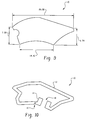
- Figures 9 and 10 depict an irregular shape that corresponds to the shape of the shell of an example BTE hearing aid.
- the aperture of the antenna may be maximized to the space available on the shell of the hearing aid.
- Figure 9 shows the shape of an example BTE hearing aid, including example dimensions.
- Figure 10 shows an example loop antenna having a shape corresponding to the BTE hearing aid shape of Figure 9. The size of the antenna may be +100%, -25% extended.
- FIGs 3 and 4 illustrate two example hearing instrument topologies in which one or more matching networks 30, 30A, 30B are coupled between the loop antenna 10 and a hearing aid system 40. Also illustrated in Figures 3 and 4 is a dotted line that represents the hearing aid shell.
- the matching network(s) 30, 30A, 30B function as an interface between the loop antenna 10 and the communication circuitry 40 in the hearing aid, and may increase the efficiency of the antenna 10.
- the loop antenna 10 may be coupled to the matching network(s) 30, 30A at both antenna feeding points, or alternatively one antenna feeding point may be coupled to a matching network 30, 30A and the other feeding point to ground.
- the matching network 30 is attached to the outer surface of the hearing aid shell, typically on the flex material that carries the antenna as illustrated by the placement of the dotted line.
- a first portion 30A of the matching network is attached to the outer surface of the hearing aid shall and a second portion 30B of the matching network is contained within the hearing aid shell.
- Figure 6 shows a matching network 30 comprising capacitors C1, C2 and inductor L2. Of these three passive elements C1 may be placed on the flex material, such as in the gap 16 shown in Figure 7, whereas elements C2 and L2 may be placed on a circuit board within the hearing aid housing.
- narrow band conjugate matching There are at least two different matching networks for a 50 ohm system.
- One is for narrow band conjugate matching, and the other is for medium bandwidth matching.
- the narrow band conjugate method may be preferable.
- FIG 5 shows an example of a narrow band matching network.
- the matching network includes a capacitor 30 (C1) that is coupled in series between the loop antenna 10 and the hearing aid communications circuitry.
- the capacitor 30 (C1) on flex (such as in the gap 16 shown in Figure 1) has a strong tuning effect on the center working frequency.
- the combination of the radiation resistance, the Q factor of the capacitor 30 (C1) (35 in this example), and the loss from the substrate and conductor determines the antenna bandwidth (e.g., 3 dB)
- Measurements of the prototype antennas described above demonstrated a center frequency that is adjustable around 900 MHz.
- the example 3 dB bandwidth is about 16.95%.
- Figure 6 shows an example of a medium band matching network.
- the matching network includes a first capacitor C1 coupled in series between the loop antenna and the hearing aid communications circuitry, and an LC circuit (C2, L2) coupled in parallel with the loop antenna.
- the LC circuit includes a second capacitor C2 and an inductor L2.
- both capacitors C1, C2 have a Q value of 35, and the inductor has a Q value of 17.
- the example medium band matching circuit shown in Figure 6 can cover 25% 3 dB bandwidth, it may not be preferred for hearing aids due to size and space limitations.
Landscapes
- Engineering & Computer Science (AREA)
- Computer Networks & Wireless Communication (AREA)
- Health & Medical Sciences (AREA)
- General Health & Medical Sciences (AREA)
- Neurosurgery (AREA)
- Otolaryngology (AREA)
- Physics & Mathematics (AREA)
- Acoustics & Sound (AREA)
- Signal Processing (AREA)
- Details Of Aerials (AREA)
- Support Of Aerials (AREA)
- Variable-Direction Aerials And Aerial Arrays (AREA)
- Transceivers (AREA)
Abstract
Description
| Build | A | B | C | D | E | F | G | C_a(pF) | C_b(pF) |
| 1 | 8.5 | 24.0 | 3.75 | 4.0 | 0.8 | 2.0 | 0.25 | 0.5 | 0.7 |
| 2 | 8.5 | 24.0 | 3.75 | 4.0 | 1.0 | 2.0 | 0.25 | 0.5 | 0.7 |
| 3 | 8.5 | 24.0 | 3.75 | 4.0 | 1.2 | 2.0 | 0.25 | 0.35 | 0.7 |
| 4 | 8.5 | 12.0 | 3.75 | 16.0 | 1.2 | 2.0 | 0.25 | 0.5 | 0.7 |
| 5 | 14.5 | 24.0 | 3.75 | 4.0 | 1.2 | 2.0 | 0.25 | 0.5 | 0.55 |
| 6 | 14.5 | 12.0 | 3.75 | 16.0 | 1.2 | 2.0 | 0.25 | 0.6 | 0.70 |
| All sizes in mm |
Claims (18)
- A wireless hearing aid having a communication system positioned within a housing structure for receiving and processing wireless signals and for presenting those signals to a wearer of the hearing aid, the housing structure being positioned in close proximity to the human body of the wearer, the wireless hearing aid comprising:wherein the flexible dielectric is affixed to the housing structure of the wireless hearing aid.a loop antenna configured on a flexible dielectric substrate; anda matching network coupling the loop antenna to the communication system, wherein at least a portion of the matching network is affixed to the flexible dielectric substrate;
- The wireless hearing aid of claim 1, wherein the housing structure includes an inner surface and an outer surface.
- The wireless hearing aid of claim 2, wherein the flexible dielectric substrate is affixed to the inner surface of the housing structure.
- The wireless hearing aid of claim 2, wherein the flexible dielectric substrate is affixed to the outer surface of the housing structure.
- The wireless hearing aid according to one of the claims 1 to 4, wherein the wireless hearing aid is a behind the ear (BTE) hearing aid, and the housing structure is positioned behind the ear of the wearer.
- The wireless hearing aid system according to one of the claims 1 to 5, wherein the wireless hearing aid is a completely in the canal (CIC) hearing aid, an in the canal (ITC) hearing aid, or in the ear (ITE) hearing aid.
- The wireless hearing aid system according to one of the claims 1 to 6, wherein the loop antenna is configured to operate at approximately 900 MHz.
- The wireless hearing aid system according to one of the claims 1 to 7, wherein the loop antenna is positioned along a periphery of a portion of the housing structure so as to maximize the aperture of the loop antenna.
- The wireless hearing aid system according to one of the claims 1 to 8, wherein the received wireless signals are used, in part, to configure the operation of the wireless hearing aid.
- The wireless hearing aid system according to one of the claims 1 to 9, wherein the communication system includes a receiver and a transmitter, the loop antenna being utilized for both receiving wireless signals and transmitting wireless signals.
- The wireless hearing aid system according to one of the claims 1 to 10, wherein the loop antenna includes two portions separated by a pair of gaps, wherein the portion of the matching network that is affixed to the flexible dielectric substrate is positioned within one of the pair of gaps.
- The wireless hearing aid system according to one of the claims 1 to 11, wherein the flexible dielectric substrate is made from polyethylene, FR-4, or Duroid.
- The wireless hearing aid system according to one of the claims 1 to 12, wherein the matching network is a narrow band matching network comprising a capacitor.
- The wireless hearing aid system of claim 13, wherein the capacitor is affixed to the flexible dielectric substrate.
- The wireless hearing aid system according to one of the claims 13 to 14, wherein the loop antenna includes a gap to which the capacitor is connected.
- The wireless hearing aid system according to one of the claims 1 to 15, wherein the matching network is a medium band matching network comprising a pair of capacitors and an inductor.
- The wireless hearing aid system of claim 16, wherein one of the pair of capacitors is connected in series with the loop antenna and the communications system and the other capacitor and the inductor are connected between the loop antenna and ground.
- The wireless hearing aid system of claim 17, wherein the capacitor connected in series with the antenna is affixed to the flexible dielectric substrate and the other capacitor and the inductor are positioned within the housing structure.
Applications Claiming Priority (2)
| Application Number | Priority Date | Filing Date | Title |
|---|---|---|---|
| US51921503P | 2003-11-12 | 2003-11-12 | |
| US519215P | 2003-11-12 |
Publications (2)
| Publication Number | Publication Date |
|---|---|
| EP1531649A2 true EP1531649A2 (en) | 2005-05-18 |
| EP1531649A3 EP1531649A3 (en) | 2008-06-11 |
Family
ID=34435204
Family Applications (1)
| Application Number | Title | Priority Date | Filing Date |
|---|---|---|---|
| EP04027010A Withdrawn EP1531649A3 (en) | 2003-11-12 | 2004-11-12 | Wireless hearing aid system with loop antenna |
Country Status (2)
| Country | Link |
|---|---|
| US (1) | US20050099341A1 (en) |
| EP (1) | EP1531649A3 (en) |
Cited By (10)
| Publication number | Priority date | Publication date | Assignee | Title |
|---|---|---|---|---|
| EP1681903A3 (en) * | 2006-03-30 | 2007-03-28 | Phonak AG | Wireless audio signal receiver device for a hearing instrument |
| WO2007041835A1 (en) * | 2005-10-11 | 2007-04-19 | Gennum Corporation | Electrically small multi-level loop antenna on flex for low power wireless hearing aid system |
| US7548211B2 (en) | 2006-03-30 | 2009-06-16 | Phonak Ag | Wireless audio signal receiver device for a hearing instrument |
| WO2012092973A1 (en) * | 2011-01-07 | 2012-07-12 | Widex A/S | A hearing aid system with a dual mode wireless radio |
| DE102016207844A1 (en) * | 2016-05-06 | 2017-06-08 | Sivantos Pte. Ltd. | hearing Aid |
| US10051388B2 (en) | 2016-09-21 | 2018-08-14 | Starkey Laboratories, Inc. | Radio frequency antenna for an in-the-ear hearing device |
| EP2628210B1 (en) | 2010-10-12 | 2019-01-09 | GN Hearing A/S | A hearing aid comprising an antenna device |
| US10256529B2 (en) | 2016-11-15 | 2019-04-09 | Starkey Laboratories, Inc. | Hearing device incorporating conformal folded antenna |
| EP3404934B1 (en) | 2013-11-11 | 2021-09-29 | GN Hearing A/S | A hearing aid with an antenna |
| EP3343955B1 (en) | 2016-12-29 | 2022-07-06 | Oticon A/s | Assembly for hearing aid |
Families Citing this family (56)
| Publication number | Priority date | Publication date | Assignee | Title |
|---|---|---|---|---|
| ATE508590T1 (en) | 2004-02-19 | 2011-05-15 | Oticon As | HEARING AID WITH ANTENNA FOR RECEIVING AND TRANSMITTING ELECTROMAGNETIC SIGNALS AND SHIELDING BATTERY |
| EP1779704A1 (en) * | 2004-08-18 | 2007-05-02 | Micro Ear Technology, Inc. | Wireless communications adapter for a hearing assistance device |
| EP1782657A1 (en) * | 2004-08-18 | 2007-05-09 | Micro Ear Technology, Inc. | Method and apparatus for wireless communication using an inductive interface |
| US7593538B2 (en) * | 2005-03-28 | 2009-09-22 | Starkey Laboratories, Inc. | Antennas for hearing aids |
| US8041066B2 (en) | 2007-01-03 | 2011-10-18 | Starkey Laboratories, Inc. | Wireless system for hearing communication devices providing wireless stereo reception modes |
| US9774961B2 (en) | 2005-06-05 | 2017-09-26 | Starkey Laboratories, Inc. | Hearing assistance device ear-to-ear communication using an intermediate device |
| US8027638B2 (en) * | 2006-03-29 | 2011-09-27 | Micro Ear Technology, Inc. | Wireless communication system using custom earmold |
| US8208642B2 (en) | 2006-07-10 | 2012-06-26 | Starkey Laboratories, Inc. | Method and apparatus for a binaural hearing assistance system using monaural audio signals |
| US8111150B2 (en) * | 2006-09-08 | 2012-02-07 | Cardiomems, Inc. | Physiological data acquisition and management system for use with an implanted wireless sensor |
| US8934984B2 (en) | 2007-05-31 | 2015-01-13 | Cochlear Limited | Behind-the-ear (BTE) prosthetic device with antenna |
| US8494197B2 (en) * | 2008-12-19 | 2013-07-23 | Starkey Laboratories, Inc. | Antennas for custom fit hearing assistance devices |
| US8699733B2 (en) | 2008-12-19 | 2014-04-15 | Starkey Laboratories, Inc. | Parallel antennas for standard fit hearing assistance devices |
| US8737658B2 (en) | 2008-12-19 | 2014-05-27 | Starkey Laboratories, Inc. | Three dimensional substrate for hearing assistance devices |
| US10142747B2 (en) | 2008-12-19 | 2018-11-27 | Starkey Laboratories, Inc. | Three dimensional substrate for hearing assistance devices |
| US8565457B2 (en) | 2008-12-19 | 2013-10-22 | Starkey Laboratories, Inc. | Antennas for standard fit hearing assistance devices |
| US9420385B2 (en) | 2009-12-21 | 2016-08-16 | Starkey Laboratories, Inc. | Low power intermittent messaging for hearing assistance devices |
| US8503708B2 (en) | 2010-04-08 | 2013-08-06 | Starkey Laboratories, Inc. | Hearing assistance device with programmable direct audio input port |
| DK2725655T3 (en) * | 2010-10-12 | 2021-09-20 | Gn Hearing As | Antenna system for a hearing aid |
| DK2458675T3 (en) * | 2010-10-12 | 2018-01-22 | Gn Hearing As | Hearing aid with antenna |
| US9451353B2 (en) * | 2012-02-08 | 2016-09-20 | Decibullz Llc | Moldable earpiece system |
| US9554219B2 (en) | 2012-07-06 | 2017-01-24 | Gn Resound A/S | BTE hearing aid having a balanced antenna |
| DK201270410A (en) | 2012-07-06 | 2014-01-07 | Gn Resound As | BTE hearing aid with an antenna partition plane |
| DK201270411A (en) | 2012-07-06 | 2014-01-07 | Gn Resound As | BTE hearing aid having two driven antennas |
| US9374650B2 (en) | 2012-07-17 | 2016-06-21 | Starkey Laboratories, Inc. | System and method for embedding conductive traces into hearing assistance device housings |
| US9980062B2 (en) | 2012-12-12 | 2018-05-22 | Sivantos Pte. Ltd. | Hearing aid and method for producing a hearing aid |
| DK2932559T3 (en) * | 2012-12-12 | 2021-12-20 | Sivantos Pte Ltd | MODULAR ANTENNA FOR HEARING AID |
| US9237404B2 (en) | 2012-12-28 | 2016-01-12 | Gn Resound A/S | Dipole antenna for a hearing aid |
| EP2765650A1 (en) * | 2013-02-08 | 2014-08-13 | Nxp B.V. | Hearing aid antenna |
| US10743116B2 (en) * | 2013-04-30 | 2020-08-11 | Starkey Laboratories, Inc. | Small loop antenna with shorting conductors for hearing assistance devices |
| US9635475B2 (en) * | 2013-05-01 | 2017-04-25 | Starkey Laboratories, Inc. | Hearing assistance device with balanced feed-line for antenna |
| US10985447B2 (en) * | 2013-08-02 | 2021-04-20 | Gn Hearing A/S | Antenna device |
| US9237405B2 (en) | 2013-11-11 | 2016-01-12 | Gn Resound A/S | Hearing aid with an antenna |
| US9883295B2 (en) | 2013-11-11 | 2018-01-30 | Gn Hearing A/S | Hearing aid with an antenna |
| US9408003B2 (en) | 2013-11-11 | 2016-08-02 | Gn Resound A/S | Hearing aid with an antenna |
| US9686621B2 (en) | 2013-11-11 | 2017-06-20 | Gn Hearing A/S | Hearing aid with an antenna |
| US10003379B2 (en) | 2014-05-06 | 2018-06-19 | Starkey Laboratories, Inc. | Wireless communication with probing bandwidth |
| US10595138B2 (en) | 2014-08-15 | 2020-03-17 | Gn Hearing A/S | Hearing aid with an antenna |
| US20160330552A1 (en) | 2015-05-07 | 2016-11-10 | Starkey Laboratories, Inc. | Hearing aid bowtie antenna optimized for ear to ear communications |
| US10257624B2 (en) | 2015-08-17 | 2019-04-09 | Starkey Laboratories, Inc. | Hearing aid wireless antenna molded into the device shell |
| US20170064651A1 (en) | 2015-08-28 | 2017-03-02 | Alex Volkov | Synchronization of audio streams and sampling rate for wireless communication |
| DK3148219T3 (en) * | 2015-09-28 | 2021-01-25 | Oticon As | HEARING DEVICE |
| US10440483B2 (en) * | 2015-11-25 | 2019-10-08 | Gn Hearing A/S | Hearing aid with improved wireless communication |
| DK3664473T3 (en) * | 2015-12-14 | 2021-08-16 | Gn Hearing As | Hearing aid |
| US10297910B2 (en) | 2016-10-21 | 2019-05-21 | Starkey Laboratories, Inc. | Hearing device with bowtie antenna optimized for specific band |
| US11011845B2 (en) | 2017-04-21 | 2021-05-18 | Starkey Laboratories, Inc. | Hearing assistance device incorporating a quarter wave stub as a solderless antenna connection |
| US10631109B2 (en) | 2017-09-28 | 2020-04-21 | Starkey Laboratories, Inc. | Ear-worn electronic device incorporating antenna with reactively loaded network circuit |
| EP3471201B1 (en) * | 2017-10-16 | 2021-02-17 | Widex A/S | Antenna for a hearing assistance device |
| US11223109B2 (en) | 2017-10-16 | 2022-01-11 | Widex A/S | Antenna for a hearing assistance device |
| WO2019126317A1 (en) * | 2017-12-21 | 2019-06-27 | Verily Life Sciences Llc | Variable impedance matching networks for stretchable antennas |
| US10979828B2 (en) | 2018-06-05 | 2021-04-13 | Starkey Laboratories, Inc. | Ear-worn electronic device incorporating chip antenna loading of antenna structure |
| US10951997B2 (en) | 2018-08-07 | 2021-03-16 | Starkey Laboratories, Inc. | Hearing device incorporating antenna arrangement with slot radiating element |
| US10785582B2 (en) * | 2018-12-10 | 2020-09-22 | Starkey Laboratories, Inc. | Ear-worn electronic hearing device incorporating an antenna with cutouts |
| US11902748B2 (en) | 2018-08-07 | 2024-02-13 | Starkey Laboratories, Inc. | Ear-worn electronic hearing device incorporating an antenna with cutouts |
| US10931005B2 (en) | 2018-10-29 | 2021-02-23 | Starkey Laboratories, Inc. | Hearing device incorporating a primary antenna in conjunction with a chip antenna |
| US11122376B2 (en) | 2019-04-01 | 2021-09-14 | Starkey Laboratories, Inc. | Ear-worn electronic device incorporating magnetically coupled feed for an antenna |
| CN110534873B (en) * | 2019-09-30 | 2021-07-30 | 维沃移动通信有限公司 | a wearable device |
Family Cites Families (11)
| Publication number | Priority date | Publication date | Assignee | Title |
|---|---|---|---|---|
| CH641619A5 (en) * | 1979-08-30 | 1984-02-29 | Phonak Ag | Hearing-aid with receiver part |
| AT391047B (en) * | 1987-06-26 | 1990-08-10 | Siemens Ag | HEARING DEVICE WITH A CIRCUIT BOARD AND A HEAD COIL |
| EP0584882A1 (en) * | 1992-08-28 | 1994-03-02 | Philips Electronics Uk Limited | Loop antenna |
| US5568516A (en) * | 1993-07-02 | 1996-10-22 | Phonic Ear Incorporated | Very low power cordless headset system |
| US5751820A (en) * | 1997-04-02 | 1998-05-12 | Resound Corporation | Integrated circuit design for a personal use wireless communication system utilizing reflection |
| US6021207A (en) * | 1997-04-03 | 2000-02-01 | Resound Corporation | Wireless open ear canal earpiece |
| US7043041B2 (en) * | 2000-10-04 | 2006-05-09 | Sonionmicrotronic Nederland B.V. | Integrated telecoil amplifier with signal processing |
| US6603440B2 (en) * | 2000-12-14 | 2003-08-05 | Protura Wireless, Inc. | Arrayed-segment loop antenna |
| US20020135523A1 (en) * | 2001-03-23 | 2002-09-26 | Romero Osbaldo Jose | Loop antenna radiation and reference loops |
| TW529205B (en) * | 2001-05-24 | 2003-04-21 | Rfwaves Ltd | A method for designing a small antenna matched to an input impedance, and small antennas designed according to the method |
| US6710744B2 (en) * | 2001-12-28 | 2004-03-23 | Zarlink Semiconductor (U.S.) Inc. | Integrated circuit fractal antenna in a hearing aid device |
-
2004
- 2004-11-11 US US10/986,394 patent/US20050099341A1/en not_active Abandoned
- 2004-11-12 EP EP04027010A patent/EP1531649A3/en not_active Withdrawn
Cited By (26)
| Publication number | Priority date | Publication date | Assignee | Title |
|---|---|---|---|---|
| WO2007041835A1 (en) * | 2005-10-11 | 2007-04-19 | Gennum Corporation | Electrically small multi-level loop antenna on flex for low power wireless hearing aid system |
| WO2007112838A1 (en) * | 2006-03-30 | 2007-10-11 | Phonak Ag | Wireless audio signal receiver device for a hearing instrument |
| US7548211B2 (en) | 2006-03-30 | 2009-06-16 | Phonak Ag | Wireless audio signal receiver device for a hearing instrument |
| US7777681B2 (en) | 2006-03-30 | 2010-08-17 | Phonak Ag | Wireless audio signal receiver device for a hearing instrument |
| US7791551B2 (en) | 2006-03-30 | 2010-09-07 | Phonak Ag | Wireless audio signal receiver device for a hearing instrument |
| EP2257080A1 (en) | 2006-03-30 | 2010-12-01 | Phonak Ag | Wireless audio signal receiver device for a hearing instrument |
| EP2257079A1 (en) | 2006-03-30 | 2010-12-01 | Phonak Ag | Wireless audio signal receiver device for a hearing instrument |
| CN101416531B (en) * | 2006-03-30 | 2013-05-01 | 峰力公司 | Wireless audio signal receiver device for hearing instruments |
| EP1681903A3 (en) * | 2006-03-30 | 2007-03-28 | Phonak AG | Wireless audio signal receiver device for a hearing instrument |
| EP2628210B1 (en) | 2010-10-12 | 2019-01-09 | GN Hearing A/S | A hearing aid comprising an antenna device |
| WO2012092973A1 (en) * | 2011-01-07 | 2012-07-12 | Widex A/S | A hearing aid system with a dual mode wireless radio |
| US9344816B2 (en) | 2011-01-07 | 2016-05-17 | Widex A/S | Hearing aid system and a hearing aid |
| EP3404934B1 (en) | 2013-11-11 | 2021-09-29 | GN Hearing A/S | A hearing aid with an antenna |
| DE102016207844A1 (en) * | 2016-05-06 | 2017-06-08 | Sivantos Pte. Ltd. | hearing Aid |
| US12022263B2 (en) | 2016-09-21 | 2024-06-25 | Starkey Laboratories, Inc. | Radio frequency antenna for an in-the-ear hearing device |
| US10687156B2 (en) | 2016-09-21 | 2020-06-16 | Starkey Laboratories, Inc. | Radio frequency antenna for an in-the-ear hearing device |
| US10051388B2 (en) | 2016-09-21 | 2018-08-14 | Starkey Laboratories, Inc. | Radio frequency antenna for an in-the-ear hearing device |
| US11470430B2 (en) | 2016-09-21 | 2022-10-11 | Starkey Laboratories, Inc. | Radio frequency antenna for an in-the-ear hearing device |
| US10256529B2 (en) | 2016-11-15 | 2019-04-09 | Starkey Laboratories, Inc. | Hearing device incorporating conformal folded antenna |
| US10581144B2 (en) | 2016-11-15 | 2020-03-03 | Starkey Laboratories, Inc. | Hearing device incorporating conformal folded antenna |
| US10886603B2 (en) | 2016-11-15 | 2021-01-05 | Starkey Laboratories, Inc. | Hearing device incorporating conformal folded antenna |
| US11729561B2 (en) | 2016-11-15 | 2023-08-15 | Starkey Laboratories, Inc. | Hearing device incorporating conformal folded antenna |
| US12081947B2 (en) | 2016-11-15 | 2024-09-03 | Starkey Laboratories, Inc. | Hearing device incorporating conformal folded antenna |
| EP3343955B1 (en) | 2016-12-29 | 2022-07-06 | Oticon A/s | Assembly for hearing aid |
| US11765530B2 (en) | 2016-12-29 | 2023-09-19 | Oticon A/S | Assembly for hearing aid |
| US12108221B2 (en) | 2016-12-29 | 2024-10-01 | Oticon A/S | Assembly for hearing aid |
Also Published As
| Publication number | Publication date |
|---|---|
| US20050099341A1 (en) | 2005-05-12 |
| EP1531649A3 (en) | 2008-06-11 |
Similar Documents
| Publication | Publication Date | Title |
|---|---|---|
| US20050099341A1 (en) | Antenna for a wireless hearing aid system | |
| US20070080889A1 (en) | Electrically small multi-level loop antenna on flex for low power wireless hearing aid system | |
| US10667064B2 (en) | ITE hearing aid with improved wireless communication | |
| EP2285138B1 (en) | Hearing aid with antenna for reception and transmission of electromagnetic signals | |
| US12167202B2 (en) | Ear-worn electronic device incorporating antenna with reactively loaded network circuit | |
| EP3316598B1 (en) | Antenna structure for hearing devices | |
| EP3726854B1 (en) | Hearing device with two-half loop antenna | |
| CN110972050B (en) | Hearing device with antenna extending from the hearing device | |
| US20140185848A1 (en) | Dipole antenna for a hearing aid | |
| EP2750409B1 (en) | A dipole antenna for a hearing aid | |
| CN103515694A (en) | Antenna system for a wearable computing device | |
| US11653159B2 (en) | Hearing instrument comprising a battery antenna | |
| EP3236676B1 (en) | Hearing device antenna with optimized orientation | |
| EP3136753B1 (en) | Antenna with flared cross-feed in a hearing assistance device | |
| CN110933580B (en) | Hearing device with antenna function in support structure | |
| US11026027B2 (en) | Ear-worn electronic device incorporating an antenna actively loaded using a non-foster circuit | |
| EP3174314B1 (en) | Ite hearing aid with improved wireless communication | |
| US10869143B2 (en) | Hearing instrument comprising a parasitic battery antenna element | |
| US11076244B2 (en) | Hearing instrument having a digitally tunable antenna | |
| EP4637185A1 (en) | A hearing aid with slot antenna | |
| DK201570757A1 (en) | Ite hearing aid with improved wireless communication |
Legal Events
| Date | Code | Title | Description |
|---|---|---|---|
| PUAI | Public reference made under article 153(3) epc to a published international application that has entered the european phase |
Free format text: ORIGINAL CODE: 0009012 |
|
| AK | Designated contracting states |
Kind code of ref document: A2 Designated state(s): AT BE BG CH CY CZ DE DK EE ES FI FR GB GR HU IE IS IT LI LU MC NL PL PT RO SE SI SK TR |
|
| AX | Request for extension of the european patent |
Extension state: AL HR LT LV MK YU |
|
| PUAL | Search report despatched |
Free format text: ORIGINAL CODE: 0009013 |
|
| AK | Designated contracting states |
Kind code of ref document: A3 Designated state(s): AT BE BG CH CY CZ DE DK EE ES FI FR GB GR HU IE IS IT LI LU MC NL PL PT RO SE SI SK TR |
|
| AX | Request for extension of the european patent |
Extension state: AL HR LT LV MK YU |
|
| 17P | Request for examination filed |
Effective date: 20081113 |
|
| AKX | Designation fees paid |
Designated state(s): AT BE BG CH CY CZ DE DK EE ES FI FR GB GR HU IE IS IT LI LU MC NL PL PT RO SE SI SK TR |
|
| RAP1 | Party data changed (applicant data changed or rights of an application transferred) |
Owner name: GENNUM CORPORATION |
|
| 17Q | First examination report despatched |
Effective date: 20090625 |
|
| STAA | Information on the status of an ep patent application or granted ep patent |
Free format text: STATUS: THE APPLICATION IS DEEMED TO BE WITHDRAWN |
|
| 18D | Application deemed to be withdrawn |
Effective date: 20090603 |