EP1531613A2 - Image forming system - Google Patents
Image forming system Download PDFInfo
- Publication number
- EP1531613A2 EP1531613A2 EP04255045A EP04255045A EP1531613A2 EP 1531613 A2 EP1531613 A2 EP 1531613A2 EP 04255045 A EP04255045 A EP 04255045A EP 04255045 A EP04255045 A EP 04255045A EP 1531613 A2 EP1531613 A2 EP 1531613A2
- Authority
- EP
- European Patent Office
- Prior art keywords
- page number
- image forming
- sheet
- sheets
- forming apparatus
- Prior art date
- Legal status (The legal status is an assumption and is not a legal conclusion. Google has not performed a legal analysis and makes no representation as to the accuracy of the status listed.)
- Withdrawn
Links
- 238000012805 post-processing Methods 0.000 claims abstract description 26
- 238000003780 insertion Methods 0.000 claims description 55
- 230000037431 insertion Effects 0.000 claims description 55
- 238000000034 method Methods 0.000 description 14
- 238000012546 transfer Methods 0.000 description 10
- 239000011521 glass Substances 0.000 description 6
- 210000000078 claw Anatomy 0.000 description 4
- 238000012545 processing Methods 0.000 description 4
- 230000015572 biosynthetic process Effects 0.000 description 3
- 238000004140 cleaning Methods 0.000 description 3
- 230000006835 compression Effects 0.000 description 3
- 238000007906 compression Methods 0.000 description 3
- 230000006870 function Effects 0.000 description 3
- 238000004080 punching Methods 0.000 description 3
- 150000001875 compounds Chemical class 0.000 description 2
- 238000007796 conventional method Methods 0.000 description 2
- 238000005516 engineering process Methods 0.000 description 2
- 238000010586 diagram Methods 0.000 description 1
- 238000009792 diffusion process Methods 0.000 description 1
- 230000005684 electric field Effects 0.000 description 1
- 239000004973 liquid crystal related substance Substances 0.000 description 1
- 230000003287 optical effect Effects 0.000 description 1
- 238000011144 upstream manufacturing Methods 0.000 description 1
Images


Classifications
-
- H—ELECTRICITY
- H04—ELECTRIC COMMUNICATION TECHNIQUE
- H04N—PICTORIAL COMMUNICATION, e.g. TELEVISION
- H04N1/00—Scanning, transmission or reproduction of documents or the like, e.g. facsimile transmission; Details thereof
- H04N1/32—Circuits or arrangements for control or supervision between transmitter and receiver or between image input and image output device, e.g. between a still-image camera and its memory or between a still-image camera and a printer device
- H04N1/32101—Display, printing, storage or transmission of additional information, e.g. ID code, date and time or title
- H04N1/32128—Display, printing, storage or transmission of additional information, e.g. ID code, date and time or title attached to the image data, e.g. file header, transmitted message header, information on the same page or in the same computer file as the image
- H04N1/32133—Display, printing, storage or transmission of additional information, e.g. ID code, date and time or title attached to the image data, e.g. file header, transmitted message header, information on the same page or in the same computer file as the image on the same paper sheet, e.g. a facsimile page header
-
- H—ELECTRICITY
- H04—ELECTRIC COMMUNICATION TECHNIQUE
- H04N—PICTORIAL COMMUNICATION, e.g. TELEVISION
- H04N1/00—Scanning, transmission or reproduction of documents or the like, e.g. facsimile transmission; Details thereof
- H04N1/23—Reproducing arrangements
- H04N1/2307—Circuits or arrangements for the control thereof, e.g. using a programmed control device, according to a measured quantity
- H04N1/2369—Selecting a particular reproducing mode from amongst a plurality of modes, e.g. paper saving or normal, or simplex or duplex
-
- H—ELECTRICITY
- H04—ELECTRIC COMMUNICATION TECHNIQUE
- H04N—PICTORIAL COMMUNICATION, e.g. TELEVISION
- H04N2201/00—Indexing scheme relating to scanning, transmission or reproduction of documents or the like, and to details thereof
- H04N2201/32—Circuits or arrangements for control or supervision between transmitter and receiver or between image input and image output device, e.g. between a still-image camera and its memory or between a still-image camera and a printer device
- H04N2201/3201—Display, printing, storage or transmission of additional information, e.g. ID code, date and time or title
- H04N2201/3225—Display, printing, storage or transmission of additional information, e.g. ID code, date and time or title of data relating to an image, a page or a document
- H04N2201/3232—Display, printing, storage or transmission of additional information, e.g. ID code, date and time or title of data relating to an image, a page or a document of a page, copy or picture number
-
- H—ELECTRICITY
- H04—ELECTRIC COMMUNICATION TECHNIQUE
- H04N—PICTORIAL COMMUNICATION, e.g. TELEVISION
- H04N2201/00—Indexing scheme relating to scanning, transmission or reproduction of documents or the like, and to details thereof
- H04N2201/32—Circuits or arrangements for control or supervision between transmitter and receiver or between image input and image output device, e.g. between a still-image camera and its memory or between a still-image camera and a printer device
- H04N2201/3201—Display, printing, storage or transmission of additional information, e.g. ID code, date and time or title
- H04N2201/3271—Printing or stamping
Landscapes
- Engineering & Computer Science (AREA)
- Multimedia (AREA)
- Signal Processing (AREA)
- General Engineering & Computer Science (AREA)
- Control Or Security For Electrophotography (AREA)
- Accessory Devices And Overall Control Thereof (AREA)
- Collation Of Sheets And Webs (AREA)
Abstract

Description
- The present invention relates to an image forming system including a printer or a copy machine which forms images on a recording medium such as paper.
- In the past, an image forming system including a printer or a copy machine was developed which sequentially printed images on a recording medium (hereinafter referred to as a recording sheet) such as paper or an OHP (over head projector) sheet. Sequential page numbers were printed on each recording sheet.
- In the case that four sheets of documents shown in Fig. 6(a) are copied, in a single sided print mode as shown in Fig. 6(b), page numbers "-1-" to "-4-" are printed on single sides of four recording sheets, while in a double sided printing mode as shown in Fig. 6(c), sequential page numbers "-1-" to "-4-" are printed on double sides of two recording sheets.
- Recently, technology relating to an image forming apparatus which can print not only an image but also the page number is disclosed in
Patent Document 1.Further Patent Document 1 discloses the technology relating to an image forming apparatus in which an operator can reserve whether the page number is printed or not. - However, in the case of counting page numbers in
Patent Document 1, an insertion sheet is considered to be a printed sheet same as a recording sheet, and thereby page number counting is conducted not only for recording sheets but also for inserted sheets. That is, a page number is printed on the inserted sheet, or skipped for the inserted sheet, depending upon whether an image, which includes a blank image and its page number, is to be printed on the inserted sheet, and depending upon whether a page number is to be counted for each page. - Further, in the case of double sided printing, when the page number is not printed on the inserted sheet, necessary is a message saying that page numbers are omitted on front and back, which is very cumbersome, and requires a complicated control.
- Additionally, in the above control, an inserted sheet which does not pass through the image forming apparatus is usually a sheet on which an image is not printed. Accordingly, when a sheet has not passed through the image forming apparatus, the management and control of an assigned page number have not been conducted, and therefore there is no assigned page numbers for every sheet which has not passed through the image forming apparatus. This results in a problem in that page numbering on every page including the inserted sheets is not controlled.
- That is, in an image forming system featuring a function wherein the recording sheets which have not passed through the image forming apparatus are inserted at a predetermined position between plural recording sheets which have passed through the image forming apparatus, it is very problematic to correctly print the sequential page numbers on all the ejected recording sheets, in the ejected order.
- For example, when four sheets of documents shown in Fig. 6(a) are copied by a conventional image forming apparatus, in a single sided print mode, the page number is not printed on the recording sheet inserted in the third order as shown in Fig. 7(a), and further, in a double sided printing mode, the page numbers are not printed on the recording sheet inserted in the second order as shown in Fig. 7(b). Therefore, page numbering not only on the recording sheet but also on the insertion sheet are not controlled, resulting in a problem.
- The objective of the present invention is to print sequential identifying page numbers, based on the single sided print mode or the double sided print mode, in the image forming system including a copying machine and a compound image forming apparatus which prints the image on a recording medium such as paper, while correctly assigning a page number for a single surface or double surfaces of plural recording sheets, as appropriate.
- The objective of the present invention can be attained by the structures described below.
- In an image forming system including an image forming apparatus and a post processing device,
wherein
the image forming apparatus includes;
a printer section which forms an image, while assigning a page number on a single surface or double surfaces of plural recording media fed continuously,
a control means which controls the page number count, in order to assign sequential page numbers on the recording media, and
a selecting device to select one of a single sided print mode, and a double sided print mode, and
the post processing device includes;
a sheet supplying tray for housing the sheets which are to be inserted between a predetermined position of the recording media on which image have been formed,
a conveyance route which conveys the inserted sheets and does not pass them through the image forming apparatus, and
a post processing means for performing post processing steps,
wherein the control means controls to count the page number to be assigned onto continuous and plural sheets of recording media, using a different counting value, based on whether the print mode is for single sided sheets or double sided sheets. - The image forming system described in
structure 1, wherein the counting value is set to "1" for the single side print mode, and "2" for the double side print mode. - The image forming system described in
structure 1, further including an operation section on which a selection input is performed whether the page number is to be counted or skipped for the insertion sheet, and when the control means counts the page number of the insertion sheet, the control means judges whether the page number of the insertion sheet is to be counted or skipped, based on the selection input, and then the control section counts the page number of the insertion sheet, based on the judged result, which is preferable. - According to the present invention, when the insertion sheets, which have not passed through the image forming apparatus and do not carry the fixed image, are inserted at a predetermined position between the successive and plural recording sheets which have passed through the image forming apparatus and carry the fixed images, it is possible to correctly count and print the sequential page numbers, including the page number of the sheets inserted between the successive and plural recording sheets. Further, it is possible to select whether page numbers for the inserted sheets are to be included or not, and thereby, the system becomes more convenient and functional.
-
- Fig. 1 is a cross section of the image forming system which applies to the present invention.
- Fig. 2 is a block diagram of the image forming system which applies to the present invention.
- Fig. 3(a) is a flow chart showing the counting process for page numbers which applies the present invention.
- Fig. 3(b) is a flow chart showing another counting process for page numbers.
- Fig. 4(a) shows an example of the basic operation screen page displayed on a display section shown in Fig. 2.
- Figs. 4(b) - 4(e) show examples of the operation screen pages passing from one or plural steps on the basic operation screen.
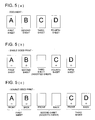
- Fig. 5 explains an arrangement for sequential page numbers, which applies to the present invention.
- Fig. 5(a) shows four sheets of documents to be copied.
- Fig. 5(b) shows an example of the arrangement for the sequential page numbers of sheets on which originals have been copied, when the single side printing mode is selected and an insertion sheet is inserted.
- Fig. 5(c) shows an example of the arrangement for sequential page numbers of sheets on which originals have been copied, when the double sides printing mode is selected and an insertion sheet is inserted.
- Fig. 6 shows the arrangement for sequential page numbers of recording sheets in the conventional method.
- Fig. 6(a) shows four sheets of documents to be copied.
- Fig. 6(b) shows an example of an arrangement for sequential page numbers of sheets on which documents have been copied, when the single side printing mode is selected.
- Fig. 6(c) shows an example of an arrangement for sequential page numbers of sheets on which documents have been copied, when the double sides printing mode is selected.
- Fig. 7 shows another arrangement for sequential page numbers of recording sheets in the conventional method.
- Fig. 7(a) shows an example of an arrangement for sequential page numbers of sheets on which documents have been copied, when the single side printing mode is selected, and an insertion sheet is inserted.
- Fig. 7(b) shows an example of the arrangement for sequential page numbers of sheets on which documents have been copied, when the double sides printing mode is selected and an insertion sheet is inserted.
-
- The embodiment of the present invention will be explained below, referring to the drawings.
- First of all, the structure of
image forming system 1 will be explained, referring to Fig. 1. -
Image forming system 1 includesimage forming apparatus 10, andpost processing device 90 which is post-positioned toimage forming apparatus 10. -
Image forming apparatus 10 is a compound digital machine, employing: - a copy function which reads out the image data from the original, and forms the image on a recording sheet, such as paper, and
- a printer function which receives print data from, for example, a personal computer, and forms the image included in the print data on the recording sheet, and then outputs the image, wherein
-
- Automatic
document feeding device 20 is called an ADF (automatic document feeder), which feedsindividual documents 2, stacked ondocument mounting tray 21, to a reading area ofreading section 30. Further whendocument 2 is a double-sided document, after one side ofdocument 2 is read out,document 2 is flipped over to have the reverse side read by readingsection 30. - Automatic
document feeding device 20 includes feedingrollers 22 which feedindividual documents 2 stacked ondocument mounting tray 21 from the top of the stack, contact roller 23 feeds document 2 ontocontact glass 31 which is the reading area for documents, and guiderollers 24guide document 2 fed by feedingrollers 22 along contact roller 23. - Automatic
document feeding device 20 further includeschangeover claw 25 which changes the feeding direction ofdocument 2 which has passed overcontact glass 31, reversingrollers 26 which flipdocument 2 front to back, andsheet ejecting tray 27 onto which read outdocument 2 is ejected. - Reading
section 30 reads out the image data ofdocument 2 which has been fed byautomatic feeding device 20, and outputs the image data of the above image tomain control section 100, not shown in Fig. 1. - Reading
section 30 includesexposure scanning section 35 which incorporateslight source 33 andmirror 34,line image sensor 36 which receives light reflected fromdocument 2 and outputs electrical signals corresponding to the intensity of the above light,condenser lens 37 which gathers the reflected light fromdocument 2 and directs it to lineimage sensor 36, andvarious mirrors 38 which form an optical route to direct the reflected light frommirror 34 ofexposure scanning section 35 tolight image sensor 36. - When
document 2, fed by automaticdocument feeding device 20 is read out,exposure scanning section 35 moves to the reading area mounted undercontact glass 31 and stops there, whiledocument 2 is fed ontoexposure scanning section 35 by contact roller 23, wheredocument 2 is read out. Whendocument 2, mounted onplaten glass 32 is read out,document 2, which is in a holding state, is read out byexposure scanning section 35 which moves from left to right underplaten glass 32. -
Printer section 40 forms the image, shown by the image data, onto the recording sheet by an electronic photographic process.Printer section 40 featureslaser unit 42 which radiates laser rays changing on/off, based on the image data. -
Further printer section 40 includesphotoconductor 43 on which an electrostatic latent image is formed, and further includes chargingdevice 44, developingdevice 45, transfer device 46, separating device 47, and cleaningdevice 48, all of which are arranged aroundphotoconductor 43. -
Cylindrical photoconductor 43 is rotated by a driving section, which is not illustrated, in the direction shown by arrow A in Fig. 1. Chargingdevice 44 evenly chargesphotoconductor 43 by corona discharge. - When the surface of
photoconductor 43, which is evenly charged, is scanned by the laser light changing from on to off based on the image data, an electrostatic latent image is formed on the surface ofphotoconductor 43. - Developing
device 45 creates the toner image from the electrostatic latent image formed on the surface ofphotoconductor 43. - Transfer device 46 impresses
photoconductor 43 with an electric field, and thereby the toner images on the surface ofphotoconductor 43 is transferred onto the recording sheet with electrostatic action. Separating device 47 repels the recording sheet fromphotoconductor 4 by opposing electrical charges. - Using a blade,
cleaning device 48 scrapes away and recovers any remaining toner onphotoconductor 43 after transfer. The recovered toner is returned to developingdevice 45 through a route which is not illustrated. Fixingdevice 49 presses and heats the toner image on the recording sheet, and thereby the toner image is fixed on the recording sheet. -
Sheet feeding section 60 features pluralsheet feeding cassettes 61. Various sized and types of sheets are accommodated in pluralsheet feeding cassettes 61. Firstsheet feeding roller 62 feeds individual recording sheets toconveyance section 70 from the top of the stacked sheets accommodated insheet feeding cassette 61. -
Conveyance section 70 includesnormal route 70a wherein the recording sheet conveyed fromsheet feeding cassette 61 passes over the transfer area betweenphotoconductor 43 and transfer device 46, after which the recording sheet passes through fixingdevice 49 and is ejected to the outside of the apparatus (to whichpost processing device 90 is connected), andreverse route 70b whereby the recording sheet having passed through fixingdevice 49 is flipped, after which upstream of the transfer area, the recording sheet again followsnormal route 70a. - When the recording sheet passes through
normal route 70a, images are formed on one side of the recording sheet, and after the recording sheet is passed through reversingroute 70b, when the recording sheet again passes throughnormal route 70a, images are also formed on the other side of the recording sheet. - At the downstream with respect to the sheet conveyance direction of fixing
device 49, claw 75 which changes the route of recording sheet is positioned. When route change claw is in the horizontal position shown by the dotted line in Fig. 1, the ejecting direction is set straight, and thereby the fixed recording sheet is fed in the direction shown by line C in Fig. 1, and is ejected to postprocessing device 90. Whenclaw 75 is changed to a sloping position shown in a solid line in Fig. 1, recording sheet is fed in the direction shown by line D in Fig. 1. - After the image formation on the front in the double sided printing operation is conducted, the recording sheet, conveyed in the direction shown by line D, is directly conveyed to reverse
route 70b, and then the image formation on the back of the sheet is conducted. In single sided printing operation, in a case that the recording sheet after the image formation is reversed and ejected, when the top end of the recording sheet, conveyed in the direction shown by line D, reaches reversingrollers 76 arranged at a branching point, reversingrollers 76 are driven in the reverse direction. Therefore, the recording sheet is conveyed in the direction shown by line F, and is ejected to postprocessing device 90 in a face down orientation, in which the front and back sides of the sheet are reversed. -
Post processing device 90inserts insertion sheets 4 between the plural recording sheets outputted fromimage forming apparatus 10, and also insertsinsertion sheets 4 before and after the plural recording sheets outputted fromimage forming apparatus 10, for sorting the chapters or for the cover sheets. - Further,
post processing device 90 is provided with post processing means 91, including
punchingdevice 91a for punching a hole on the inserted sheets, and
stapler 91b for stapling the recorded sheets, and
sheet supplying tray 5 forhousing insertion sheet 4 - Post processing means 91 stacks the recording sheets or
insertion sheets 4 in a stack section 91C in accordance with their conveyed order, and when the required number of sheets are stacked, post processing means 91 conducts stapling or punching based on the inputted instructions, and ejects the produced sheets ontoejection tray 92.Insertion sheets 4 which are stocked onpost processing device 90 are conveyed to post processing means 91, via conveyance route G which does not pass through the image forming apparatus. - Next, the electrical structure of
image forming apparatus 10 will be explained while referring to Fig. 2. Readingsection 30 is provided withline image sensor 36, andscanner control section 210.Line image sensor 36 is represented by CCD (a charge coupled device), which reads out the image data fromdocument 2 mounted onplaten glass 32 via an photoelectric transfer, and outputs it toreadout processing section 101 ofmain control section 100.Scanner control section 210 controls lighting oflight source 33, and movement ofexposure scanning section 35. -
ADF control section 215 controls operations such as automatic document feed which is conducted by automaticdocument feeding device 20. -
Operation display section 220 is provided withdisplay section 221 formed of a liquid crystal display,operation section 222 which is formed of touch sensitive switches and the other types of switches which are arranged on the display, andoperation control section 223 which controls the operations ofdisplay section 221 andoperation section 222, whereby, various operations are input byoperation display section 220 and various information is displayed onoperation display section 220. -
Operation control section 223 displays various operational displays D1-D5 shown in Fig. 4 ondisplay section 221, to allow input of various operations. -
Printer section 40 is provided withlaser generator unit 42 andprinter control section 230.Printer control section 230controls charging device 44, transfer section 46, the voltage application to separating device 47, the rotation ofphotoconductor 43, developingdevice 45,cleaning device 48, fixingdevice 49,sheet feeding device 60,transfer section 70, as well as the rotation of a polygon mirror. -
Scanner control section 210,ADF control section 215,operation control section 223, andprinter control section 230 are provided with CPU (central processing unit), ROM (read only memory), and RAM (random access memory), none of which are illustrated, and perform each control by conducting program stored in each respective ROM. -
Main control section 100 is provided withreadout processing section 101,DRAM control section 102,compression section 103,expansion section 104,image memory 105, writingsection 106,non-volatile memory 107, andimage control section 110. -
Readout processing section 101 performs an A/D (analog/digital) transfer process, an enlarging process, a mirrored image process, and a binarization process by an error diffusion. -
Compression section 103 compresses the binary image data, andexpansion section 104 expands the compressed image data to the form of the original image data. -
Image memory 105 is provided withcompression memory 105a in which the compressed image data are accumulated. -
Writing section 106 outputs the image data, which were read out fromimage memory 105 and expanded, tolaser unit 42 in timing with the operation ofprinter section 40. -
DRAM control section 102 performs the timing controls for the read/write and refresh process forimage memory 105 being a dynamic RAM, and further performs the timing control for compressing image data and storing the image data inimage memory 105, and also for reading out the compressed data fromimage memory 105 and expanding the compressed data. -
Image control section 110, which is provided with a CPU, ROM and RAM, controls the overall operation ofimage forming apparatus 10, in such a way that the CPU performs the program stored in ROM, and thereby controls the flow of image data, and the reservation and the performance of the jobs. Specifically,image control section 110 performs the page number counting process which is shown in the flowchart of Fig. 3(a) or 3 (b). -
Non-volatile memory 107 stores user data and system data, even when power supply is cut off. - Next, the operation of
image forming apparatus 1 will be explained, while referring to Fig. 3. The operation explained below is performed byimage control section 110 which is a control means of the present invention. - The page number counting process shown in the flowchart of Fig. 3(a) will be explained below.
- The user previously determines the position (for example, a third sheet) where
insertion sheet 4 should be inserted among the plural sheets ejected ontosheet ejection tray 92, using operation screen D5, shown in Fig. 4(e). That is, the user previously touches selection button D13 for setting the output of basic operation screen D1 so that operation screen D5 is displayed, then the user previously touches selection button D51 for selecting the sheet insertion on operation screen D5 and inputs insertion instruction ofinsertion sheet 4, and further, the user previously inputs the desired position (which is a page number) ofinsertion sheet 4 into input column D52, by using the ten-key pad. - Firstly, the total page number count is selected, depending on whether a recording medium, which will be ejected onto
ejection tray 92, is the recording sheet conveyed fromimage forming apparatus 10, or isinsertion sheet 4, directly conveyed frompost processing device 90 without passing through image forming apparatus 10 (in step S10). The sequential page numbers are printed only on the recording sheets, not oninsertion sheet 4. - At this moment, the total page number count is a datum for counting the page number which is to be printed on the respective recording sheet. The total page number count is stored in an internal memory, which is not illustrated but exists in
image control section 110, or is stored innon-volatile memory 107. - In step S10, when the recording medium is the recording sheet and is not insertion sheet 4 (which is "NO" of step S10), the page number to be printed on said recording sheet is equal to ("1" + the present page number count) (step S11).
- While in step S10, when the recording medium is insertion sheet 4 (which is "YES" of step S10), it is judged whether double sided printing mode has been selected or not (step S12), and when double sided printing mode has not been selected, that is, when only single sided printing mode has been selected (which is "NO" of step S12), the page number to be printed on the recording sheet is equal to {the value (that is "1") corresponding to the single side page number of said
insertion sheet 4 + the present page number count} (in step 13). - For example, as shown in Fig. 5(b), in the case that four sheets of documents shown in Fig. 5(a) are single side printed, the page number to be printed on the fourth recording sheet (which is the fourth page) which will be ejected after
insertion sheet 4 being the third sheet (which is the third page) is "4", because (the page number count "2" + the page number "1" of single sided printing ofinsertion sheet 4 which is the third sheet + additional "1") is equal to "4". - In this case, the user can select double sided printing mode or single sided printing mode, by touching selection buttons D11 of basic operation screen D1, shown in Fig. 4(a).
- In step S12, if the double sided printing mode ("YES" of step S12) is set, the page number to be printed on the recording sheet is equal to {the page number "2" of the double sided print of said
insertion sheet 4 + the present page number count ("2")} (in step S14). - For example, as shown in Fig. 5(c), in the case that four sheets of documents shown in Fig. 5(a) are double side printed, the page number, to be printed on the third recording sheet (which are the fifth page and sixth page) which will be ejected after
insertion sheet 4 being the second sheet (which is the third page and the fourth page), is "5". Because {the present page number count "2" (which is for the rear page of the first sheet) + the page number "2" of double sided printing ofinsertion sheet 4 + additional "1"} is equal to "5". Further, the page number to be printed on the rear surface of the third recording sheet is "6", because (the above value "5" + additional "1") is "6". - In this case,
image control section 110 will perform the page number counting process shown in the flowchart of Fig. 3(b), instead of the page number counting process shown in Fig. 3(a). - Next the page number counting process shown in the flowchart of Fig. 3(b) will be explained below.
- The user can previously determine the position (for example, a third sheet) where
insertion sheet 4 should be inserted among the plural sheets ejected onsheet ejection tray 92, using operation screen D5 shown in Fig. 4(e). That is, the user touches selection button D13 of basic operation screen D1 so that operation screen D5 is displayed, then the user touches selection button D51 on operation screen D5 and inputs insertion instruction forinsertion sheet 4, and further, the user previously inputs the insertion position (which is a page number) forinsertion sheet 4 into input column D52, by using the ten-key pad. - Firstly, the configuration for the page number count is changed, depending on whether the recording medium which will be ejected onto
ejection tray 92 is the recording sheet conveyed fromimage forming apparatus 10, or isinsertion sheet 4, which is directly conveyed frompost processing device 90 without passing through image forming apparatus 10 (step 20), and further instep S 20, in the case thatinsertion sheet 4 is ejected onto sheet ejection tray 92 (that is YES of step S20), in step S22, the configuration for the page number count is changed, depending on whether a page number print skip mode is selected or not. The sequential page numbers are printed only on the recording sheet, not oninsertion sheet 4. - The user selects the page number print skip mode by the procedure described below. That is, the user touches selection button D12 of basic operation screen D1 to display operation screen D2. Next, the user touches selection button D21 of operation screen D2 to display operation screen D3, after which, the user touches selection button D31 of operation screen D3 to display operation screen D4. Then the user touches "the count step" button from the available buttons D41 so that the selection instruction of the page number print skip mode is sent to image
control section 110. In this case, if the user touches "the count" button from the available buttons D41, the page number print skip mode is released, and the page number ofinsertion sheet 4 is coupled with the total page number count (see step S25 and Figs. 7(a) and 7(b)). - In step S20, when the recording medium which is given the page number is the recording sheet, and not insertion sheet 4 (No of Step S20), the page number to be printed on the recording sheet is equal to (the present page number + "1") (in Step S21).
- In step S20, when the recording medium is insertion sheet 4 (YES of step S20), and further, in step S22, when the page print skip mode is not selected (NO of step S22), and still further, it is judged whether the double sided printing is selected or not (step S23), and if the double sided printing mode has not been selected, that is, if only single sided printing has been selected (NO of step S23), the page number to be printed on the recording sheet is equal to {the present page number count + the value (that is "1") corresponding to the single side page number of said insertion sheet 4} (shown in Step S21).
- In this case, the user can select double side printing mode or single side printing mode, by touching selection buttons D11 of basic operation screen D1 shown in Fig. 4(a).
- Further in step S23, the double side printing mode has been established ("YES" of step S23), the page number to be printed on the recording sheet is equal to (the present page number count + the value "2" corresponding to the page number of the double side pages of said insertion sheet 4) (in step S24).
- In step S22, when the page number print skip mode has been selected (YES of step S22), the page number is (the present page number count + "0") and the present page number count is still maintained (step S25). Therefore, the page number is counted without including the page number of the insertion sheet.
- As explained above, in
image forming system 1, includingimage forming apparatus 10 andpost processing device 90, wherein insertion sheet 4 (on which the image is not printed) can be directly inserted to the predetermined position among the plural recording sheets, inpost processing device 90, without passing through image forming apparatus 10 (fixing device 49),image forming system 1 can correctly perform arrangement of the page number on the plural recording sheets includinginsertion sheet 4, depending upon whether the number of insertion sheets is included, and further depending upon whether the single page printing mode or the double sides printing mode is established. - Accordingly, when insertion sheet 4 (which is a sheet having no printed image) is inserted at a predetermined position of the plural recording sheets (which have printed images), through the conveyance route which does not pass through image forming apparatus 10 (fixing device 49), it is thereby possible to print sequential page numbers which includes numbers for the
insertion sheets 4, on continuous plural recording sheets. Further, it is possible to select whether the number ofinsertion sheets 4 is included or not, and thereby it becomes very convenient and functional. - The description of the present embodiment shows an example of the image forming system of the present invention, however the invention is not limited to this embodiment. The detailed structure and operation of
image forming system 1 of the present embodiments can be appropriately changed within the scope which has no departure from the present invention.
Claims (3)
- An image forming system, comprising:whereinan image forming apparatus; anda post processing device;
the image forming apparatus includes;
a printer section which forms an image, while assigning a page number on a single surface or double surfaces of plural recording media fed continuously,
a control means which controls a page number count, in order to assign sequential page numbers on the recording media, and
a selecting device to select one of a single sided print mode and a double sided print mode, and
the post processing device includes;
a sheet supplying tray for housing the sheets which are to be inserted between a predetermined position of the recording media on which images have been formed,
a conveyance route which conveys the inserted sheets and does not pass them through the image forming apparatus, and
a post processing means for performing post processing steps,
wherein the control means controls to count the page number to be assigned onto the plural sheets of recording media fed continuously, using a different counting value, based on whether the print mode is for single sided sheets or double sided sheets. - The image forming system in claim 1, wherein the counting value is set to "1" for the single side print mode, and "2" for the double side print mode.
- The image forming system in structure 1, further comprising an operation section on which a selection input is performed whether the page number is to be counted or skipped for the insertion sheet, and
when the control means counts the page number of the insertion sheet, the control means judges whether the page number of the insertion sheet is to be counted or skipped, based on the selection input, and then the control section counts the page number of the insertion sheet, based on the judged result.
Applications Claiming Priority (4)
| Application Number | Priority Date | Filing Date | Title |
|---|---|---|---|
| JP2003385518 | 2003-11-14 | ||
| JP2003385518 | 2003-11-14 | ||
| JP2004207168 | 2004-07-14 | ||
| JP2004207168A JP2005161837A (en) | 2003-11-14 | 2004-07-14 | Image formation system |
Publications (2)
| Publication Number | Publication Date |
|---|---|
| EP1531613A2 true EP1531613A2 (en) | 2005-05-18 |
| EP1531613A3 EP1531613A3 (en) | 2006-07-26 |
Family
ID=34436992
Family Applications (1)
| Application Number | Title | Priority Date | Filing Date |
|---|---|---|---|
| EP04255045A Withdrawn EP1531613A3 (en) | 2003-11-14 | 2004-08-20 | Image forming system |
Country Status (3)
| Country | Link |
|---|---|
| US (1) | US7025452B2 (en) |
| EP (1) | EP1531613A3 (en) |
| JP (1) | JP2005161837A (en) |
Families Citing this family (6)
| Publication number | Priority date | Publication date | Assignee | Title |
|---|---|---|---|---|
| JP2006218850A (en) * | 2005-01-17 | 2006-08-24 | Ricoh Co Ltd | Recorder |
| JP4730103B2 (en) * | 2006-01-13 | 2011-07-20 | コニカミノルタビジネステクノロジーズ株式会社 | Image forming system, image forming apparatus, and program |
| JP5054469B2 (en) * | 2007-09-04 | 2012-10-24 | 株式会社リコー | Image forming apparatus |
| US8090284B2 (en) * | 2008-06-23 | 2012-01-03 | Kyocera Mita Corporation | Image forming apparatus and printing control method |
| JP4981878B2 (en) * | 2009-11-25 | 2012-07-25 | コニカミノルタビジネステクノロジーズ株式会社 | Image forming system |
| JP2015201806A (en) * | 2014-04-10 | 2015-11-12 | キヤノン株式会社 | Image reader |
Citations (4)
| Publication number | Priority date | Publication date | Assignee | Title |
|---|---|---|---|---|
| EP0806721A1 (en) * | 1996-05-09 | 1997-11-12 | Fuji Xerox Co., Ltd. | Print control system and method |
| US20020149794A1 (en) | 2001-03-27 | 2002-10-17 | Yoshiki Yoshioka | Image forming apparatus for collective printing and collective printing method |
| EP1333384A2 (en) * | 2002-02-01 | 2003-08-06 | Canon Kabushiki Kaisha | Document processing apparatus and method |
| US20030184806A1 (en) | 2002-02-06 | 2003-10-02 | Canon Kabushiki Kaisha | Displaying of print layout |
Family Cites Families (8)
| Publication number | Priority date | Publication date | Assignee | Title |
|---|---|---|---|---|
| JP3016505B2 (en) * | 1995-05-11 | 2000-03-06 | 富士ゼロックス株式会社 | Image forming device |
| US6466336B1 (en) * | 1999-08-30 | 2002-10-15 | Compaq Computer Corporation | Method and apparatus for organizing scanned images |
| US20010044868A1 (en) * | 2000-05-17 | 2001-11-22 | Tomas Roztocil | System and method for visual representation and manipulation of tabs on a production printer |
| JP2001347735A (en) * | 2000-06-09 | 2001-12-18 | Konica Corp | Imaging device |
| JP4393076B2 (en) * | 2002-02-20 | 2010-01-06 | キヤノン株式会社 | Image processing method and apparatus |
| JP4035345B2 (en) * | 2002-02-21 | 2008-01-23 | キヤノン株式会社 | Print control program, print control method, and information processing apparatus |
| JP4313974B2 (en) * | 2002-02-21 | 2009-08-12 | キヤノン株式会社 | Print control program, print control method, and information processing apparatus |
| GB2390716B (en) * | 2002-07-11 | 2005-06-29 | Software 2000 Ltd | Printer driver |
-
2004
- 2004-07-14 JP JP2004207168A patent/JP2005161837A/en active Pending
- 2004-08-20 EP EP04255045A patent/EP1531613A3/en not_active Withdrawn
- 2004-08-25 US US10/925,739 patent/US7025452B2/en active Active
Patent Citations (4)
| Publication number | Priority date | Publication date | Assignee | Title |
|---|---|---|---|---|
| EP0806721A1 (en) * | 1996-05-09 | 1997-11-12 | Fuji Xerox Co., Ltd. | Print control system and method |
| US20020149794A1 (en) | 2001-03-27 | 2002-10-17 | Yoshiki Yoshioka | Image forming apparatus for collective printing and collective printing method |
| EP1333384A2 (en) * | 2002-02-01 | 2003-08-06 | Canon Kabushiki Kaisha | Document processing apparatus and method |
| US20030184806A1 (en) | 2002-02-06 | 2003-10-02 | Canon Kabushiki Kaisha | Displaying of print layout |
Also Published As
| Publication number | Publication date |
|---|---|
| JP2005161837A (en) | 2005-06-23 |
| US7025452B2 (en) | 2006-04-11 |
| EP1531613A3 (en) | 2006-07-26 |
| US20050105930A1 (en) | 2005-05-19 |
Similar Documents
| Publication | Publication Date | Title |
|---|---|---|
| US7894094B2 (en) | System and method for image rotation | |
| JP3532048B2 (en) | Digital copier | |
| JPH0968895A (en) | Image forming device and method therefor | |
| JPH01273070A (en) | Recorder | |
| US7025452B2 (en) | Image forming system | |
| US5517295A (en) | Image forming apparatus having composite modes selectable during jam recovery | |
| US20090244623A1 (en) | Image forming apparatus | |
| JPH1127435A (en) | Image forming device | |
| JP3645188B2 (en) | Image forming apparatus | |
| JP2003101757A (en) | Image forming apparatus | |
| JP3214502B2 (en) | Copier | |
| JP2844651B2 (en) | Recording device | |
| JP2000335051A (en) | Imaging apparatus | |
| JP2903532B2 (en) | Recording device | |
| JP4076827B2 (en) | Image forming apparatus | |
| JP3150333B2 (en) | Image reading device | |
| JP2003244366A (en) | Image forming apparatus | |
| JP2005024750A (en) | Image forming apparatus | |
| JPH07199566A (en) | Image recorder | |
| JPH02156264A (en) | Enlargement/reduction recording method and recorder | |
| JPH047672A (en) | Image-forming/storing device | |
| JPH09295442A (en) | Image forming apparatus | |
| JPH06324537A (en) | Image recording device | |
| JP2003330343A (en) | Image forming device | |
| JPH043261A (en) | Image formation storage device |
Legal Events
| Date | Code | Title | Description |
|---|---|---|---|
| PUAI | Public reference made under article 153(3) epc to a published international application that has entered the european phase |
Free format text: ORIGINAL CODE: 0009012 |
|
| AK | Designated contracting states |
Kind code of ref document: A2 Designated state(s): AT BE BG CH CY CZ DE DK EE ES FI FR GB GR HU IE IT LI LU MC NL PL PT RO SE SI SK TR |
|
| AX | Request for extension of the european patent |
Extension state: AL HR LT LV MK |
|
| PUAL | Search report despatched |
Free format text: ORIGINAL CODE: 0009013 |
|
| AK | Designated contracting states |
Kind code of ref document: A3 Designated state(s): AT BE BG CH CY CZ DE DK EE ES FI FR GB GR HU IE IT LI LU MC NL PL PT RO SE SI SK TR |
|
| AX | Request for extension of the european patent |
Extension state: AL HR LT LV MK |
|
| 17P | Request for examination filed |
Effective date: 20061016 |
|
| 17Q | First examination report despatched |
Effective date: 20061124 |
|
| AKX | Designation fees paid |
Designated state(s): DE GB |
|
| STAA | Information on the status of an ep patent application or granted ep patent |
Free format text: STATUS: THE APPLICATION IS DEEMED TO BE WITHDRAWN |
|
| 18D | Application deemed to be withdrawn |
Effective date: 20150725 |