EP1531513A2 - Combination nickel foam expanded nickel screen electrical connection supports for solid oxide fuel cells - Google Patents
Combination nickel foam expanded nickel screen electrical connection supports for solid oxide fuel cells Download PDFInfo
- Publication number
- EP1531513A2 EP1531513A2 EP04011641A EP04011641A EP1531513A2 EP 1531513 A2 EP1531513 A2 EP 1531513A2 EP 04011641 A EP04011641 A EP 04011641A EP 04011641 A EP04011641 A EP 04011641A EP 1531513 A2 EP1531513 A2 EP 1531513A2
- Authority
- EP
- European Patent Office
- Prior art keywords
- row
- fuel cells
- bundle
- mesh
- nickel
- Prior art date
- Legal status (The legal status is an assumption and is not a legal conclusion. Google has not performed a legal analysis and makes no representation as to the accuracy of the status listed.)
- Granted
Links
Images




Classifications
-
- H—ELECTRICITY
- H01—ELECTRIC ELEMENTS
- H01M—PROCESSES OR MEANS, e.g. BATTERIES, FOR THE DIRECT CONVERSION OF CHEMICAL ENERGY INTO ELECTRICAL ENERGY
- H01M8/00—Fuel cells; Manufacture thereof
- H01M8/02—Details
- H01M8/0202—Collectors; Separators, e.g. bipolar separators; Interconnectors
- H01M8/023—Porous and characterised by the material
- H01M8/0232—Metals or alloys
-
- H—ELECTRICITY
- H01—ELECTRIC ELEMENTS
- H01M—PROCESSES OR MEANS, e.g. BATTERIES, FOR THE DIRECT CONVERSION OF CHEMICAL ENERGY INTO ELECTRICAL ENERGY
- H01M8/00—Fuel cells; Manufacture thereof
- H01M8/02—Details
- H01M8/0202—Collectors; Separators, e.g. bipolar separators; Interconnectors
- H01M8/0247—Collectors; Separators, e.g. bipolar separators; Interconnectors characterised by the form
-
- H—ELECTRICITY
- H01—ELECTRIC ELEMENTS
- H01M—PROCESSES OR MEANS, e.g. BATTERIES, FOR THE DIRECT CONVERSION OF CHEMICAL ENERGY INTO ELECTRICAL ENERGY
- H01M8/00—Fuel cells; Manufacture thereof
- H01M8/02—Details
- H01M8/0202—Collectors; Separators, e.g. bipolar separators; Interconnectors
- H01M8/0247—Collectors; Separators, e.g. bipolar separators; Interconnectors characterised by the form
- H01M8/0254—Collectors; Separators, e.g. bipolar separators; Interconnectors characterised by the form corrugated or undulated
-
- H—ELECTRICITY
- H01—ELECTRIC ELEMENTS
- H01M—PROCESSES OR MEANS, e.g. BATTERIES, FOR THE DIRECT CONVERSION OF CHEMICAL ENERGY INTO ELECTRICAL ENERGY
- H01M8/00—Fuel cells; Manufacture thereof
- H01M8/24—Grouping of fuel cells, e.g. stacking of fuel cells
- H01M8/2404—Processes or apparatus for grouping fuel cells
-
- H—ELECTRICITY
- H01—ELECTRIC ELEMENTS
- H01M—PROCESSES OR MEANS, e.g. BATTERIES, FOR THE DIRECT CONVERSION OF CHEMICAL ENERGY INTO ELECTRICAL ENERGY
- H01M8/00—Fuel cells; Manufacture thereof
- H01M8/24—Grouping of fuel cells, e.g. stacking of fuel cells
- H01M8/241—Grouping of fuel cells, e.g. stacking of fuel cells with solid or matrix-supported electrolytes
- H01M8/2425—High-temperature cells with solid electrolytes
- H01M8/243—Grouping of unit cells of tubular or cylindrical configuration
-
- Y—GENERAL TAGGING OF NEW TECHNOLOGICAL DEVELOPMENTS; GENERAL TAGGING OF CROSS-SECTIONAL TECHNOLOGIES SPANNING OVER SEVERAL SECTIONS OF THE IPC; TECHNICAL SUBJECTS COVERED BY FORMER USPC CROSS-REFERENCE ART COLLECTIONS [XRACs] AND DIGESTS
- Y02—TECHNOLOGIES OR APPLICATIONS FOR MITIGATION OR ADAPTATION AGAINST CLIMATE CHANGE
- Y02E—REDUCTION OF GREENHOUSE GAS [GHG] EMISSIONS, RELATED TO ENERGY GENERATION, TRANSMISSION OR DISTRIBUTION
- Y02E60/00—Enabling technologies; Technologies with a potential or indirect contribution to GHG emissions mitigation
- Y02E60/30—Hydrogen technology
- Y02E60/50—Fuel cells
Definitions
- This invention relates generally to inexpensive high strength, flexible, thin, improved electrical connectors and supports for tubular solid oxide electrolyte fuel cells in a fuel cell generator.
- These cylindrical cells are usually placed in a square pitch, series-parallel connected array, wherein the air electrode of one cell is connected to the fuel electrode of the adjacent series-connected cell by a plated interconnection strip and a strip of 80% to 95% porous sintered nickel felt, which is about 0.1 inch (0.25 cm) thick.
- Other nickel felts provide parallel connections between the fuel electrodes of adjacent cells.
- the series path is essential for the generation of a practical DC stack voltage.
- the parallel connections provide paths by which the current can circumnegotiate any defective open circuit cells.
- cell bundles the primary subassemblies from which a solid oxide fuel cell generator is formed are called "cell bundles".
- cell bundles contain twenty-four cells on an 8x3 cell matrix. Eight cells are series connected to form one row of a three-row bundle. The three rows are connected in parallel through the connection of each cell in the row with the adjacent cell in the next row. Between the nickel plated interconnection strip of one cell and the nickel fuel electrode of the next cell in a row, any two cells are presently series connected by a nickel felt of a rectangular cross-section (approximately 10 mm x 14 mm). Parallel connection is also currently accomplished by similar felt strips. In this case, the felts connect the fuel electrodes of adjacent cells.
- U.S. Patent Specification No. 5,273,838 (Draper/Zymboly) eliminated one nickel felt connector from each group of four cells, where alternate cells of a first row had no electrical connection of their interconnections to cells in an adjacent row. This design helped to eliminate the potential for bowing when using newer, longer one meter cells. This design may, however, decrease the overall strength of the twenty-four cell subassemblies.
- the strips could also be made of a solid nickel foil or a composite of foil and porous felt; they could also have two opposing fuel cell conforming surface, as shown in Fig. 3 of that patent.
- the use of fibrous felts still allowed potential densification during prolonged use. Additionally, it was difficult to fashion such felts to exact dimensions, and the felts retailed a springiness. Conversely, the use of foils did not provide adequate strength, and prevented the required infiltration of he bundle with hot air during the drying process, which is an important feature of bundle manufacture.
- metal foams have been used as a heat exchange media, as taught be D.P. Haack et al. in "Novel Lightweight Metal Foam Heat Exchangers", 2001 ASME Congress Proceedings, New York, November 2001; and as fuel cell components for water management, heat exchange, flow plates and catalyst substrate for reformers as described at www.porvairfuelcells.com, allowing faster transfer of heat energy than in ceramic structures.
- Metals used include platinum, copper, steel, nickel, silver, cobalt, rhodium and titanium, among others. Ceramic foam filters have also been taught in U.S. Patent Specification No. 5,456,833 (Butcher et al.)
- What is needed is a highly porous nickel based electrical connector/support to conform to and support all contacting fuel cells, as well as to connect all contacting fuel cells electrically, where connector to nickel plated interconnection contact strength is much improved and where electrical conductivity at the same contact point is also much improved.
- the connector/support must be strong, but it must also be possible to increase even more the desired flexibility by selection of an appropriate combination form or shape, without use of metal felts.
- a solid oxide fuel cell assembly comprising rows of fuel cells, each having an outer interconnection and an outer electrode, disposed next to each other with corrugated electrically conducting metal mesh between each row of cells, the corrugated mesh having a top crown portion and a bottom shoulder portion, where a flexible open cell nickel foam is disposed between and contacts both the crown portion and the outer interconnections of the fuel cells in a first row, and where the shoulder portion of the mesh directly contacts the outer electrodes of the fuel cells in a second row, said nickel foam and mesh electrically connecting each row of fuel cells, said mesh having a single corrugation with a top portion between fuel cells in a row and where there are no metal felt connections between any fuel cells.
- the invention also comprises a plurality of solid oxide fuel cell assemblies comprising a fuel cell bundle, each bundle comprising a first row of spaced apart, axially elongated tubular fuel cells, each containing an outer electrode and an outer interconnection, the second row being spaced apart from the first row, where all the outer interconnections of the first row fuel cells face all the outer electrodes of the second row fuel cells; and an electrically conducting connector support for the fuel cells, extending between and contacting the first row and the second row of fuel cells, where the connector support consists of an expanded mesh more than about 60% porous and having a thickness between 0.012 cm (0.005 inch) and 0.076 cm (0.03 inch), said connector support having a corrugated structure with a series of top crowns connected to bottom shoulder sections, where the shoulder sections conform to the shape of their contacting tubular fuel cells, where each shoulder section is connected to its adjacent shoulder section, where a flexible open cell nickel foam is disposed between and contacts both of the top crowns and the interconnections of the first row fuel cells, and all
- the invention also comprises a plurality of fuel cell assemblies where each assembly comprises a fuel cell bundle, as described above, including a bottom and top bundle, where, in the connection between each bundle, each bundle connector support contacts an adjacent bundle connector support, the single corrugation in the adjacent mesh bundle connection as well as the top corrugated portions opposite each other form a void volume which is filled with flexible open cell nickel foam, where the foam in the void volume improves electrical connection from bundle to bundle.
- bundle to power lead connections are made by attaching the last bundle connection support to a corrugated expanded mesh having flat surfaces attached to the power lead and corrugated surfaces disposed within the power lead, where the top portion of the corrugation in the last bundle connection is opposite the corrugated surface within the power lead and the volume in those corrugations filled with flexible open cell nickel foam.
- the invention even further comprises a method of manufacturing, a solid oxide fuel cell assembly, comprising the steps of: (1) providing a first and second row of spaced apart, axially elongated tubular fuel cells, the second row being spaced apart from the first row, each fuel cell containing an outer electrode and an outer interconnection, where all the outer interconnections of the first row fuel cells face all the outer electrodes of the second row fuel cells; (2) providing a flat sheet of expanded nickel mesh having a porosity over about 60% and a thickness between 0.012 cm and 0.076 cm; (3) forming the flat, expanded nickel mesh sheet into a corrugated structure with a series of top crowns connected to the bottom shoulder sections where the mesh between shoulder sections has a single corrugation with a top portion to provide a flexible connector support, and where at least the shoulder sections will conform to the shape of the tubular fuel cells of the first and second rows of fuel cells; (4) adding an organic adhesive mixed with nickel powder to cover the crowns and shoulder portions of the corrugated nickel mesh connector support; (5) disposing
- the sintering can be accomplished during manufacture of a cell bundle or during startup of a fuel cell generator containing the assembly.
- Epoxy resin has been found to vaporize easily and provides no ill effects on the fuel cell components. Additionally, the sections between crown top and shoulder are corrugated for increased flexibility.
- the flexible open cell nickel foam used in the previous embodiments of the invention has a high ratio of surface area to density, tortuous flow channels and intermediate strength properties. It must be strong yet flexible. Density of the foam is preferably in the range of 20 kg/m 3 to 40 kg/m 3 . Specific surface area is in the range of 10000 m 2 /m 3 to 15000 m 2 /m 3 . Compressive strength is in the range of 0.15MPa (22lb/in 2 ) to 0.25 MPa (36.7 lb/in 2 ) to crush while tensile strength is in the range of 0.5 MPa (73.5 Ib/in 2 ) to 1 MPa (147 lb/in2) to completely tear apart.
- the foam structure consists of ligaments forming a network of interconnected cells which are randomly oriented and mostly homogeneous in size and shape.
- the useful foam is a fine foam having a reticulated structure and from about 75 pores per linear inch to about 105 pores per linear inch. Pores per linear inch can be counted from an enlarged photograph.
- This provides a very porous, thin, extremely tough electrical connector support combination for tubular solid oxide fuel cells, allowing elimination of much hand labor, reducing total parts for a 24-cell bundle from 440 to about 60, cutting production time about 50%, as well as allowing automated assembly. Also this design has improved conductivity provided by the nickel foam, with a higher cell to cell electrical conductivity, increased total flexibility, and less stress to top/bottom fuel cells connections for any given force due to use of the foam. This feature by virtue of greatly enhanced foam to plated interconnection strip connectedness which is facilitated by the great number of points of contact. Localized stresses are also greatly reduced for any given load. In contrast the direct connection of mesh to interconnection has few points of contact which results in lower electrical conductance and lower joint strength.
- natural gas or an incompletely combusted gas is employed as a fuel gas on the plenum side of a solid oxide fuel cell (SOFC) generator.
- Air is preferably employed as an oxidizing gas flowing within the tubular fuel cells.
- other fuel gas and oxidizing gases may be employed in place of natural gas and air.
- Fig. 1 shows a prior art design for a group of fuel cells 34 connected with shoulder conducting member 22 without use of nickel fiber strips. Also shown is the self supporting inner air electrode 16 solid oxide electrolyte 18, interconnection 20, usually nickel coated and outer fuel electrode 32. The center of one row is shown as dashed line 25.
- Fig. 2 shows another prior art design for a group of fuel cells 34 connected with a more corrugated shoulder conducting member 22 where the shoulder connector portion 23 has at least two corrugations 24 as well as a top crown portion 40 with additional crown corrugations 41, all making for a very springy construction.
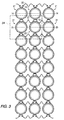
- Fig. 3 shows an 8x3 cell bundle array of fuel cells in the plenum of a generator, embodying the present invention.
- the array comprises rows of fuel cells, such as, for example, a first row 14 including fuel cells 17, 19, and 21, which are electrically connected in parallel by an electrically conducting member extending between cells.
- Fuel cells 17, 19, and 21 are also electrically connected in series with the fuel cells in the adjacent second row 25, including fuel cells 27, 29, and 31 by the member 22, as well as by strips of open cell nickel foam 51 (shown more clearly in Figs. 5 and 9) .
- Fig. 4 shows in more detail the group of fuel cells 34 using nickel foam strips 51 in accordance with this invention.
- the conducting member 22 is a thin sheet of porous, nickel such as an expanded or woven nickel mesh or screen which contacts the outer electrodes 32 of the cells 27 and 29 in the fuel cell row 25, and the open cell nickel foam 51 of the cells 17 and 19 in the upper row, with a single corrugation 52 with a top corrugated portion 53 of the conducting member between the fuel cells.
- the conducting member 22 also has bottom shoulder sections 42 connected to the top crowns 40 by corrugated crown sidewall 43, where the crowns and shoulder sections conform to the shape of their contacting tubular fuel cells, and each shoulder section 42 is connected to its adjacent shoulder section by conducting member 22.
- the sections connecting the crown and shoulder are not straight, but have a single corrugation 53 giving sufficient rigidity for the handling of the bundle during assembly of the generator while at the same time sufficient flexibility to the structure to accommodate any dimensional changes in the bundle structure which might be caused by differential thermal expansion of the bundle and ceramic structures which connect to the bundle.
- all of the outer interconnections 20 of the first row 14 of fuel cells, such as 17 and 19 face all of the outer electrodes of the second row 25 of fuel cells, such as 27 and 29. As shown, there are no metal felt connections between any fuel cells, but there is a complete substitution of an open pore nickel foam 51 which provides advantages of substantially lower cost relative to nickel felt and greater structural stability relative to nickel felt.
- Fig. 5 more clearly shows the character of the single corrugated 52 connector support of the conducting member, with corrugated sections 43 between crown and shoulder and a top corrugated portion 53.
- fuel cells are part of the rows of spaced apart, axially elongated tubular fuel cells (not shown here in any detail, for the sake of simplicity). All of the fuel cells comprise an inner self-supported air electrode 16, a solid electrolyte 18 (which is oxygen ion conductive at over 650°C), an outer fuel electrode 32 and an outer interconnection 20 as best shown in Fig. 4.
- the conducting member, with single corrugation 52 and top corrugated portion 53 consists of a strong expanded mesh, preferably of nickel, which is over about 60% porous, preferably 65% to 80% porous, having a thickness between 0.025 cm (0.01 inch) and 0.076 cm (0.03 inch), preferably from 0.012 cm (0.005 inch) to 0.076 cm (0.03inch). Material thickness which is substantially outside of the range of 0.012 cm through 0.076 cm becomes very difficult to corrugate to form crowns 40, crown corrugations 43 and shoulder portions 42. Under 0.012 cm, structural integrity suffers.
- the mesh is preferably at least 60 vol.% porous, so that fuel can pass easily outside the cells near the fuel electrodes 32, as well as to enable drying of a nickel particle-filled organic-based adhesive, not shown, which is used initially to bond the conducting member 22 to each row of the fuel cell, and the nickel foam 51 to the crown 40.
- the organic part of the adhesive preferably an epoxy resin filled with about 40 wt.% to 80 wt.% fine nickel particles, is burned off (or vaporized) during subsequent heating/sintering step at about 1000°C to 1200°C, prior to or after the fuel cell bundle is placed in the generator, that is, such sintering can occur at generator startup.
- Epoxy resin volatiles in particular, have been found to have no adverse effect on fuel cell properties.
- the conducting member 22 along with single corrugation 52 has a spring-like effect and provides superior shock absorbing qualities, as compared to metal felts. Additionally, the member 22 is not affected by prolonged operation of twelve months or more at temperatures up to 1200°C and the metal foam 51 will not shrink or slump (that is, densify and decrease in thickness), as will metal felts. This unique quality of the metal foam is an important feature of the invention, since the prevention of shrinkage of the bundle eliminates the present tendency of the cells to break fragile ceramic upper cell positioning boards.
- this invention is a means of providing the necessary series and parallel electrical connections between tubular solid oxide fuel cells when the cells are assembled in bundles.
- the means of connection are thin expanded nickel/foam assemblies. Strips of nickel foam are bonded to the crowns. These foam strips substantially improve the post sinter bonding between the connector and the cell interconnections.
- the entire connector unit is referred to as a "foam-top screen.”
- both series and parallel electrical connection of tubular solid oxide fuel cells within a bundle is accomplished by the use of the thin expanded nickel foam-top screens. In test assemblies the foam top screens have been 365 mm long. Four foam top screens are used at each junction to cover the length of the bundle.
- This invention embodies three important improvements relative to prior art. These are: (1) folds in the form of the screen that promotes flexibility in both series (eight cell) direction and parallel (three cell) direction. Flexibility connotes the ability of cells to move relative to other cells within the bundle without the application of substantial force.
- This attribute facilitates the engagement of ceramic structures that form fuel recirculation and exhaust plena at the open ends of the cells; (2) nickel foam tops which are bonded to the crowns of the screen and which substantially improve post sinter connector/interconnection bond strength and electrical conductivity; this improvement stems from a greatly increased number of points of connection to the interconnection plating that the use of a foam of fine reticulated structure provides; and (3) the inclusion of a ninth connector, which is reversed so that the foam tops connect to the fuel electrodes of an outer parallel connected group of three cells facilitates connections between bundle to adjacent bundle within a row of bundles, bundles to positive and negative power leads, and bundle row to bundle row.
- FIG. 7 bundle row to bundle row connections are shown where voids 70 between the top corrugated portion 53 of the single corrugation 52 of conducting members of the bottom row 72 of a top bundle 74 and the top row 76 of a bottom bundle 78 are filled with open cell nickel foam 51.
- Fig. 6 shows bundle to bundle connections where the top corrugated portion 53 of the single corrugation 52 of conducting members of the top row 80 of a top bundle 72' are connected to a top bundle to bundle current collector 82 having a top corrugated portion 53' to provide longitudinal voids 70' which are filled with open cell nickel foam 51.
- the top bundle to bundle current collector passes from top bundle 72' to an adjacent top bundle 72" over bundle separator insulation board 84.
- the top bundle to bundle current collector 82 is an inverted top screen.
- voids 70 and 70' in Figs. 6 and 7 between screen conducting members are filled with sandwiched open cell nickel foam 51 which provides improved electrical conductivity.
- the inclusion of foam strips 51 reduces the voltage drop from bundle to bundle to approximately 25% of the value which pertains if the foam strips are not included.
- bus bar 90 has an attached inverted screen conducting member 82' which as in the other cases shown in Fig. 6, inversely matches the top corrugated portion 53 to provide longitudinal voids 70' filled with open cell nickel foam 51.
- open cell nickel foam 51 will fill any longitudinal voids/openings 70, 70' between opposing top corrugated portions 53-53' as shown in Fig. 6, or 53-53' as shown in Fig. 7 or inset portions 88 into the bus bar 90.
- the inclusion of foam strips 51 reduces the voltage drop from bundle to bundle to approximately 25% of the value which pertains if the foam strips are not included.
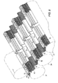
- Fig. 9 shows one type of idealized three dimensional representations of a useful nickel foam.
- a metallic foam is by impregnating an open cell flexible organic foam material, such as polyurethane, with an aqueous metallic slurry - containing fine metallic particles such as nickel particles. The impregnated organic foam is compressed to expel excess slurry. The material is then dried and fired to burn out the organic materials and to sinter the metal/ceramic coating. A rigid foam is thereby formed having a plurality of interconnecting voids having substantially the same structural configurations as the organic foam which was the starting material. The structure is generally seen in Fig.
- Fig. 10 generally shows in block form the method of this invention where a first and second row of fuel cells are provided 100, where outer interconnections of the first row face all the outer electrodes of a second row; where a flat sheet of expanded nickel mesh is provided 102, followed by forming 106 the heated mesh into a corrugated structure with a series of top crowns between shoulder sections with a single corrugation between those sections; where an adhesive is coated 108 to cover the crowns and a strip of open cell metal nickel foam is placed 110 on the adhesive covering the crown and then adding 112 more adhesive on top of the foam and upon the shoulders of the mesh and then placing 114 the mesh and foam structure between the fuel cell rows; and drying 116 the adhesive and sintering 118 the fuel cell assembly.
- Expanded nickel mesh having diamond-shaped openings, about 65% porous and 0.05 cm (0.02 inch) thick, was placed in a roller die mold which gave the mesh a corrugated structure with a crown contour approximated to fit the contour of tubular solid oxide fuel cells to be made into a bundle similar to that shown in Figs. 4 and 5.
- Each corrugated mesh structure was coated at the crown with a bead of epoxy cement admixed with about 70 wt.% small nickel particles.
- a thin strip of nickel foam (0.6 cm wide x 0.17 cm thick x 36 cm long), having a reticulated structure and about 85 pores per lineal inch, sold commercially by Inco under the model designation 200105031011 was placed on the bead of epoxy cement.
Landscapes
- Life Sciences & Earth Sciences (AREA)
- Engineering & Computer Science (AREA)
- Manufacturing & Machinery (AREA)
- Sustainable Development (AREA)
- Sustainable Energy (AREA)
- Chemical & Material Sciences (AREA)
- Chemical Kinetics & Catalysis (AREA)
- Electrochemistry (AREA)
- General Chemical & Material Sciences (AREA)
- Fuel Cell (AREA)
- Inert Electrodes (AREA)
Abstract
Description
Claims (10)
- A solid oxide fuel cell assembly (34) comprising rows of fuel cells, each having an outer interconnection (20) and an outer electrode (33), disposed next to each other with corrugated electrically conducting metal mesh between each row of cells, the corrugated mesh having a top crown portion (40) and a bottom shoulder portion (42), where a flexible open cell nickel foam (51) is disposed between and contacts both the crown portion and the outer interconnections of the fuel cells in a first row, and where the shoulder portion (42) of the mesh directly contacts the outer electrodes (32) of the fuel cells in a second row, said nickel foam and mesh electrically connecting each row of fuel cells, said mesh having a single corrugation (52) with a top portion between cells in a row and where there are no metal felt connections between any fuel cells.
- A plurality of solid oxide fuel cell assemblies (34) of Claim 1, comprising a fuel cell bundle, each bundle comprising:(1) a first row of spaced apart, axially elongated tubular fuel cells, each containing an outer electrode (32) and an outer interconnection (20);(2) a second row of space apart, axially elongated tubular fuel cells, each containing an outer electrode (32) and an outer interconnection (20), the second row being spaced apart from the first row, where all the outer interconnections of the first row fuel cells face all the outer electrodes of the second row fuel cells; and(3) an electrically conducting connector support for the fuel cells, extending between and contacting the first row and the second row of fuel cells, where the connector support consists of an expanded mesh more than about 60% porous and having a thickness between 0.012 cm and 0.076 cm, said connector support having a corrugated structure with a series of top crowns (40) connected to bottom shoulder sections (42), where the shoulder sections conform to the shape of their contacting tubular fuel cells, where each shoulder section (42) is connected to its adjacent shoulder section (42), where a flexible open cell nickel foam (51) is disposed between and contacts both of the top crowns and the interconnections of the first row fuel cells, and all of the support shoulder sections directly contact the outer electrodes of the second row fuel cells, said mesh having a single corrugation (52) with a top portion between fuel cells in a row and where there are no metal felt connections between any fuel cells.
- The solid oxide fuel assembly (34) of Claim 1, wherein the metal mesh is made of nickel.
- The solid oxide fuel assembly (34) of Claim 1, wherein the metal mesh is from 65% to 85% porous, and have a spring-like effect providing low force transmission property to the fuel cells.
- The solid oxide fuel assembly (34) of Claim 1, wherein the metal mesh is from 0.012 cm to 0.076 cm thick.
- The solid oxide fuel assembly (34) of Claim 1, wherein the nickel foam (51) has a reticulated structure and from about 75 pores to 105 pores per lineal inch, wherein the metal mesh and nickel foam (51) will not shrink or slump during prolonged operation at temperatures up to 1200°C.
- The fuel cell assemblies (34) of Claim 2, where each assembly comprises a fuel cell bundle including a bottom and top bundle, where, in the connection between each bundle, each bundle connector support contacts an adjacent bundle connector support, the single corrugation (52) in the adjacent mesh bundle connection as well as the top corrugated portions opposite each other form a void volume (70) which is filled with flexible open cell nickel foam, where the foam in the void volume (70) improves electrical connection from bundle to bundle.
- The solid oxide fuel assemblies (34) of Claim 7, wherein the nickel foam (51) has a reticulated structure and from about 75 pores to 105 pores per lineal inch.
- The solid oxide fuel assemblies (34) of Claim 7, wherein the connector support and attached nickel foam (51) will not shrink or slump during prolonged operation at temperatures of up to 1200°C.
- A method of manufacturing a solid oxide fuel cell assembly, comprising the steps of:(1) providing (100) a first and second row of spaced apart, axially elongated tubular fuel cells, the second row being spaced apart from the first row, each fuel cell containing an outer electrode and an outer interconnection, where all the outer interconnections of the first row fuel cells face all the outer electrodes of the second row fuel cells;(2) providing (102) a flat sheet of expanded nickel mesh having a porosity over about 60% and a thickness between 0.012 cm and 0.076 cm;(3) forming (106) the flat, expanded nickel mesh sheet into a corrugated structure with a series of top crowns connected to the bottom shoulder sections where the mesh between shoulder sections has a single corrugation with a top portion to provide a flexible connector support, and where at least the shoulder sections will conform to the shape of the tubular fuel cells of the first and second rows of fuel cells;(4) adding (108) an organic adhesive mixed with nickel powder to cover the crowns and shoulder portions of the corrugated nickel mesh connector support;(5) disposing (110) a strip of flexible open cell nickel foam on top of the adhesive covering the crown of the connector support;(6) adding (112) an organic adhesive mixed with nickel powder to the flexible open cell nickel foam strip;(7) disposing (114) the corrugated connector support with its top nickel foam with adhesive on both the top of the foam and both shoulders between the first and second rows of fuel cells, such that all of the nickel foam strips on the top of the connector support top crowns contact and adhere to the interconnections of the first row fuel cells and al of the connector support shoulder sections contact and adhere to the outer electrodes of the second row fuel cells;(8) drying (116) the adhesive by passing hot air through the porous connector support; and(9) sintering (118) the fuel cell assembly to vaporize the organic portion of the adhesive and provide an integral fuel cell assembly.
Applications Claiming Priority (2)
| Application Number | Priority Date | Filing Date | Title |
|---|---|---|---|
| US444623 | 1999-11-22 | ||
| US10/444,623 US7157172B2 (en) | 2003-05-23 | 2003-05-23 | Combination nickel foam expanded nickel screen electrical connection supports for solid oxide fuel cells |
Publications (3)
| Publication Number | Publication Date |
|---|---|
| EP1531513A2 true EP1531513A2 (en) | 2005-05-18 |
| EP1531513A3 EP1531513A3 (en) | 2005-05-25 |
| EP1531513B1 EP1531513B1 (en) | 2007-01-03 |
Family
ID=33450702
Family Applications (1)
| Application Number | Title | Priority Date | Filing Date |
|---|---|---|---|
| EP04011641A Expired - Lifetime EP1531513B1 (en) | 2003-05-23 | 2004-05-17 | Combination nickel foam expanded nickel screen electrical connection supports for solid oxide fuel cells |
Country Status (5)
| Country | Link |
|---|---|
| US (1) | US7157172B2 (en) |
| EP (1) | EP1531513B1 (en) |
| JP (1) | JP4815106B2 (en) |
| CA (1) | CA2468198A1 (en) |
| DE (1) | DE602004004037T2 (en) |
Cited By (2)
| Publication number | Priority date | Publication date | Assignee | Title |
|---|---|---|---|---|
| WO2008119328A1 (en) * | 2007-04-02 | 2008-10-09 | Staxera Gmbh | Interconnector arrangement and method for producing a contact arrangement for a fuel cell stack |
| EP4273971A4 (en) * | 2020-12-30 | 2025-08-06 | Topaz Llc Topaz Llc | Tubular solid oxide fuel cell with cathode collector and method for producing the same |
Families Citing this family (30)
| Publication number | Priority date | Publication date | Assignee | Title |
|---|---|---|---|---|
| US8048587B2 (en) * | 2002-11-27 | 2011-11-01 | Delphi Technologies, Inc. | Compliant current collector for fuel cell anode and cathode |
| JP4623994B2 (en) * | 2003-12-05 | 2011-02-02 | 京セラ株式会社 | Fuel cell |
| US7364812B2 (en) * | 2004-03-19 | 2008-04-29 | Pittsburgh Electric Engines, Inc. | Multi-function solid oxide fuel cell bundle and method of making the same |
| US20050037252A1 (en) * | 2004-08-06 | 2005-02-17 | Pham Ai Quoc | Tubular solid oxide fuel cells |
| JP3965502B2 (en) * | 2004-10-27 | 2007-08-29 | Toto株式会社 | Conductive member for solid oxide fuel cell stack |
| US8628891B2 (en) * | 2005-12-15 | 2014-01-14 | Acumentrics Corporation | Interconnection of bundled solid oxide fuel cells |
| US8062798B2 (en) * | 2006-11-06 | 2011-11-22 | Siemens Energy, Inc. | Solid oxide fuel cell generator with mid-stack fuel feed |
| US20090050680A1 (en) * | 2007-08-24 | 2009-02-26 | Protonex Technology Corporation | Method for connecting tubular solid oxide fuel cells and interconnects for same |
| US8097381B2 (en) | 2007-09-21 | 2012-01-17 | Siemens Energy, Inc. | Solid oxide fuel cell generator including a glass sealant |
| US8673519B2 (en) | 2007-09-28 | 2014-03-18 | Siemens Aktiengesellschaft | Aid for electrical contacting of high-temperature fuel cells and method for production thereof |
| US8043752B2 (en) * | 2008-05-06 | 2011-10-25 | Siemens Energy, Inc. | Fuel cell generator with fuel electrodes that control on-cell fuel reformation |
| JP5192301B2 (en) * | 2008-06-30 | 2013-05-08 | 株式会社日立製作所 | Solid oxide fuel cell and method for producing the same |
| US8097384B2 (en) * | 2008-07-08 | 2012-01-17 | Siemens Energy, Inc. | Solid oxide fuel cell with transitioned cross-section for improved anode gas management at the open end |
| DE102008049564A1 (en) * | 2008-09-30 | 2010-04-01 | Siemens Aktiengesellschaft | Method for producing a tubular solid electrolyte fuel cell (SOFC) and associated tubular fuel cell |
| WO2011006668A1 (en) * | 2009-07-16 | 2011-01-20 | Ezelleron Gmbh | Fuel cell stack |
| KR101109222B1 (en) * | 2009-08-05 | 2012-01-30 | 삼성전기주식회사 | Fuel Cell Stack with Integral Support |
| US8163433B2 (en) * | 2009-08-19 | 2012-04-24 | Siemens Energy, Inc. | Fuel cell integral bundle assembly including ceramic open end seal and vertical and horizontal thermal expansion control |
| US8460838B2 (en) * | 2009-08-19 | 2013-06-11 | Siemens Energy, Inc. | Generator module architecture for a large solid oxide fuel cell power plant |
| KR20110030878A (en) * | 2009-09-18 | 2011-03-24 | 삼성에스디아이 주식회사 | Unit cell and stack of solid oxide fuel cell |
| ES2363294B1 (en) * | 2009-10-09 | 2012-06-04 | Ikerlan,S. Coop | SOLID OXIDE FUEL BATTERY |
| JP5483259B2 (en) * | 2010-03-30 | 2014-05-07 | Toto株式会社 | Fuel cell assembly |
| KR101278316B1 (en) * | 2011-11-30 | 2013-06-25 | 삼성전기주식회사 | Solid Oxide Fuel Cell |
| KR101278419B1 (en) * | 2011-12-01 | 2013-06-24 | 삼성전기주식회사 | Solid oxide fuel cell stack and producing method thereof |
| KR101301396B1 (en) * | 2011-12-22 | 2013-08-28 | 삼성전기주식회사 | Solid oxide fuel cell and current collecting method thereof |
| KR102033904B1 (en) * | 2012-09-12 | 2019-10-21 | 주식회사 미코 | Interconnector for tubular fuel cells and structure including the same |
| KR20140053568A (en) * | 2012-10-26 | 2014-05-08 | 삼성전기주식회사 | Solid oxide fuel cell module |
| EP2973829B1 (en) * | 2013-03-15 | 2022-05-04 | Watt Fuel Cell Corp. | Solid oxide fuel cell bundles with flexible power transmission system |
| KR101528075B1 (en) * | 2013-12-24 | 2015-06-10 | 주식회사 포스코 | Cathode current collector for solid oxide fuel cell |
| DE102014214755A1 (en) * | 2014-07-28 | 2016-01-28 | Robert Bosch Gmbh | Fuel cell system with improved contacting |
| GB202101737D0 (en) * | 2021-02-09 | 2021-03-24 | Rolls Royce Plc | Electrical power system bus bars |
Family Cites Families (15)
| Publication number | Priority date | Publication date | Assignee | Title |
|---|---|---|---|---|
| US4490444A (en) | 1980-12-22 | 1984-12-25 | Westinghouse Electric Corp. | High temperature solid electrolyte fuel cell configurations and interconnections |
| JPS6093768A (en) | 1983-10-28 | 1985-05-25 | Toshiba Corp | Fuel cell power generating system |
| US4648945A (en) | 1985-03-21 | 1987-03-10 | Westinghouse Electric Corp. | Bipolar plating of metal contacts onto oxide interconnection for solid oxide electrochemical cell |
| US4833045A (en) | 1987-12-10 | 1989-05-23 | Westinghouse Electric Corp. | Porous electronic current collector bodies for electrochemical cell configurations |
| US5258240A (en) | 1991-10-11 | 1993-11-02 | Westinghouse Electric Corp. | Solid oxide fuel cell generator |
| US5273838A (en) | 1992-10-07 | 1993-12-28 | Westinghouse Electric Corp. | Double interconnection fuel cell array |
| US5456833A (en) | 1994-05-02 | 1995-10-10 | Selee Corporation | Ceramic foam filter having a protective sleeve |
| JP3280819B2 (en) | 1995-02-28 | 2002-05-13 | 三洋電機株式会社 | Internal reforming molten carbonate fuel cell |
| JP3447541B2 (en) * | 1997-12-25 | 2003-09-16 | 京セラ株式会社 | Cylindrical solid oxide fuel cell and fuel cell |
| AUPQ315499A0 (en) * | 1999-09-29 | 1999-10-21 | Ceramic Fuel Cells Limited | Fuel cell assembly |
| JP4562230B2 (en) * | 2000-02-29 | 2010-10-13 | 京セラ株式会社 | Manufacturing method of solid electrolyte fuel cell |
| US6379831B1 (en) | 2000-08-02 | 2002-04-30 | Siemens Westinghouse Power Corporation | Expanded nickel screen electrical connection supports for solid oxide fuel cells |
| US6416897B1 (en) | 2000-09-01 | 2002-07-09 | Siemens Westinghouse Power Corporation | Tubular screen electrical connection support for solid oxide fuel cells |
| JP4683742B2 (en) * | 2001-02-27 | 2011-05-18 | 京セラ株式会社 | Fuel cell |
| JP4399698B2 (en) * | 2001-03-30 | 2010-01-20 | 三菱マテリアル株式会社 | Air electrode current collector and solid electrolyte fuel cell incorporating the air electrode current collector |
-
2003
- 2003-05-23 US US10/444,623 patent/US7157172B2/en not_active Expired - Fee Related
-
2004
- 2004-05-17 EP EP04011641A patent/EP1531513B1/en not_active Expired - Lifetime
- 2004-05-17 DE DE602004004037T patent/DE602004004037T2/en not_active Expired - Lifetime
- 2004-05-21 CA CA002468198A patent/CA2468198A1/en not_active Abandoned
- 2004-05-24 JP JP2004152706A patent/JP4815106B2/en not_active Expired - Fee Related
Cited By (4)
| Publication number | Priority date | Publication date | Assignee | Title |
|---|---|---|---|---|
| WO2008119328A1 (en) * | 2007-04-02 | 2008-10-09 | Staxera Gmbh | Interconnector arrangement and method for producing a contact arrangement for a fuel cell stack |
| DE102007016905A1 (en) * | 2007-04-02 | 2008-10-09 | Staxera Gmbh | Interconnector arrangement and method for producing a contact arrangement for a fuel cell stack |
| EP1981108A1 (en) * | 2007-04-02 | 2008-10-15 | Staxera GmbH | Interconnector assembly and method for manufacturing a connector assembly for a fuel cell stack |
| EP4273971A4 (en) * | 2020-12-30 | 2025-08-06 | Topaz Llc Topaz Llc | Tubular solid oxide fuel cell with cathode collector and method for producing the same |
Also Published As
| Publication number | Publication date |
|---|---|
| US7157172B2 (en) | 2007-01-02 |
| DE602004004037T2 (en) | 2007-05-31 |
| DE602004004037D1 (en) | 2007-02-15 |
| EP1531513A3 (en) | 2005-05-25 |
| US20040234830A1 (en) | 2004-11-25 |
| JP4815106B2 (en) | 2011-11-16 |
| EP1531513B1 (en) | 2007-01-03 |
| JP2004349262A (en) | 2004-12-09 |
| CA2468198A1 (en) | 2004-11-23 |
Similar Documents
| Publication | Publication Date | Title |
|---|---|---|
| EP1531513B1 (en) | Combination nickel foam expanded nickel screen electrical connection supports for solid oxide fuel cells | |
| US6379831B1 (en) | Expanded nickel screen electrical connection supports for solid oxide fuel cells | |
| US6416897B1 (en) | Tubular screen electrical connection support for solid oxide fuel cells | |
| US5171646A (en) | Fuel cell system including porous, panel type support and process for producing the same | |
| JP2947557B2 (en) | High temperature solid electrolyte fuel cell power generator | |
| US5270131A (en) | Module for a fuel cell battery | |
| US4913982A (en) | Fabrication of a monolithic solid oxide fuel cell | |
| US6589681B1 (en) | Series/parallel connection of planar fuel cell stacks | |
| US5882809A (en) | Solid oxide fuel cell with multi-unit construction and prismatic design | |
| US4791035A (en) | Cell and current collector felt arrangement for solid oxide electrochemical cell combinations | |
| US5258240A (en) | Solid oxide fuel cell generator | |
| JP2002502100A (en) | Solid oxide fuel cell connector | |
| CA2906879A1 (en) | Solid oxide fuel cell bundles with flexible power transmission system | |
| US8323845B2 (en) | Solid oxide electrolyte fuel cell plate structure, stack and electrical power generation unit | |
| CA2633322A1 (en) | Interconnection of bundled solid oxide fuel cells | |
| AU647344B2 (en) | Apparatus and method of fabricating a monolithic solid oxide fuel cell | |
| CA2427501A1 (en) | Solid oxide fuel cell stack | |
| EP0536909B1 (en) | Solid oxide fuel cell generator | |
| US20120088178A1 (en) | Fuel cell and manufacturing method thereof | |
| JP5105930B2 (en) | Solid oxide fuel cell module | |
| JPH05275096A (en) | Close board for solid electrolytic fuel cell, and solid electrolytic fuel cell using same and manufacture thereof | |
| JPH1125999A (en) | Solid oxide fuel cell | |
| JP6773470B2 (en) | Electrochemical reaction unit and electrochemical reaction cell stack | |
| JP2007328939A (en) | Tube type solid electrolyte fuel cell | |
| JP2769629B2 (en) | Cylindrical solid electrolyte fuel cell |
Legal Events
| Date | Code | Title | Description |
|---|---|---|---|
| PUAI | Public reference made under article 153(3) epc to a published international application that has entered the european phase |
Free format text: ORIGINAL CODE: 0009012 |
|
| PUAL | Search report despatched |
Free format text: ORIGINAL CODE: 0009013 |
|
| AK | Designated contracting states |
Kind code of ref document: A2 Designated state(s): AT BE BG CH CY CZ DE DK EE ES FI FR GB GR HU IE IT LI LU MC NL PL PT RO SE SI SK TR |
|
| AX | Request for extension of the european patent |
Extension state: AL HR LT LV MK |
|
| AK | Designated contracting states |
Kind code of ref document: A3 Designated state(s): AT BE BG CH CY CZ DE DK EE ES FI FR GB GR HU IE IT LI LU MC NL PL PT RO SE SI SK TR |
|
| AX | Request for extension of the european patent |
Extension state: AL HR LT LV MK |
|
| 17P | Request for examination filed |
Effective date: 20050506 |
|
| RAP1 | Party data changed (applicant data changed or rights of an application transferred) |
Owner name: SIEMENS POWER GENERATION, INC. |
|
| AKX | Designation fees paid |
Designated state(s): DE FR GB IT |
|
| GRAP | Despatch of communication of intention to grant a patent |
Free format text: ORIGINAL CODE: EPIDOSNIGR1 |
|
| GRAS | Grant fee paid |
Free format text: ORIGINAL CODE: EPIDOSNIGR3 |
|
| GRAA | (expected) grant |
Free format text: ORIGINAL CODE: 0009210 |
|
| AK | Designated contracting states |
Kind code of ref document: B1 Designated state(s): DE FR GB IT |
|
| REG | Reference to a national code |
Ref country code: GB Ref legal event code: FG4D |
|
| REF | Corresponds to: |
Ref document number: 602004004037 Country of ref document: DE Date of ref document: 20070215 Kind code of ref document: P |
|
| ET | Fr: translation filed | ||
| PLBE | No opposition filed within time limit |
Free format text: ORIGINAL CODE: 0009261 |
|
| STAA | Information on the status of an ep patent application or granted ep patent |
Free format text: STATUS: NO OPPOSITION FILED WITHIN TIME LIMIT |
|
| 26N | No opposition filed |
Effective date: 20071005 |
|
| REG | Reference to a national code |
Ref country code: DE Ref legal event code: R081 Ref document number: 602004004037 Country of ref document: DE Owner name: SIEMENS ENERGY, INC.(N.D. GES.D. STAATES DELAW, US Free format text: FORMER OWNER: SIEMENS POWER GENERATION, INC., ORLANDO, US Effective date: 20110516 |
|
| REG | Reference to a national code |
Ref country code: FR Ref legal event code: CD Owner name: SIEMENS ENERGY, INC. Effective date: 20120413 |
|
| PGFP | Annual fee paid to national office [announced via postgrant information from national office to epo] |
Ref country code: DE Payment date: 20120720 Year of fee payment: 9 |
|
| PGFP | Annual fee paid to national office [announced via postgrant information from national office to epo] |
Ref country code: GB Payment date: 20130516 Year of fee payment: 10 |
|
| PGFP | Annual fee paid to national office [announced via postgrant information from national office to epo] |
Ref country code: FR Payment date: 20130618 Year of fee payment: 10 Ref country code: IT Payment date: 20130528 Year of fee payment: 10 |
|
| PG25 | Lapsed in a contracting state [announced via postgrant information from national office to epo] |
Ref country code: DE Free format text: LAPSE BECAUSE OF NON-PAYMENT OF DUE FEES Effective date: 20131203 |
|
| REG | Reference to a national code |
Ref country code: DE Ref legal event code: R119 Ref document number: 602004004037 Country of ref document: DE Effective date: 20131203 |
|
| GBPC | Gb: european patent ceased through non-payment of renewal fee |
Effective date: 20140517 |
|
| REG | Reference to a national code |
Ref country code: FR Ref legal event code: ST Effective date: 20150130 |
|
| PG25 | Lapsed in a contracting state [announced via postgrant information from national office to epo] |
Ref country code: IT Free format text: LAPSE BECAUSE OF NON-PAYMENT OF DUE FEES Effective date: 20140517 |
|
| PG25 | Lapsed in a contracting state [announced via postgrant information from national office to epo] |
Ref country code: GB Free format text: LAPSE BECAUSE OF NON-PAYMENT OF DUE FEES Effective date: 20140517 Ref country code: FR Free format text: LAPSE BECAUSE OF NON-PAYMENT OF DUE FEES Effective date: 20140602 |